
Abstract
Considering the insufficiency of numerical study on the percussion characteristic of hydraulic rock drill, which restricts the improvement of efficiency and reliability, a coupling model including the impact piston, spool valve, impact accumulator, and connecting pipelines was established taking into account the oil compressibility, oil leakage, and pressure drop in valve ports. The rebound velocity of impact piston was calculated based on the stress wave theory. The simulation results revealed the coupling mechanism of percussion system. Pressure curves of the piston’s front-chamber and rear-chamber, and valve’s left-chamber and right-chamber were obtained by field rock drilling test. Then, the velocity curve of impact piston was obtained after judging the striking point through the feature of rear-chamber’s pressure spike, so were the rock drill’s impact energy, impact frequency, and impact power. The simulation and experimental results have consistency. And, on this basis, the influence of spool valve’s damping clearance (δ) and pipeline diameters (d1, d2) connecting the impact piston and spool valve on the percussion performance and system cavitation was researched. The results show that the larger δ is better considering reversal time of spool valve, the impact frequency of rock drill, pressure fluctuation, and cavitation relief. But too large δ will cause over quick impact velocity of the spool valve, which may lead to strong vibration and the damage of spool valve. The optimal value of δ is 0.01 mm by comprehensive consideration. The pipeline diameters have an important influence on the pressure fluctuation and negative pressure in rear-chamber. The diameters should be larger than 18 mm to alleviate the cavitation. This article provides means for the design and research of rock drills.
Keywords
Introduction
In recent years, hydraulic rock drills have been widely used in many applications, such as mining, coal mine roadway excavation, railway tunnel, highway tunnel, and rock excavation projects because of their high efficiency, clean, and safety.1,2 The hydraulic rock drill with high frequency and high power becomes the first choice facing the scale of mining and larger-scale tunneling.3,4 Different from the DTH (down-the-hole) hammers,5–7 the hydraulic rock drill is driven by hydraulic system and belongs to top hammer drilling. As the core component of rock drill, the performance of percussion system decides the whole level of rock drill to a great extent.8,9 However, the structure of percussion system is complicated, and its working process obeys the hydraulic–mechanical–pneumatic coupling laws, 10 which introduces great difficulty in researching on the percussion characteristic of hydraulic rock drill.
J Seo and colleagues11–13 developed an analysis model for rock drill using SimulationX software, which was validated by the static calibration and measurement tests of impact frequency and impact energy under three different supply pressure conditions. Based on a simulation model for rock drill built by AMESim, JY Oh et al. 14 studied the dynamic performance of percussion system and effects of rock hardness on it. JY Oh et al. 15 also investigated the influence of percussion system parameters on percussion performance and found that the impact power was affected by supply pressure, areas of the impact piston and shuttle valve, and position of the hydraulic port strongly. Q Hu et al. 16 studied the percussion performance of rock drill with single-degree-of-freedom impact oscillator model and revealed that the simulation results were consistent with stress wave test results. S Yang and colleagues17–19 analyzed the percussion performance of rock drill and optimized the parameters with simulation model, which was validated by the percussion performance test. C Song et al. 20 optimized the design parameters of percussion system for rock drill using Taguchi method. Y Li et al., 21 J Hu and Q Hu, 22 and H Zhao et al. 23 analyzed the influence of the opening at zero position of distribute valve on the internal motion law for the hydraulic rock drill. W Ding and X Huang 24 established a hydraulic impactor simulation system based on the theory of bond graph in AMESim software. Z Zhou et al. 25 and Z Yin and Y Hu 26 studied the dynamic characteristics of a percussion system using AMESim and obtained motion law of the impact piston and spool valve. Z Wen et al. 27 built a simulation model for a percussion system and studied the effects of some factors on the percussion performance.
The previous research works on percussion system are mostly the simulation analysis, and the simulation models are too simplified. The simulation results are quite different from the actual condition. There are many problems including cavitation erosion of impact piston and bush, impact powerless of the rock drill, and so on, which cannot be researched by simulation. For this reason, a coupling model including impact piston, spool valve, impact accumulator, and connecting pipelines will be established considering the oil compressibility, oil leakage, and pressure drop in valve ports. The rebound velocity of impact piston will be calculated based on the stress wave theory. The field rock drilling test will be conducted to verify the numerical model by contrasting the change law of pressure and percussion performance by simulation and experiment. Above all, the influencing factors on the percussion characteristic of rock drill will be researched.
Working principle of hydraulic rock drill
Figure 1 shows the schematic diagram of percussive drilling. Under the action of percussion system, the impact piston hits the shank adapter with high frequency and high speed. Its kinetic energy is transmitted to rock through shank adapter, drill rod, and drill bit in the form of stress wave. The impact piston will rebound under the reflected wave because of the difference in wave resistance.
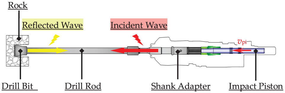
Schematic diagram of the percussive drilling.
As shown in Figure 2, the percussion system with no constant-pressurized chamber is mainly composed of an impact piston, a spool valve, an impact accumulator, a regulating plug, and a body. The impact piston connects the spool valve with pipeline 1 and pipeline 2. Their movement obeys the principle of hydraulic slave. The pressure in front-chamber and rear-chamber exchanges under a certain frequency. The frequency of rock drill can be adjusted through the regulating plug.

Schematic diagram of the percussion system.
Coupling model of percussion system
Stress wave model
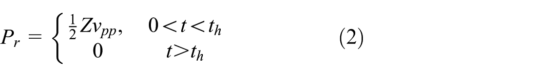
The solving equation of incident wave is as follows 28

where Pr is the incident stress wave (Pa); Zh and Zq are the wave resistance (N s m−1) of impact piston and shank adapter, respectively; vpp is the last impact velocity of impact piston (m s−1); and th is the duration of incident wave (s).
The wave resistance of the impact piston and shank adapter are equal, namely, Zh = Zq = Z. So
Among them

where Lh is the length of impact piston (m); c is the wave velocity (m s−1); A, E, and ρ are the cross sectional area (m2), elastic modulus (Pa), and density (kg m−3) of impact piston, respectively.
Extensive experiments4,29,30 illustrate that near-linear relationship exists between the penetration force and penetration depth. So, equation (4) is satisfied
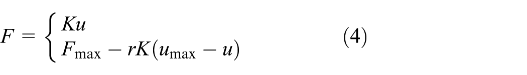
where K is the load stiffness of rock (N m−1); u was the penetration depth (m); and γ is the unload coefficient.
The wave superposition equation (5) is as follows regarding the interface surface between drill bit and rock as the research object

where Qr is the reflected wave.
Equations (6) and (7) are dynamic equations for loading and unloading section, respectively, which are obtained by uniting equations (2), (4), and (5)


Then, function of reflected wave is obtained

The rebound velocity of impact piston

Among them
Mathematical model of impact piston
As shown in Figure 3, Cv1 and Cv2 are the front-chamber and rear-chamber of impact piston, respectively. Considering viscous friction and friction force of seal, the dynamic model (equation (11)) of impact piston can be established according to Newton’s mechanics

Among them

where mp is the mass of impact piston (kg); Kp is the viscous friction coefficient (kg s−1); Ff is the friction force of the seal (N);

Structure diagram of the impact piston part.
The liquid flow continuity equation of front-chamber (equation (13)) and rear-chamber (equation (14)) are established
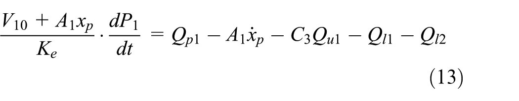
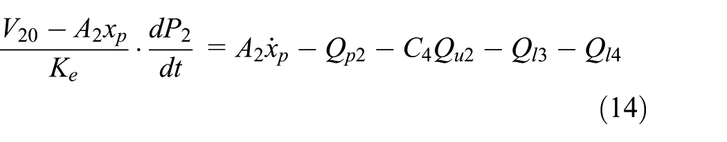

where Vi0 is the initial volume (m3) of Cvi (i = 1, 2); Ke is the oil elastic modulus (MPa); C3 and C4 are variables for state judgment (0 or 1); and Pi is the pressure (Pa) corresponding to Cvi (i = 1, 2). Other parameters are shown in Figure 3.
Mathematical model of spool valve
Considering the viscous friction and pressure in each chamber, the dynamic model (equation (16)) of spool valve can be established referring to Figure 4

Among them
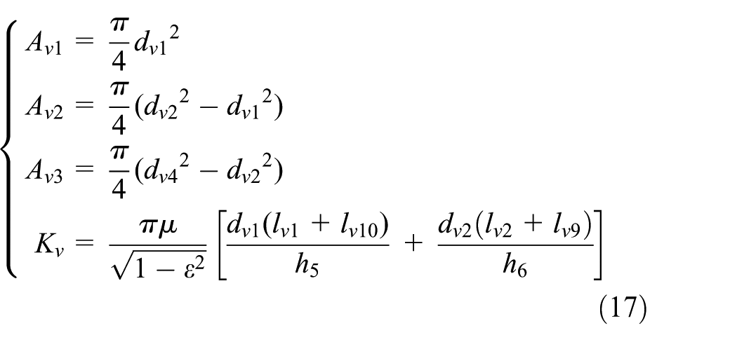
where mv is the mass of spool valve (kg); Kv is the viscous friction coefficient (kg s−1); xv and xv are the velocity (m s−1) and acceleration (m s−2) of spool valve, respectively; Pi is the pressure (Pa) corresponding to Cvi (i = 3, 4, 5, 6); Avi (i = 1, 2, 3) is the effective area of spool valve (m2); and h5 and h6 is the fit clearance (m) corresponding to dv1 and dv2. Other parameters are shown in Figure 4.

Structure diagram of the spool valve part.
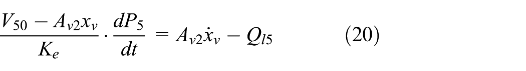
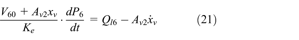
The liquid flow continuity equation of valve’s left-chamber (equation (18)), right-chamber (equation (19)), Cv5 (equation (20)), and Cv6 (equation (21)) are established.


Among them

where Vi0 is the initial volume of Cvi (i = 3, 4, 5, 6) (m3). Other parameters are shown in Figures 3 and 4.
Mathematical model of impact accumulator
It is close to an isentropic process in the air chamber of impact accumulator while drilling. So, equation (23) is satisfied

Among them

where Ph is the pressure in oil chamber (Pa); VH is the gas volume (m3); VH0 is the initial gas volume (m3); and Qh is the flow rate into accumulator (m3 s−1).
Mathematical model of pipelines
The equilibrium equation and liquid flow continuity equation of pipeline 1 and pipeline 2 (Figure 2) were established considering the capacity, resistance, and inertia

Among them
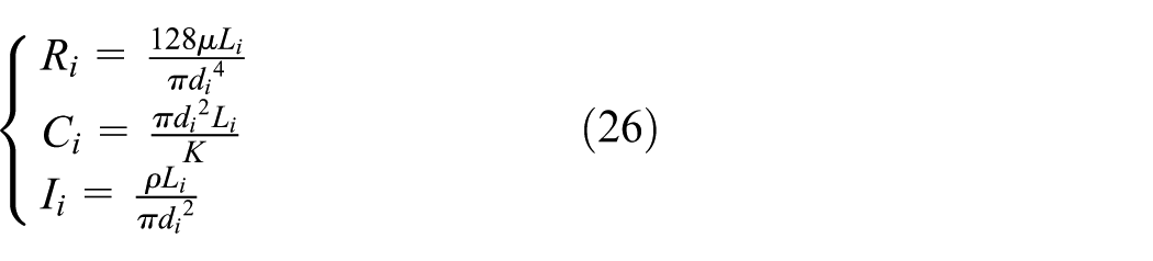
where Ri, Ci, and Ii (i = 1, 2) are the liquid resistance, liquid capacity, and hydraulic inductance of pipelines, respectively. Li and di (i = 1, 2) are the length and diameter of pipelines, respectively.
Numerical simulation and experimental validation
Numerical simulation of percussion system
Table 1 shows the initial parameters of percussion system. The percussion characteristic is simulated by solving the coupling model with MATLAB software. The simulation results are shown in Figure 5.
Initial parameters of the percussion system.

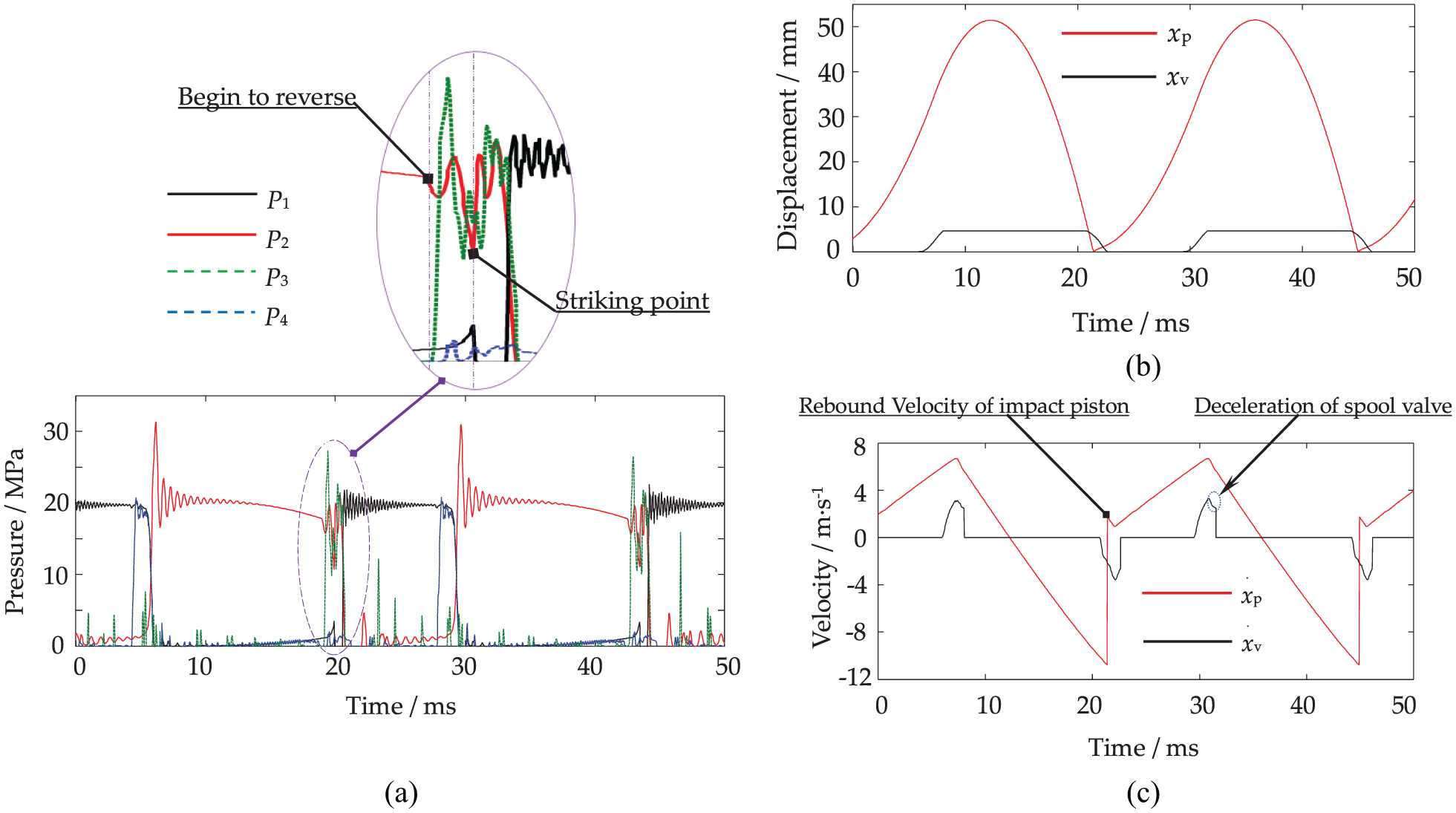
Simulation results of the percussion system: (a) pressure curves of impact piston’s front-chamber and rear-chamber, valve’s left-chamber and right-chamber; (b) displacement curves of the impact piston and spool valve; and (c) velocity curves of the impact piston and spool valve.
From Figure 5, we can observe the following:
The high pressure alternately appears in the front-chamber and rear-chamber, namely, no constant-pressurized chamber.
There exists pressure fluctuation in chambers because of high-frequency and high-velocity reciprocating motion of the impact piston and spool valve, and the peak pressure of rear-chamber can reach 30 MPa during the braking phase of impact piston. The pressure of rear-chamber will drop sharply when hydraulic oil comes into left-chamber of the valve and then a pressure spike appears because of impact piston’s rebound.
The reversal time of spool valve is about 2 ms, and there exists deceleration before destination.
Field rock drilling test
As shown in Figure 6, the rock drill was mounted in a drill rig. Pressure sensors were installed on the housing. The pressure in the impact piston’s front-chamber and rear-chamber, and valve’s left-chamber and right-chamber was tested synchronously. The sampling frequency could reach 204.8 kHz with 40 opening channels using the LMS SCADAS Mobile. The software for signal acquisition was the LMS Test Xpress 7A. Pressure sensors were the Titanium Electronic Equipment Company’s PPM-S114A type, whose response frequency was 100 kHz. Pressure signals were transmitted to the test system via shielded wire and BNC plug.

Scene graph of the field rock drilling test.
Simulation model validation using experimental results
Pressure curves
The comparison of pressure curves by experiment and simulation is shown in Figure 7. We can observe that they have consistency in frequency, amplitude, and change law. The wave frequencies of P1 and P2 were different due to the spatial structure of the chambers, so was the return oil pressure of P2.

Correlation curves by experiment and simulation: (a) pressure curves of impact piston’s front-chamber and rear-chamber; (b) pressure curves of valve’s left-chamber and right-chamber.
Percussive performance
The kinetic equation (27) of impact piston is established. The striking point can be judged through the feature of rear-chamber’s pressure spike because of impact piston’s rebound. Then, the velocity curve of impact piston can be obtained by feeding pressure data of front-chamber and rear-chamber into equations (11), (12), and (27), which is shown in Figure 8. After that, the impact velocity can be obtained and so are the impact energy, impact frequency, and impact power


Testing curve of the pressure in chambers and velocity curve of the impact piston calculated with experimental data.
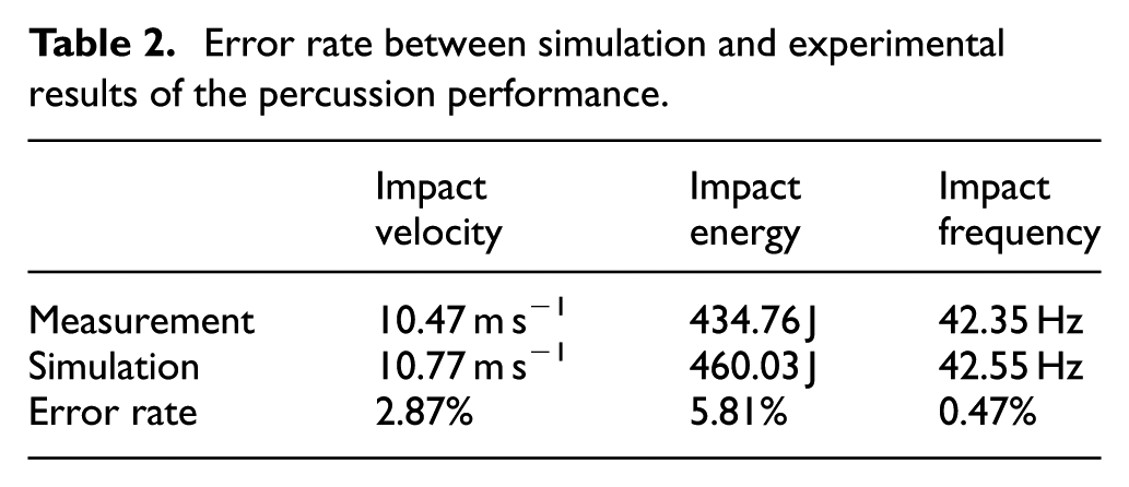
Table 2 contains relative deviations between experimental and simulation results. The impact velocity of piston by simulation was higher due to the difference of return oil pressure by experiment and simulation. But the error rates are all less than 10% and even the error rate of impact frequency is 0.47%, which verifies the rationality and correctness of the simulation model.
Error rate between simulation and experimental results of the percussion performance.
Analysis on factors influencing percussion characteristic
Y Li et al. 31 found that the damping clearance of the spool valve (δ) is closely related to the percussion performance, but they do not reveal the rule by simulation. G Yang and colleagues32,33 found the cavitation erosion phenomena of the impact piston and bush (Figure 9) in long-term use of rock drills, while they failed to find out the problem nature. The pressure and flow in the percussion system change greatly. The cavitation characteristics of system will be affected by the response of impact piston, which is related to the diameter of pipeline 1 and pipeline 2 (Figure 2). Therefore, the simulation will be carried out with different δ and pipe diameters considering the capacity, resistance, and inertia.

Cavitation erosion of the impact piston and bush.
Damping clearance of spool valve
The velocity curve of impact piston and spool valve, and the pressure curve of front-chamber and rear-chamber are obtained by simulation with different damping clearances of spool valve δ, which is shown in Figure 10, and we can observe the following:
The damping clearance of spool valve (δ) has an important influence on the impact velocity and reversal time of spool valve. When δ is 0.08, 0.10 and 0.12 mm, the impact velocity of spool valve is 1.499, 2.475, and 3.915 m s−1, and the reversal time of spool valve is 2.8, 2.1 and 1.8 ms.
The motion period of impact piston is affected because of variation of the spool valve’s motion. When δ is 0.08, 0.10, and 0.12 mm, the motion period was 24.1, 23.5 and 23 ms, and the corresponding impact frequency of rock drill is 41.49, 42.55, and 43.48 Hz.
During the braking phase of impact piston, the pressure fluctuation of rear-chamber (P2) will become severe when δ is 0.08 mm, and the peak pressure can reach 40 MPa. Besides, the negative pressure (–0.09 MPa) of front-chamber (P1) will last 0.8 ms, which is longer than that when δ is 0.10 and 0.12 mm. This will aggravate the cavitation of percussion system.

Simulation results of the percussion system with different δ values: (a) velocity curves of the impact piston and spool valve; (b) pressure curves of impact piston’s front-chamber and rear-chamber.
It can be concluded that the larger δ is better considering reversal time of spool valve, the impact frequency of rock drill, pressure fluctuation, and cavitation relief. But too large δ will cause over quick impact velocity of the spool valve, which may lead to strong vibration and the damage of spool valve. Based on the above analysis, the damping clearance of spool valve δ should be 0.01 mm by comprehensive consideration.
Connecting pipeline diameter
The simulation is carried out with different diameters of pipeline 1 and pipeline 2 (Figure 2) considering the capacity, resistance, and inertia. The results are shown in Figure 11, and we can observe the following:
The impact frequency of rock drill has little difference.
During the braking phase of impact piston, the pressure fluctuation in rear-chamber will become very severe when pipeline diameter is 17 mm. In contrast, the pressure fluctuation is stationary when pipeline diameter values are 18 and 19 mm.
When pipeline diameter is 17 mm, the negative pressure (–0.09 MPa) in rear-chamber will appear continuously during the return acceleration phase of impact piston, which will aggravate the cavitation of percussion system.

Simulation results of the percussion system with different diameters of connecting pipeline.
It can be found that the pipeline diameter should be larger than 18 mm considering the pressure fluctuation and cavitation relief.
Conclusion
The calculation formula of impact piston’s rebound velocity was derived. The coupling model including impact piston, spool valve, impact accumulator, and connecting pipelines was established considering the structural feature and dynamic characteristics of the percussion system.
The pressure curves of impact piston’s front-chamber and rear-chamber, valve’s left-chamber and right-chamber were obtained by the field rock drilling test. The velocity curve of impact piston was acquired. The simulation and experimental results had consistency. The simulation model was verified.
The influence of damping clearance (δ) on the percussion performance was researched. The results show that the larger one is better considering reversal time of spool valve, the impact frequency of rock drill, pressure fluctuation, and cavitation relief. But too large one would cause over quick impact velocity of the spool valve, which may lead to strong vibration and the damage of spool valve. Based on the above analysis, the damping clearance of spool valve (δ) should be 0.01 mm by comprehensive consideration.
The cavitation erosion of the impact piston and bush is closely related to the damping clearance (δ) and pipeline diameters (δ). The negative pressure (–0.09 MPa) of front-chamber (P1) will last 0.8 ms when δ is 0.08 mm. It is longer than that when δ is 0.10 and 0.12 mm. This will aggravate the cavitation of percussion system. Besides, when the pipeline diameter is 17 mm, the negative pressure (–0.09 MPa) of rear-chamber will appear continuously during the return acceleration phase of impact piston, which will aggravate the cavitation of percussion system. The pipeline diameter should be larger than 18 mm considering the pressure fluctuation and cavitation relief.
Footnotes
Appendix 1
Handling Editor: Wenwu Xu
Declaration of conflicting interests
The author(s) declared no potential conflicts of interest with respect to the research, authorship, and/or publication of this article.
Funding
The author(s) disclosed receipt of the following financial support for the research, authorship, and/or publication of this article: This research was funded by the National Key Research and Development Program of China (grant no. 2016YFC0802900), the Fundamental Research Funds for the Central Universities of China (grant no. FRF-TP-17-026A1), the General Financial Grant from the China Postdoctoral Science Foundation (grant no. 2017M620621), and the National Natural Science Foundation of China (grant no. 51774019).