
Abstract
There are two forms of engine fuel metering devices which are single and double chamber structures using electro-hydraulic servo valves as electro-hydraulic conversion devices to realize accurate fuel flow measurements and constant pressure differential valve is used to maintain the constant pressure difference of the metering valve. The main purpose of this article is to analyze the time domain and frequency domain characteristics of constant pressure differential valve assembly and compare the closed-loop characteristics of two metering mechanisms. Firstly, the mathematical model of constant pressure differential valve assembly (including the fuel pump and constant pressure differential valve) is established and its time and frequency domain characteristics are analyzed. The conclusion that the constant pressure differential of the metering valve can meet the practical requirements is obtained. Secondly, the mathematical models of single and double-chamber fuel metering mechanisms are established considering the specific working conditions. Finally, the characteristics of two kinds of metering mechanisms are compared and analyzed under the same control method in the time and frequency domain. The extension overshoot with a maximum value of 3.564% of the single chamber control metering valve mechanism is smaller than that of the double chamber control metering valve mechanism with a maximum extension overshoot of 6.04%. The negative overshoot with a maximum value of 1.391% of the single chamber control metering valve mechanism is bigger than the double chamber control metering valve mechanism with a maximum negative overshoot value of 1.17%. In terms of steady-state error, the steady-state error of a single chamber control metering valve mechanism with a maximum value of 0.194 mm and minimum value of 1.25e-6 mm is smaller than that maximum value of 0.302 mm and minimum value of 1.95e-6 mm of double chamber control metering valve mechanism under the same controller parameters. The bandwidth of the extension motion of the single and double chamber control metering valve is greater than that of the retraction motion. Under the same proportional control parameter, the bandwidth of the double chamber control metering valve extension motion system is greater than that of the single chamber extension motion system.
Keywords
Introduction
There are different methods of controlling the fuel metering for engines at different periods, and their characteristics can be summarized as follows.
Hydro-Mechanical. The first type is open-loop control mode, which has a simple structure. However, it requires high precision in the pilot’s operations, and the fuel supply is unstable. The second type is the closed-loop control method. It realizes precise fuel supply relationships of an engine under different conditions. However, it requires the design of constant speed, acceleration, and deceleration control devices, leading to a complicated structure, large volume, and difficult control. It is challenging to modify the control method, has a high probability of failure, and is difficult to back up.
Digital-Electronic. There are two types of metering systems: indirect-drive and direct-drive. The indirect-drive type has high operating speed, strong anti-interference ability, but requires servo control, leading to a more complex structure and higher tightness requirement. The direct-drive type, on the other hand, has a compact structure, high action response, accurate action, high precision and sensitivity, strong anti-pollution ability, and high reliability. However, it requires high-performance torque motors or stepper motors due to its high demand on the driving mechanism. Therefore, it is mainly used in working conditions with low requirements for volume, weight, and environmental conditions.
From the discussion of the development history of fuel metering devices, it can be seen that the indirect metering system is suitable for the current FADEC (full authority digital electronic control) development status and is currently mainstream of engine fuel metering method.
By searching for works of literature, it is found that the single and double chamber controlled scheme using servo fuel control is the main realization form of the indirect fuel metering system. Figure 1 shows the fuel metering valve control for cfm56-5b.
1
The FMV (Fuel metering valve) torque motor receives electrical commands from the ECU (Electronic control unit) and converts them into an axial movement of the servo fuel pilot valve. The servo fuel pilot valve controls a modulated pressure (

Fuel metering valve control for CFM56-5B.
Figure 2 shows the fuel metering system of the CFM56-7 engine. The fuel metering control system is displayed in the red box consists of EHSV (Electro-hydraulic servo valve), fuel metering valve, and metering valve resolvers. The EHSV receives electrical commands from the EEC (electronic engine control, not shown in the picture) and converts them into the displacement of the spool. The displacement of FMV spool is controlled by the fuel mass flow that is ported to, or from EHSV, due to the spool displacement of it. The pressure

Fuel metering system for CFM56-7.
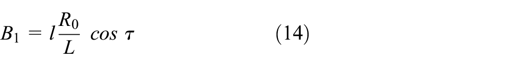
The constant differential pressure valve is a crucial hydraulic component of the fuel metering device. Its stability and dynamic characteristics have a direct impact on the overall performance of the control system. A design theory for the constant pressure difference regulating mechanism was revealed in Zhao et al., 3 with two core control gains designed using the frequency domain analysis method. The structure of the constant pressure difference valve system was analyzed in Wei et al., 4 and the transfer function of the valve was established. They analyzed the stability and calculated the steady-state error of the unit under step input. However, there are few studies on the dynamic characteristics of the differential pressure valve in the process of searching for literature. The dynamic mathematical model of the pressure difference valve was derived in Yang et al. 5 according to the nonlinear differential equation of the pressure difference valve and the small deviation linearization method.
This paper discusses the constant pressure difference mechanism, including the fuel pump, which is an angle-type axial piston pump. When analyzing the characteristics of the constant pressure differential valve, the fuel pump characteristics should be considered. The mathematical model of a hydraulic axial piston pump developed to replicate the dynamic behavior of the swash plate for Prognostic and Health Management applications was presented in the document. 6 Some of the conclusions guide the design of high-pressure fuel pumps. The piston has a tapered rotor spherical axial swash plate and was taken as the research object and developed research of calculation of slipping shoe and the swash plate of the lubrication circular leakage. 7
An electro-hydraulic servo valve-controlled fuel metering device can be seen as an electro-hydraulic position servo system. There are many kinds of literature on this topic. The high-frequency position servo control of hydraulic systems with proportional valves using the back-stepping control method was researched in Li et al. 8 A robust proportional-integral-derivative (PID) controller was computed for adjusting the position of the piston of an experimental hydraulic servo actuator under different pressure operating conditions. 9 To solve the problems of slow response, poor precision, and weak anti-interference ability in hydraulic servo position controls, a Kalman genetic optimization PID controller was designed to reduce the amplitude fluctuations and the influence of external disturbances on the system. 10 However, the PID controller is still the first choice in practical engineering applications because of its simple structure, good stability, reliable operation, and convenient adjustment. In this paper, PID is used as the controller of single and double-chamber controlled metering systems.
The paper describes a controlled differential pressure valve, which works with a piston pump. This valve is different from the commonly used scavenger constant differential valve and requires a thorough analysis of its structure and working principle. The paper establishes a mathematical model of a constant pressure differential valve and analyzes its time and frequency domain characteristics. The literature lacks consideration of the influence of tank pressure on the modeling of single and double-chamber control. Additionally, the definition of load flow and load pressure in double chamber control systems is questionable.
This paper is structured as follows. Section “Introduction of fuel metering system” introduces the fuel metering systems. In Section “Characteristics analysis of constant pressure differential valve assembly,” a mathematical model of the constant pressure differential valve assembly is established, and its time and frequency domain characteristics are analyzed. Section “Modeling of two kinds of fuel metering mechanisms” establishes mathematical models of single and double-chamber controlled metering valves, and verifies the accuracy of the models using measured data. Section “Analysis of closed-loop characteristics of metering valve with double and single chamber control” compares and analyzes the results of the closed-loop characteristics. Finally, the conclusions are summarized in Section “Results.”
Introduction of fuel metering system
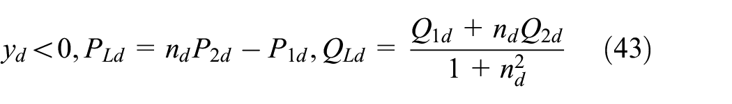
Figure 3 shows the double chamber-controlled metering structure is similar to the one in the CFM56-7 engine. It includes an Electro-hydraulic servo valve (EHSV), a fuel metering valve, and a constant pressure differential valve assembly, which comprises a fuel pump and a differential pressure valve. The fuel metering valve’s spool displacement is controlled by an EHSV that receives electrical commands, which meter the fuel flow to the required value. The pump’s discharge flow is regulated by a flow control mechanism connected to the differential pressure valve. A switching valve is used to switch between the two electro-hydraulic servo valve oil circuits, reducing the impact of valve failure on the fuel supply. Figure 4 depicts the signal chamber-controlled metering structure. In this mechanism, one control chamber’s pressure of the fuel metering valve maintains a fixed valve, while the other control chamber’s pressure undergoes modulation by the electro-hydraulic servo valve, which receives the command signal from the electronic controller. The constant pressure differential valve guarantees the fuel pressure difference before and after measurement remains constant.
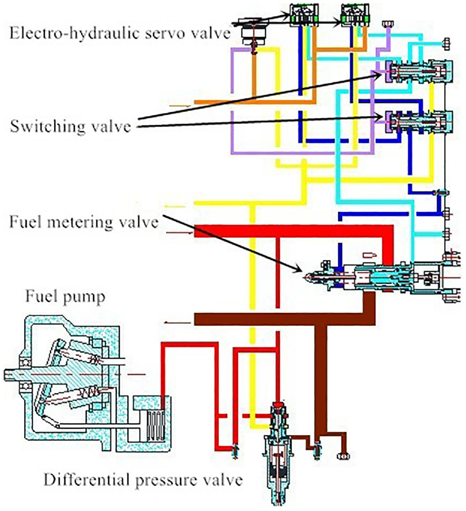
Schematic diagram of double chamber-controlled metering structure.

Schematic diagram of signal chamber-controlled metering structure.
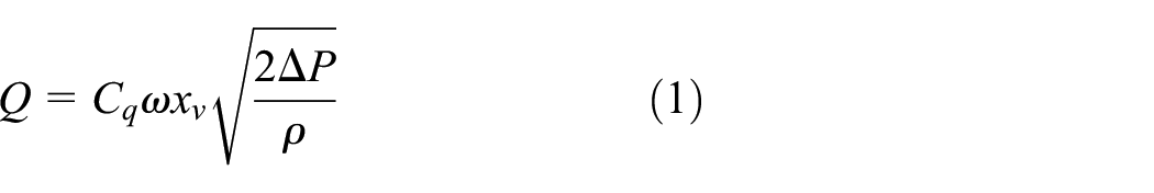
The fuel flow
Characteristics analysis of constant pressure differential valve assembly
Figure 5 displays the assembly drawing of the differential pressure valve, while Figure 6 illustrates the fundamental diagram of a fuel pump. Together, they form a constant differential pressure valve assembly. A portion of the fuel pump discharge flow and metered fuel flow is directed into the differential pressure valve, with the action areas being

Assembly drawing of the differential pressure valve.
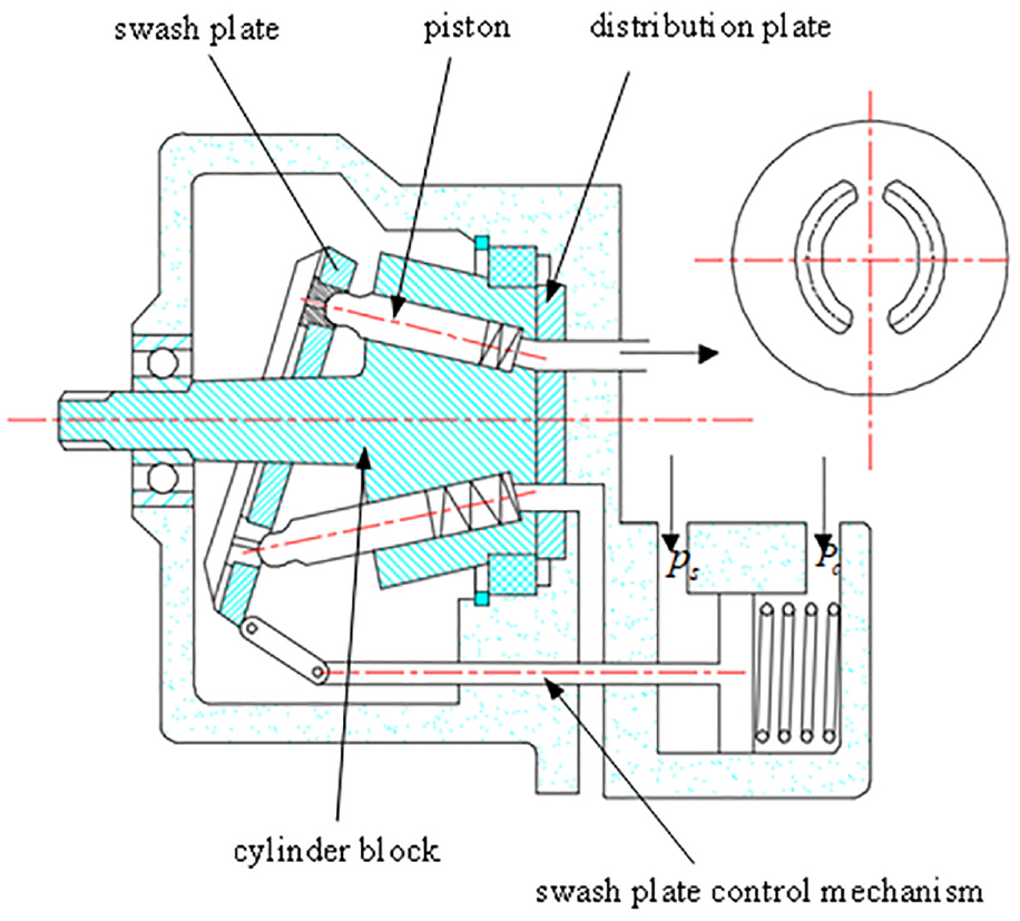
Fundamental diagram of the fuel pump.
The mathematical model of constant pressure differential valve assembly
The mathematical model is established based on an understanding of the working principle of the constant pressure differential valve assembly.
(1) The force equation of valve spool of constant pressure difference valve
The forces acted on the valve spool of the differential pressure valve include the forces acted on the valve spool by the metered and unmetered fuel, the steady-state hydrodynamic force, the force of spring compressed in advance, and viscous friction force. The equation of force balance is established as follows

where

where
(2) The mathematical model of the fuel pump
The fuel pressure within the control chamber of the fuel pump is determined by the fuel flow through the constant pressure difference valve entry or outlet in the chamber. The angle of the fuel pump’s swash plate is adjusted accordingly. Through the swash plate inclination angle, one can analyze the discharge flow and pressure of the fuel pump. Analysis of the fuel pump control chamber pressure is based on the assumption that the fuel pressure is uniform and that the inertia and viscosity effects of the fuel in the control chamber are negligible when compared to the fuel pressure.
① The fuel pressure in the control chamber is expressed by the following equation,
where
It can be seen from Figure 7 that the relationship between the pistons displace

where

where

Schematic diagram of swash plate position control mechanism.
It can be concluded that the relationship between piston displacement and swash plate inclination angle
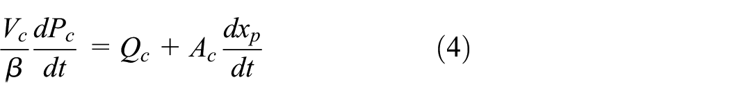
The flow into the control chamber of the constant pressure difference valve can be expressed as
where
The formula (4) can be reformed as,

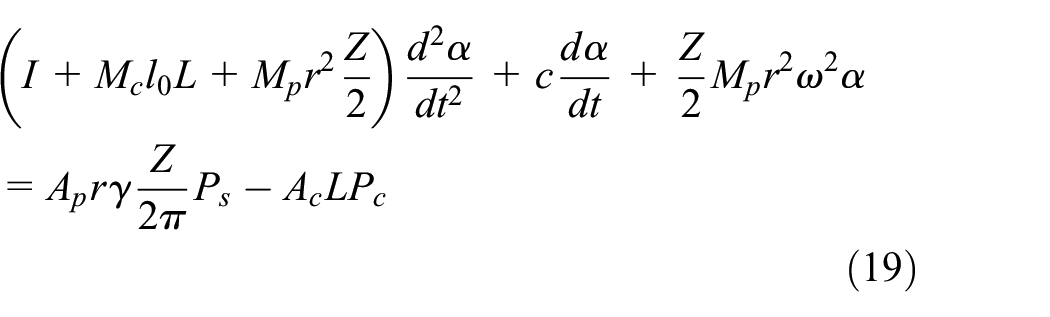
② The pressure of the control chamber drives the movement of the swash plate, and the torque balance equation of the swash plate is

where
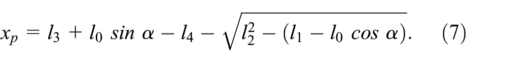
The distance between the action point of the piston force on the swash plate surface and the swash plate shaft can be expressed as

where


The motion equation of the variable mechanism is

The following formula can be obtained

The net force of the slippers and pistons assembly on the swash plate is expressed as

The fuel pressure

The expressions of the above forces are introduced into equation (9), then
③ The equation of pressure in the fuel transmission pipeline is established

Assuming that the input speed of the fuel pump is constant, then the discharge flow is

and

where
The mathematical model of constant pressure differential valve assembly is obtained

The state variables are
Time domain characteristic analysis of constant pressure differential valve
After the mathematical model of the constant differential pressure valve is established, the simulation analysis of the import and export of the constant differential pressure valve is carried out. The rated pressure of the fuel pump is 7 MPa. The simulation is first carried out under the condition that the pressure difference between metered and unmetered is constant. It can be seen from Figure 8 that the discharge pressure of the fuel pump can reach the rated pressure when the pressure difference is constant, and its stable time is less than 1 s without steady-state error.

The discharge pressure of the fuel pump when the pressure difference is constant.
Then the simulation analysis is carried out under the condition that there is a step fluctuation signal of the pressure unmetered of the constant differential pressure valve, and the amplitude of the step signal is 5 bar. As shown in Figure 9, the discharge pressure of the fuel pump reaches the steady-state value 6.5 MPa after 0.8 s at the third second of the simulation. After the step signal disappears, the discharge pressure of the fuel pump returns to 7 MPa, the adjustment time is 0.8 s, and the steady-state error is 0 MPa. The changed value of pump discharge pressure is consistent with the amplitude of the step signal.

The discharge pressure of the fuel pump when a negative step fluctuation signal considered.
The simulation analysis is carried out under the situation that the pressure unmetered changes as a ramp signal. As shown in Figure 10, the discharge pressure of the fuel pump follows the slope pressure change after the third second with lags of 0.3 s. After the slope change stabilizes, the discharge pressure of the fuel pump reaches a steady state after 0.5 s, and the steady-state error is 0 MPa.
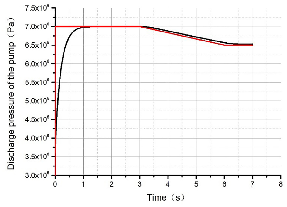
The discharge pressure of the fuel pump when a ramp fluctuation signal considered.
The simulation analysis of the fuel-metered pressure fluctuation of the constant differential pressure valve is carried out similar to the above analysis. The simulation analysis is carried out under the condition that there is a step fluctuation signal of the fuel metered pressure by the constant differential pressure valve, and the step signal amplitude is 5 bar. As shown in Figure 11, the discharge pressure of the fuel pump reaches the steady-state value after 0.7 s at the third second of the simulation and the increment value of the pump discharge pressure is equal to the amplitude of the step signal that is 5 bar. After the step signal disappears, the discharge pressure of the fuel pump returns to 7 MPa with an adjustment time of 0.7 s and a steady-state error of 0 MPa. Then simulation analysis is carried out under the condition that the fuel-metered pressure by the constant differential pressure valve changes as a ramp signal. As shown in Figure 12, the discharge pressure of the fuel pump follows the slope pressure change after a lag of 0.3 s. The discharge pressure of the fuel pump reaches a steady state after 0.5 s when the slope change is stable, and the error is 0 MPa.

The discharge pressure of the fuel pump when a positive step fluctuation signal considered.

The discharge pressure of the fuel pump when a ramp fluctuation signal considered.
Frequency domain characteristic analysis of constant pressure differential valve
The frequency domain analysis of the constant pressure differential valve assembly is carried out by drawing the Bode diagram of the system.
A system is established with a constant pressure differential valve and a fuel pump. The input to the system is the pressure difference across the constant pressure valve and the output is the discharge pressure of the fuel pump. A sine wave signal with a predetermined frequency is applied to the input, and the output is connected to a Fourier module. By matching the frequency of the sine wave and the Fourier module, the amplitude and phase of each working frequency can be measured. The Bode diagram calculation results are shown in Table 1 and Figure 13. During the frequency domain analysis, the amplitude suddenly increases after 150, and the phase jumps between −180° and 180°. This means that the normal operating frequency range of a constant pressure differential valve cannot exceed 150.
Calculation results of Bode diagram.


Logarithmic amplitude and phase frequency curve.
Based on the time domain analysis, it has been found that the constant differential pressure valve and variable fuel pump system have the ability to accurately regulate the pump discharge pressure in order to achieve a new equilibrium state even when there is a differential pressure fluctuation. Furthermore, the system can restore the original discharge pressure of the pump after the pressure fluctuation subsides. In the frequency domain analysis, it was discovered that the normal operating range of the constant pressure differential valve is below 150 Hz, which is higher than the frequency bandwidth of single and double chamber fuel metering systems, so it can ensure the rapid response of pressure difference adjustment to meet the demand of fuel metering.
Modeling of two kinds of fuel metering mechanisms
Through the structural analysis of two kinds of fuel metering mechanisms, it is found that the main components are electro-hydraulic servo valve and metering valve. It is necessary to model and analyze them respectively.
Modeling of an electro-hydraulic servo valve
The electro-hydraulic servo valve transfer function considers the current signal as input and spool displacement as output. This function assumes that the liquid in the electro-hydraulic servo valve is incompressible and neglects the dynamic response of the torque motor, force-displacement converter, and power amplifier with pre-stage, treating them as a spring-damping-mass system. The transfer function can be expressed as an equation

where
Model of single chamber controlled metering valve
The valve-controlled mechanism refers to the link from the electro-hydraulic servo valve spool displacement to the displacement of the metering valve. One end of the metering valve spool is subjected to the force of the constant pressure fuel, and the other end is subjected to the force of the fuel from electro-hydraulic servo valve.
This section deduces the linear model of a single chamber-controlled metering valve from three equations which are the flow-pressure characteristic equation of the electro-hydraulic servo valve spool, the flow continuity equation of the asymmetric cylinder, and the force balance equation of metering valve spool.
Modeling assumptions
The electro-hydraulic servo valve is ideal, that is, (1) The throttling edge is an absolute acute angle with no-radial clearance and no leakage, (2) Symmetrical orifice means (3) Matched throttle orifice means (4) The flow coefficients of the orifice are equal means
The setting of fuel characteristics, (1) The fuel flow through the orifice of the electro-hydraulic servo valve is an ideal fluid, (2) The fuel in the metering valve is compressible, (3) The density of the fuel is constant.
The fuel feeding pressure is constant.
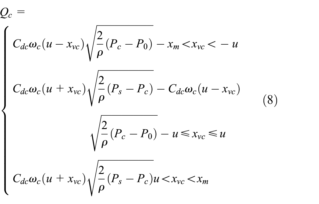
Following the power matching principle of the valve and the cylinder, the load pressure
Valve-controlled metering valve
① Flow-pressure characteristic equation of metering valve
Flow into the rodless chamber of the metering valve

where
The Taylor expansion of the equation (26) is carried out near the working point of the electro-hydraulic servo valve, and the second and higher order terms are neglected. The following expression is obtained


where

Carry out the Laplace transform of the above equation (26) and the incremental transfer function of load flow is obtained

② Flow continuity equation of metering valve
Due to the spool of the metering valve doing a small amount of movement, then the equation
Then the continuous flow equation of the rodless chamber is
that is
The Taylor expansion of equation (32) is carried out near the working point of the metering valve and ignores the second and higher-order terms

Then the following equation (34) is got

Carrying out the Laplace transform of (34), it can be obtained

③ Force balance equation of metering valve spool
The spool of the metering valve is mainly affected by the pressure of two control chambers, spring force, friction force, and inertia force.

where
The Taylor expansion of equation (36) is carried out, and ignore the second and higher-order terms


Carrying out the Laplace transform of equation (38), it can be obtained

Then the following equation (40) is got

④ Equation of single chamber metering valve controlled by an electro-hydraulic servo valve
Combining equations (30), (35), and (40), the following expression can be obtained

Model of double chamber controlled metering valve
Modeling assumptions
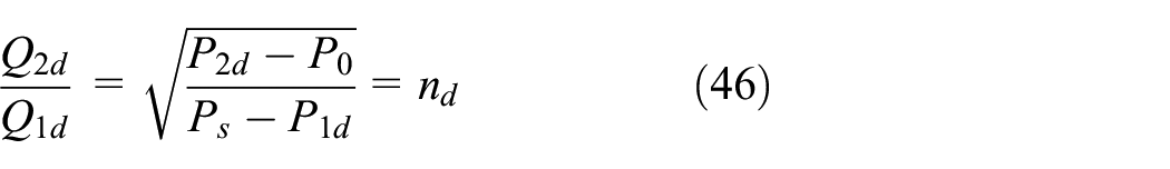
The modeling assumptions of double chamber controlled metering valve are consistent with that of single chamber controlled metering valve. Following the power of valve and cylinder matched principle, the load pressure

where
Valve-controlled metering valve
① Flow-pressure characteristic equation
The fuel flow into the rodless chamber of the metering valve

The fuel flow out of the metering valve rod end chamber

where
The following equation (46) can be obtained from the above equations and the assumement
Therefore

Considering the definition of load pressure and load flow, yield the following equation


Substituting equations (47)–(49) into equation (46), equations (50) and (51) can be obtained


So
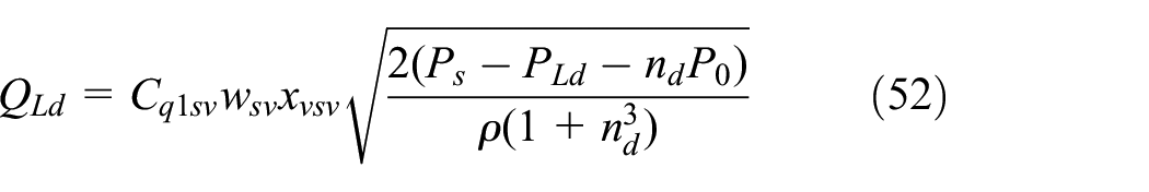
The Taylor expansion of equation (52) is carried out, and ignore the second and higher-order terms


where


Carrying out the Laplace transform of equation (54), yield the following equation

② Flow continuity equation
The initial volume of the metering valve rodless cavity and rod end chamber is defined as
The continuous flow equation of a rodless chamber is

The continuous flow equation of the rod end chamber is

where
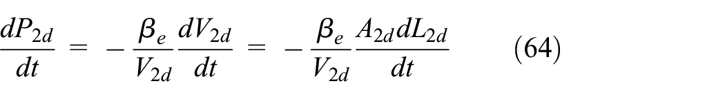
And then


It can be deduced from the above equations


where

Substituting equation (65) into equation (62), then
Substituting equations (66) and (67) into equation (42), then
where

Taylor expansion of equation (68) is performed near the working point and ignores the second-order and higher-order terms


Carrying out the Laplace transform of equation (71), the following equation is obtained

③ Force balance equation of metering valve spool
The spool of the metering valve is mainly affected by the force produced by the fuel pressure of the control chambers, spring force, friction force, and inertia force.


where
The Taylor expansion of equation (74) is carried out, and ignore the second and higher-order terms


Carrying out the Laplace transform of equation (76), we can get,

and then

④ Equation of double chamber metering valve controlled by an electro-hydraulic servo valve
Combining equations (57), (72), and (78), the following expression can be obtained

To verify the accuracy of the double chamber controlled metering valve model, the fuel flow calculated of the model and the test data are compared under the same input signal. If the fuel flow of test data is

Fuel flow comparison of the simulation model and test data for double chamber-controlled metering valve.
Comparison results of test data and simulation model for double chamber controlled metering valve.

Among the tested 21 steady-state points, the steady-state errors of four steady-state points are more than 2%, and the other steady-state points can meet the requirements that the test data of fuel metering device and model simulation data are within the error range of 2% under typical working conditions. Therefore, the established mathematical model is accurate and can be used for the closed-loop characteristic analysis.
Analysis of closed-loop characteristics of metering valve with double and single chamber control
The dynamic and static characteristics of the two mechanisms are compared and analyzed by placing them in the closed-loop control system with a PID controller. The closed-loop characteristic analysis is mainly carried out from the time and frequency domain. The steady-state and dynamic performance under different controller parameters can be obtained in the time domain, and the changes in amplitude stability margin, phase stability margin, and bandwidth can be seen in the frequency domain.
Stability analysis of the system
The single-cavity proportional control parameters P = 1, 10, 20, 30, and 40 dual-cavity proportional control parameters P = 1, 10, 15, 20, 30, and 40 are set, and the Nyquist diagram of the closed-loop transfer function is drawn.
It can be seen from Figures 15 and 16 that the amplitude-frequency characteristic curves of the single-cavity and double-cavity control systems do not surround the (−1, 0i) points. Therefore, according to the Nyquist stability criterion, the single-cavity and double-cavity proportional closed-loop control systems are stable.

The closed-loop Nyquist diagram of single-controlled metering valve under different control parameters.

The closed-loop Nyquist diagram of double-controlled metering valve under different control parameters.
Time domain analysis
The dynamic performance of single and double chamber-controlled metering valves is compared in time domain, and the main indexes are overshoot, regulation time, and steady-state error.
The steady-state error mainly refers to the difference between the displacement of the single and double chamber-controlled metering valve spool and that of the command signal. Record the steady-state error of the single chamber control system after running 10 s with the closed-loop system under different proportional control parameters P = 1, P = 10, P = 20, P = 30, P = 40 and the steady-state error of the double chamber control system after running 10 s under different proportional control parameters P = 1, P = 10, P = 15, P = 20, P = 30, P = 40. The results are shown in Table 3 below.
The steady-state error of single and double chamber control systems with different proportional control parameter.

The technical requirements of a steady-state error of 0.5% are satisfied in two closed-loop systems with control parameters used in the test and appropriately increasing the proportional control parameter can reduce the steady-state error. The steady-state error of the single chamber-controlled metering valve mechanism with a maximum value of 0.194 mm and minimum value of 1.25e-6 mm is smaller than that maximum value of 0.302 mm and minimum value of 1.95e-6 mm of double chamber-controlled metering valve mechanism under the same controller parameters.
Under the same displacement command signal, different controller parameters (P = 1, 10, 20, 30, and 40) are set in the nonlinear model of single chamber control metering valve position closed loop, and different controller parameters (P = 1, 10, 15, 20, 30, and 40) are set to double chamber control metering valve position closed loop and then run the model respectively.
As shown in Figures 17 and 18, and Table 4, the adjustment time of single and double-chamber controlled metering mechanisms gradually decreases along with the proportional coefficient of the controller increases and the dynamic response becomes faster. The extension adjustment time with a maximum value of 2.654 s and minimum value of 0.141 s of single chamber controlled metering valve mechanism is more than that of double chamber controlled metering valve mechanism with a maximum value of 1.987 s and minimum value of 0.105 s, and retraction adjustment time with maximum value 2.418 s and minimum value 0.134 s of single chamber controlled metering valve mechanism is less than that of double chamber controlled metering valve mechanism with maximum value 2.65 s and minimum value 0.142 s with the same controller parameters. So, the symmetry of extension and retraction motion of single chamber-controlled metering valve is better than that of double chamber-controlled metering valve when appropriate values of the controller are selected. The extension overshoot with a maximum value of 3.564% and retraction overshoot with a maximum value of 1.391% of single chamber-controlled metering valve mechanism is smaller than double chamber-controlled metering valve mechanism with a maximum extension overshoot 6.04% and maximum retraction overshoot value 1.17%.

Servo tracking results of a closed loop with single chamber control under different controller parameters.

Servo tracking results of a closed loop with double chamber control under different controller parameters.
Step performance data of single and double chamber control system.

Frequency domain analysis
The frequency domain dynamic performance of two fuel metering mechanisms with different proportional controller parameters is researched. The main performance index is bandwidth. Different controller parameters (P = 1, 10, 20, 30, and 40) and (P = 1, 10, 15, 20, 30, and 40) are respectively set for the linear model of single chamber control metering valve position closed loop and linear model of the double chamber control metering valve position closed loop to obtain the amplitude-frequency and phase-frequency characteristics curves.
As shown in Figures 19 and 20, and Table 5, the bandwidth of the extension motion of the single and double chamber control metering valve is greater than that of the retraction motion. Under the same proportional control parameter, the bandwidth of the double chamber control metering valve extension motion system is greater than that of the single chamber controlled system, but the bandwidth of retraction motion of double chamber control metering valve is less than that of a single chamber control metering valve system.
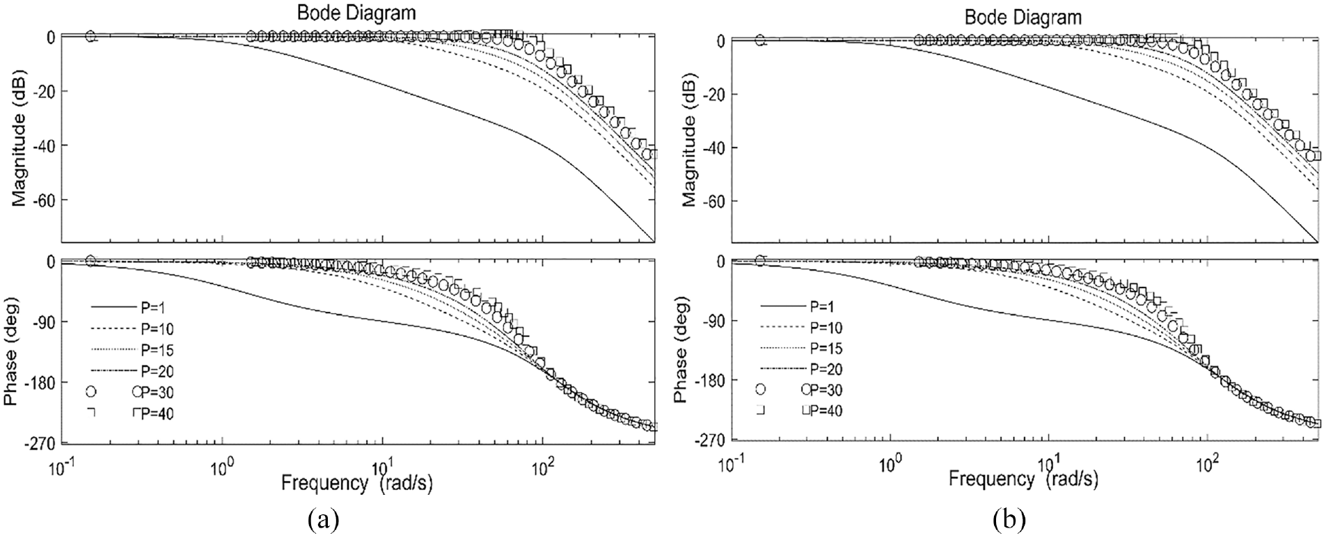
Closed loop Bode diagram of double chamber-controlled metering valve: (a) extension movement and (b) retraction movement.

Closed loop Bode diagram of single chamber-controlled metering valve: (a) extension movement and (b) retraction movement.
Closed loop extension movement and retraction motion characteristic table of single and double chamber control system.

Results
The main purpose of this article is to analyze the time domain and frequency domain characteristics of constant pressure valve assembly and compare the closed-loop characteristics of the two metering mechanisms. Firstly, the mathematical model of constant pressure differential valve assembly (including the fuel pump and constant pressure differential valve) is established, and time domain and frequency domain characteristics are analyzed. The adjustment time is 0.5 s and the steady-state error is 0 MPa when the discharge pressure of the pump fluctuates and the dynamic characteristics are almost identical under the condition of pressure fluctuation after metering. After frequency domain analysis of it, the bandwidth is not less than 150 Hz meeting the stability requirements. Secondly, the mathematical models of single and double-chamber controlled fuel metering mechanisms are established. Finally, the characteristics of the two kinds of metering mechanisms are compared and analyzed under the same control method in the time and frequency domain. The adjustment time is 0.5 s and the steady-state error is 0 MPa when the discharge pressure of the pump fluctuates and the dynamic characteristics are almost identical under the condition of pressure fluctuation after metering. In terms of steady-state error, the steady-state error of a single chamber control metering valve mechanism with a maximum value of 0.194 mm and minimum value of 1.25e-6 mm is smaller than that maximum value of 0.302 mm and minimum value of 1.95e-6 mm of double chamber controlled metering valve mechanism under the same controller parameters. The bandwidth of the extension motion of the single and double-chamber controlled metering valve system is greater than that of the retraction motion. Under the same proportional control parameter, the bandwidth of the double chamber controlled metering valve extension motion system is greater than that of the single chamber extension motion system.
Footnotes
Appendix
Handling Editor: Chenhui Liang
Declaration of conflicting interests
The author(s) declared no potential conflicts of interest with respect to the research, authorship, and/or publication of this article.
Funding
The author(s) received no financial support for the research, authorship, and/or publication of this article.