
Abstract
The nonlinear load of the axle box bearing and the spatially coupled relationship of vehicles have seldom been considered in the dynamic modeling of vehicle–track systems in recent years. Therefore, based on the time-varying nonlinear contact load of an axle box bearing, a vehicle spatially coupled dynamic model is established. Subsequently, the vehicle–track spatially coupled dynamic model is established by the dynamic coupled relationship between the wheel and rail. Finally, the vehicle wheelset testbed is set up to verify the correctness of the theoretical model. Experimental results show that (1) the vibration of an axle box has a strong nonlinear coupled relationship. The axle box vertical amplitude aroused by lateral alternating load is approximately 0.108 mm, which was approximately 22.2% of the lateral vibration and (2) the lateral displacement and acceleration errors of axle box between the simulation and experiment are about 5.7% and 6.9%, respectively, which validates the theoretical model. The vehicle–track spatially coupled dynamic model accurately reflects the vibration characteristics of locomotives under track irregularity and provides theoretical support for the design of key components, such as axle box bearings.
Keywords
Introduction
Axle box bearing is the pivotal component of the vehicle travel mechanism. The complex dynamic loads between the vehicle frame and the track test the performance of the axle box bearings. In addition, the operational performance of axle box bearings has significant impact on the safety and reliability of the train. The failure of axle box bearings directly causes train safety accidents, such as hot axle and derailment. So, it is of great theoretical and engineering significance to research intensively the mechanical properties and structural design of the vehicle and crucial parts, which takes into account the nonlinear contact mechanical properties of the axle box bearing.
Great deals of achievements have been made by researchers on the structural design and dynamics of the vehicle–track system. Scholars have given more attention to the dynamic characteristic of complete vehicle or vehicle-track system, without taking into account the effect of nonlinear contact force of the axle box bearings.1–5 Based on the modular method, a three-dimensional dynamic vehicle–track coupled dynamics was established by Liu et al., 1 considering the large creep of wheel–track contact. A finite element model of the vehicle was calibrated using experimental modal parameters. 2 Sadeghi et al. 3 studied the effect of track irregularities on the wheel–track dynamic force. Uzzal et al. 4 primarily studied the dynamic characteristics of track and wheelset subjected to impact loading. Zhai et al. 5 have performed lots of research on the wheel–rail force and dynamic characteristics of the key frame using the distributed parameter method. In recent years, Chen et al.6–8 developed several locomotive dynamics models by considering the dynamic effects from the mechanical transmission subsystem based on the classical vehicle–track coupled dynamics model proposed by Zhai. Several scholars have studied the vibration characteristics of vehicles, wheel tracks, and the ground and their mutual influence on each other, through experimental tests.9–11 Jin et al. 9 focused on the vibration characteristics of vehicles, considering the wear mechanism of the wheel. The vibrational characteristics of high-speed trains were studied by field experiments under 350 km/h in China. 10 The relationship between ground vibration and the structural parameters of a locomotive and track was studied by Zhai et al. 11 through field tests of ground vibration. Scholars have also conducted research on vehicle–track coupled dynamic characteristics on curved track.12,13 In addition, researchers have researched the track modeling to investigate the dynamic characteristics of the vehicle wheelsets.14–18 The effect of the track structure parameters on dynamic characteristics was analyzed using the finite element method. 15 Di Gialleonardo et al. 17 built a series of track models: the rigid track model, detailed finite element model, and local simplified model. Song et al. 18 used the sliding window method and proposed a fast solution in order to improve the calculation efficiency of the wheel–rail coupled model.
Although these studies of vehicle–track coupled dynamics achieved fruitful results, the spatially coupled relations of vehicle dynamics and theoretical modeling of axle box bearing have been ignored in the vehicle–track dynamics model.1,2,4,5,12,13 This simplification influences the exactitude on vehicle–track coupled dynamics system and cannot acquire directly the mechanical properties of critical components. What is more, research on vehicle–track coupled dynamics considering the spatially coupled relationships of axle box bearings have rarely been reported.
In summary, the research objectives of this article are as follows: (1) to establish the nonlinear contact model of axle box bearings and nonlinear load of bearings, and to obtain the spatially coupled relationship of vehicle vibration; (2) to obtain the vehicle coupled dynamics model that includes the carbody, bogie, axle box bearing, and wheelsets based on the lumped mass method and subsequently establish the vehicle–track coupled dynamics model based on the wheel–track coupled relationship and distributed parameter track model; (3) to verify the vehicle coupled model predictability by wheelset experiments. In this article, the vehicle dynamic characteristics under track irregularity excitation and the load law of the axle box bearing system are reported in order to inform the structural and lubrication design of axle box bearings.
Materials and methods
A vehicle–track system consists of carbody, bogie, axle box, wheelset, primary spring suspension, secondary suspension, and rail (Figure 1). The carbody is connected to the frame through the secondary suspension, and the frame is connected to the axle box through the primary suspension. The axle box and the bearing outer ring are connected under an interference fit, and so do the inner rings and the wheelset axle. The rails are connected with sleepers through the fastener. In the process of train operation, the excitation is mainly caused by nonlinear contact of the wheel and rail. The disturbance force is transmitted to the wheelset, axle box bearing, bogie frame, and carbody successively, and to the rails and sleepers in turn.
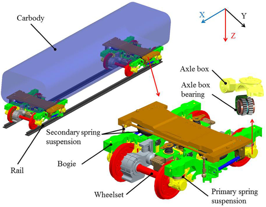
The structural schematic of the vehicle system.
Theoretical model of vehicle–track coupled dynamics
Based on the vehicle–track coupled dynamics model proposed by Zhai and colleagues5,19,20 (which is usually called as “Zhai model” worldwide), the spatially coupled relationship of the vehicle vibration is established by the lumped parameter model. Vehicle bogie models are composed of two wheelsets, one bogie frame, and primary and secondary suspensions. The equivalent mechanical model of vehicle–track coupled dynamics is illustrated in Figure 2. The vertical dynamics model is illustrated in Figure 2(a), where PLY1 and PLY2 are the vertical equivalent loads on the front and rear wheelsets, respectively; m1, m2, m3, and m4 are the equivalent masses of the carbody, bogie, axle box, and wheelsets, respectively; Z1, Z2, Z3, and Z4 are the vertical displacements of the carbody, bogie, axle box, and wheelsets, respectively; KZ1 and KZ2 are the vertical stiffness of primary and secondary suspensions, respectively; CZ1 and CZ2 are the vertical damping coefficients of primary and secondary suspensions, respectively; Cbz is the vertical damping coefficient of the axle box bearings; and Fr and Fa are the vertical and lateral nonlinear contact loads of the axle box bearings, respectively.
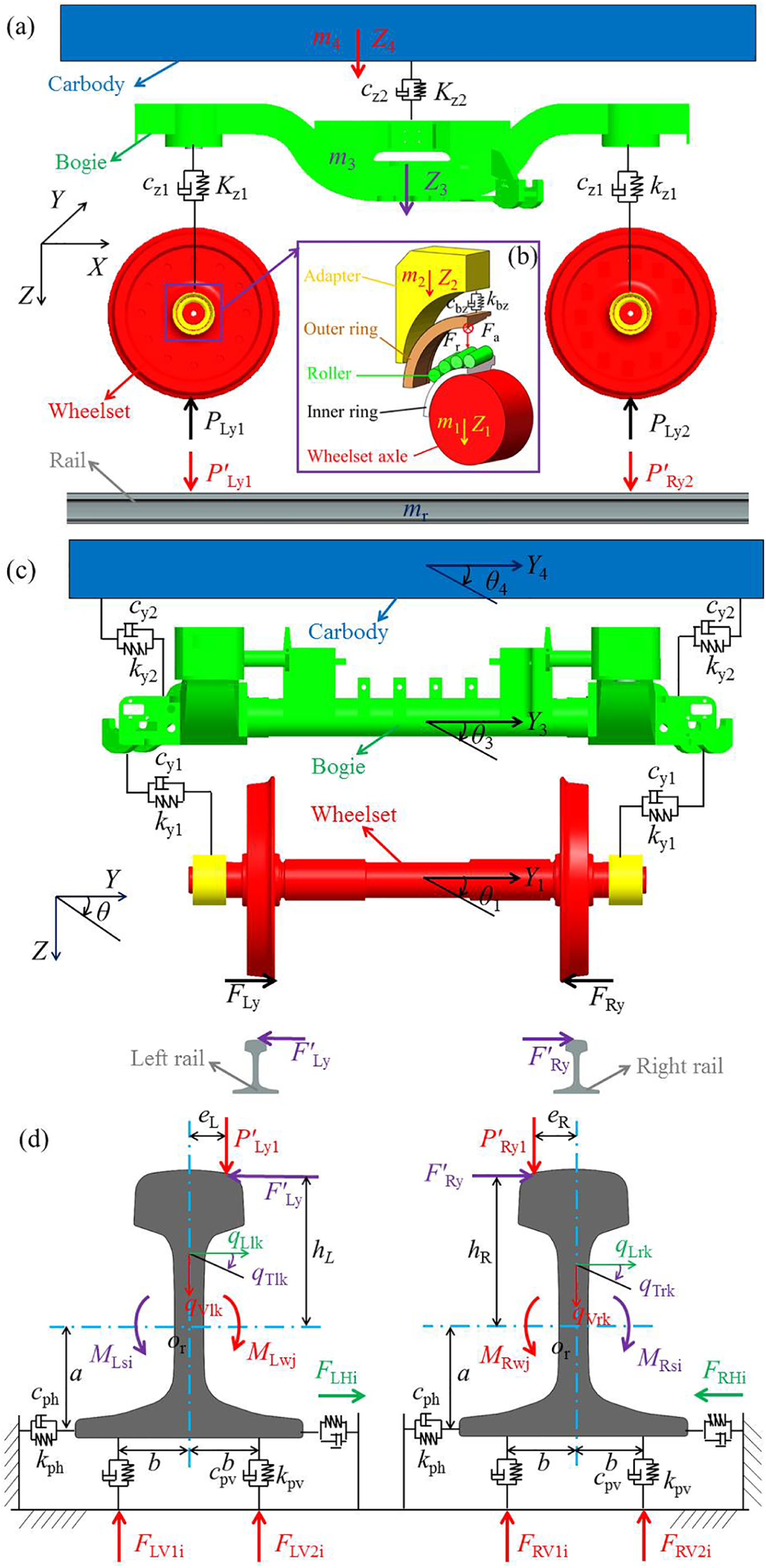
Coupled dynamics model of vehicle track: (a) vertical dynamics model; (b) mechanics model of axle box bearing; (c) lateral dynamics model; (d) equivalent mechanical model of the ballastless track.
The lateral vehicle–track coupled dynamics model is illustrated in Figure 2(c), where Y1, Y2, Y3, and Y4 are the lateral displacements of the carbody, bogie, axle box, and wheelsets, respectively; θ1, θ2, θ3, and θ4 are the pendulum displacements of the carbody, bogie, axle box, and wheelsets, respectively; Ky1 and Ky2 are the lateral stiffness of primary and secondary suspensions, respectively; Cy1 and Cy2 are the lateral damping coefficients of primary and secondary suspensions, respectively; and FLy1 and FRy2 are the lateral creep forces of the tracks on wheelsets 1 and 2, respectively.
The equivalent mechanical model 19 of the ballastless track is illustrated in Figure 2(d), where qVlk, qLlk, and qTlk are the vertical regular formation coordinate of the tracks, the lateral regular formation coordinate of the tracks, and the torsional regular formation coordinate of the tracks, respectively; Or is the center of track torsion; e is the lateral distance between the vertical force of the track and the center of rotation; h is the vertical distance between the track force acting on the center of rotation; a is the vertical distance between the wheel/track contact point and the torsional center; b is the lateral distance between track neutral surface and the reaction point of the track’s left or right fulcrums; and FV1i and PV2i are the counterforces of the left and right pivots of the track, respectively.
Nonlinear coupled relationship of the dynamics model
Spatially coupled relationship of axle box bearings’ vibration
An axle box device is a device that links the wheelset and the frame, bears the weight of the locomotive, and transfers the force in all directions. The bearings are mounted in the axle box. The bearing outer rings and the axle box are connected under an interference fit, and so do the inner rings. The axle box and the outer ring of the bearing are set as a node, while the inner race of the bearing ring and the wheelset of the locomotive together are taken as a node. The nonlinear load of the bearing is obtained by the vibration displacement of the two nodes. The rigid ring hypothesis was adopted in this article, so the displacement of the outer ring with respect to the inner ring can be divided into radial displacement δr, axial displacement δa, and rotation angle θ. The structure and stress indication of an axle box are illustrated in Figure 3.

Force diagram of wheel bearings.
Under the combined action of radial load, axial load, and torque load, the total radial displacement (δri), the axial total displacement (δai), and the total displacement (δni) along the normal contact direction of the inner raceway contact can be obtained at the ith roller as follows

where R1 is the vertical distance from roller center to bearing center line, R2 is the horizontal distance from roller center to bearing center line. The contact load between the ith roller and the raceway is

where K is the contact stiffness of the roller raceway and H(δwn) is the contact state judgment function

The contact stiffness, K, 21 between the roller and raceway is

where αi, αe, and αf are the contact load angles between the cone roller, the internal raceway flange, and the external raceway flange, respectively. Dw is the equivalent diameter of the bearing roller and l is the effective contact length of the roller.
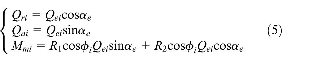
The radial load (Qri), axial load (Qai), and overturning moment (Mmi) of the ith roller are
The relationships between the overall deformation of the bearing and the displacement of the vehicle components are

The radial and axial component vectors of the contact load of the bearing roller are offset with the external loads. The response load of the two column bearings is superposed, and the balance equations of the bearings can be deduced by the balance of the force and moment. The nonlinear load equation of the axle box bearings can be obtained using equations (1), (2), (5), and (6)
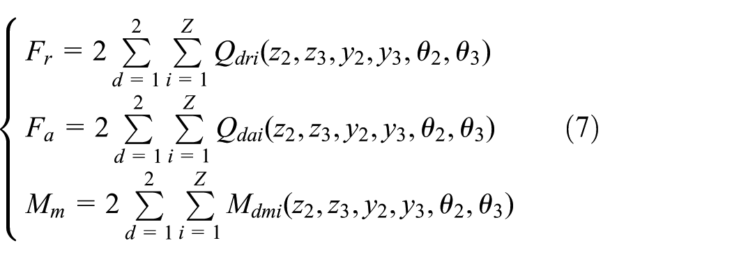
where d is the row number of the bearing; Z is the number of the single-row rollers; and Fr, Fa, and Mm are the radial, axial, and torque loads on the axle box bearing, respectively.
Dynamic coupled relationship of wheel and rail
Since both the wheel and rail are considered elastic bodies, the interaction between them can be described by classical Hertz contact theory. The left and right wheel/rail normal contact forces are PLy and PRy, respectively, which are determined by the nonlinear contact theory.22–24 When the track irregularity is considered in the vehicle operation, the track irregularity value should be included in the calculation of the elastic compression. The normal wheel–track force 19 is then

where G is the wheel/track contact constant; ZwL(t) and ZwR(t) are the vibration displacements of the left and right wheels, respectively; ZrL(t) and ZrR(t) are the vibration displacements of the left and right tracks, respectively; and ZpL(t) and ZpR(t) are the values of the left and right track irregularities, respectively.
Kalker linear creep theory is only suitable for small creep and spin. Therefore, the nonlinear theory can be used to correct the creep force of wheel and rail, so that the calculation of creep force can be widely applied to cases with arbitrary creep rates. The wheel–track longitudinal creep force (Fx), transverse creep force (Fy), and rotational creep torque (Mz) can be expressed as 19

where ξx, ξy, and ξφ are the longitudinal, transverse, and spin creep, respectively; ε is the correction factor; and fij represents the coefficient of creep and is determined by the lower formula.
Vehicle–track coupled dynamics equation
According to the equivalent model of the spatially coupled dynamic equation of the vehicle, the following dynamic equations can be obtained.
The vertical degrees of freedom (DOFs) are as follows

The lateral DOFs are as follows

The overturning DOFs are as follows

Calculation of dynamics parameters
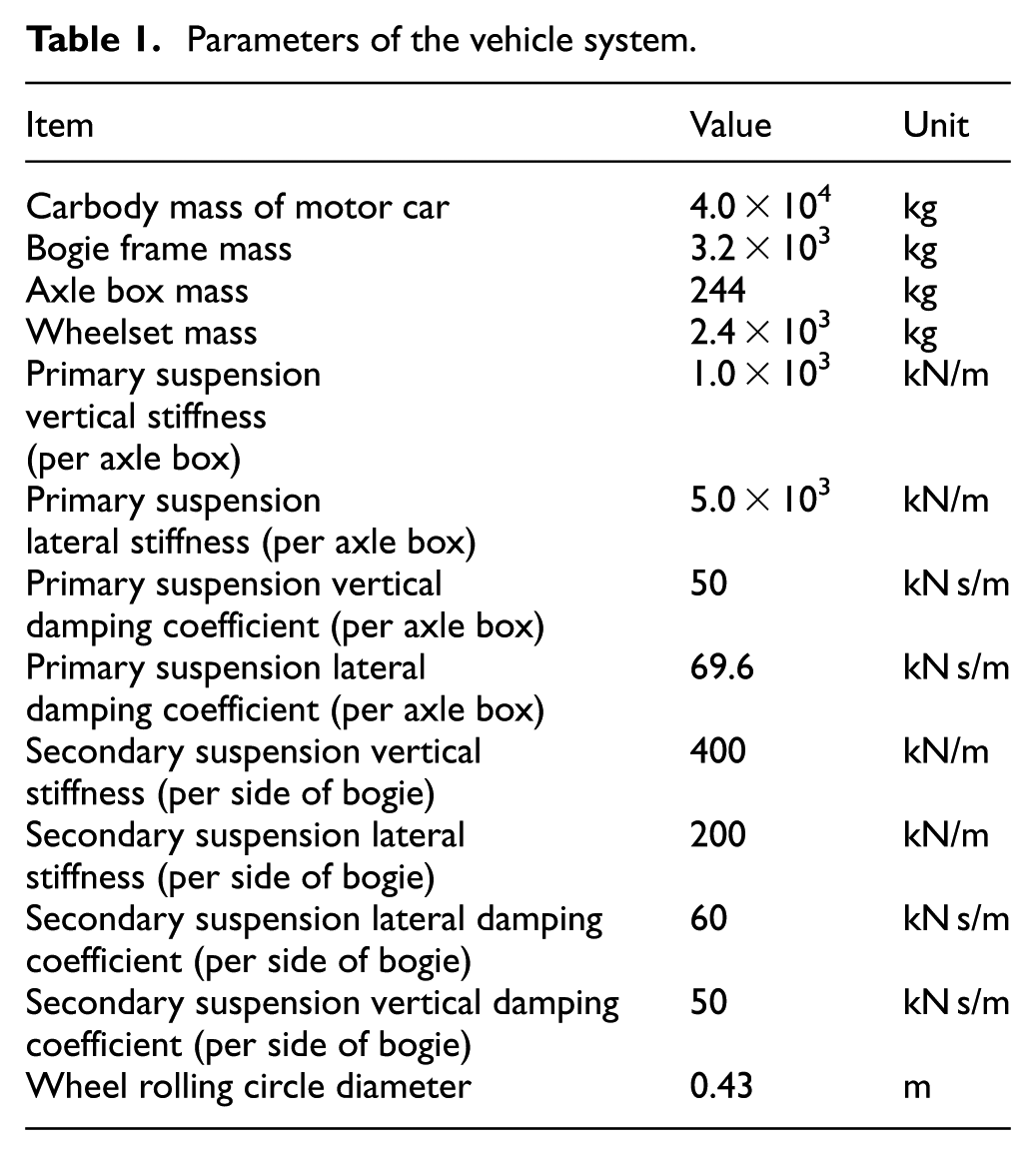
Taking a CHR380 train as an engineering example, the dynamics parameters of the vehicle system, track system, and axle box bearings are given, respectively, in Tables 1, 2, and 3, respectively.
Parameters of the vehicle system.
Parameters of the track system.

Parameters of the axle box bearing.

Numerical simulation of track irregularity
Ballastless track is widely used in China’s 300–350 km/h high-speed track. Therefore, in this article, we adopted the ballastless track spectrum as the sample input for track irregularity. To obtain the irregularity spectrum of the high-speed railways, the China Academy of Railway Sciences has performed detailed measurements on track irregularity of the main high-speed ballastless track using a track inspection train. The unified function of the track irregularity power spectral density (PSD) 19 is as follows

where the unit of S(f) is mm2/(1/m); f is the spatial frequency (1/m); and A and n are the fitting coefficients. The application scope of wavelengths is 2–200 m; the application scope of the vehicle speed is 300–350 km/h. According to the power spectrum of random track irregularity, the amplitude and phase of the spectrum are obtained by the periodogram method, and then the time-domain simulation sample of track irregularity is obtained by an inverse fast Fourier transform (IFFT).25,26 According to the numerical simulation method of a track spectrum, the track irregularity sample in the time domain is obtained at the speed of 350 km/h, as shown in Figure 4. For a vehicle–track coupled dynamics system with multiple DOFs and strong nonlinearity, the improved Newmark’s method27,28 was used to solve the problem efficiently and quickly.

Vertical track irregularity sample.
Vehicle wheelset experiment
The spatially coupled dynamics model was built by wheelset bearings’ contact nonlinear loads, which were determined by vertical, lateral, and overturning displacements of the vehicle component. The purpose of the vehicle wheelset experiment is to verify the effect of bearing contact forces on the wheelset vibration. By comparing the vibration response of the theoretical model with the experimental results, the accuracy of the wheelset–axle bearings coupled dynamics model is verified, which provides support for the vehicle/track dynamics model.
The wheelset experiment relied on systems from the CRRC Dalian Locomotive Research Institute Co., Ltd. Their experimental platform was used to simulate the actual running conditions of a high-speed vehicle wheelset. The dynamic response of the axle box was measured by modern measurement methods. The main equipment used are the following: (1) vehicle wheelset test system (CRRC Zhuzhou Institute Co., Ltd., Zhuzhou, China); (2) acceleration test system (BEETECH, Beijing, China), using three-axis acceleration nodes that can measure three-direction vibrational acceleration; and (3) displacement measurement system (Keyence Corp., Osaka, Japan).
The vehicle wheelset test system is depicted in Figure 5. The mechanical system consists of the wheelset, axle box bearings, and axle box. Vertical and transverse load excitation is applied to the bearing by the actuator, and the hydraulic station provides power for the actuator. The axle of wheelsets was under high-speed working, which is driven by the motor through the belt. As shown in Figure 5(c), a wireless acceleration node was mounted on the axle box, and the laser displacement sensor is fixed on the tripod. As shown in Figure 5(d) and (e), the laser point appeared on the axle box. The driving device is shown in Figure 5(b). The applied external excitation was composed of a vertical constant load and an axial alternating load, as illustrated in Figure 5(f).
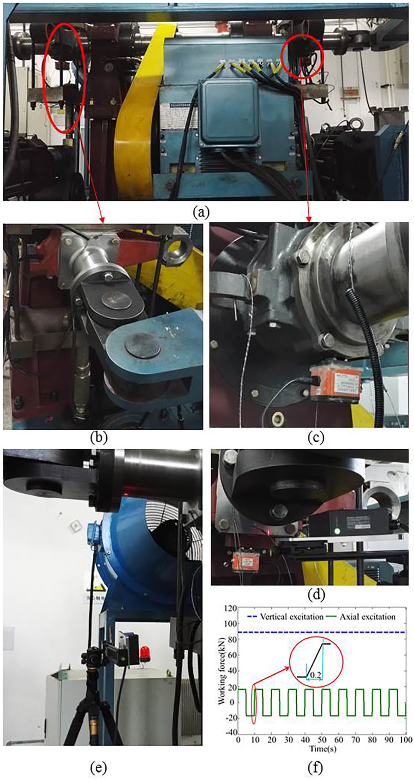
Vibration test system: photographs of (a) vibration test device, (b) loading mechanism, (c) acceleration testing device, (d) axial displacement testing device, (e) vertical displacement test device, and (f) graph of load excitation on axle box.
Results
Simulation results
Dynamic response of vehicle components
Under track irregularity excitation, considering the coupled characteristic of the axle box bearing, the acceleration response curves of the wheelset, axle box, bogie, and carbody are illustrated in Figure 6. Model_1 takes into account the dynamic model of the axle box bearing, while model_2 does not. The acceleration amplitudes of each component of model_1 are shown in Table 4.
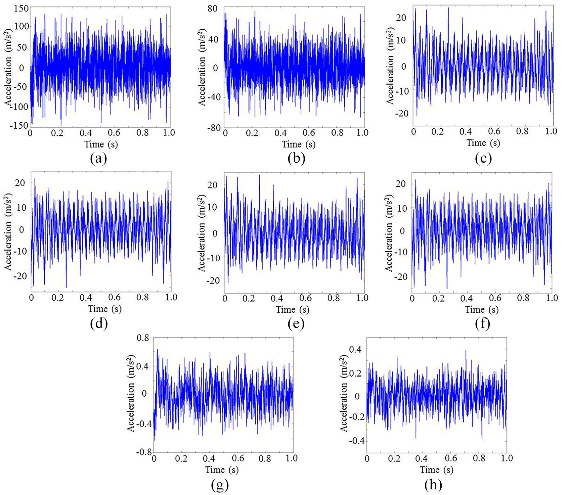
Response of vehicle–track coupled dynamics: (a) vertical acceleration of the wheelset, (b) lateral acceleration of the wheelset, (c) vertical acceleration of the axle box, (d) lateral acceleration of the axle box, (e) vertical acceleration of the bogie, (f) lateral acceleration of the bogie, (g) vertical acceleration of the carbody, and (h) lateral acceleration of the carbody.
Acceleration amplitudes of each component.

The contrast responses of the wheelset and axle box, which were calculated using model_1, are presented in Figure 7(a) and (b). The vertical and lateral acceleration amplitudes of the bogie were 18.7% and 23.3% higher than those of wheelset in model_1, respectively. Compared with the dynamic response of model_2, the contrast acceleration response of the carbody is presented in Figure 7(c) and (d). The vertical and lateral acceleration amplitudes of the carbody in model_1 are 7.6% and 5.3% higher than those of the carbody in model_2, respectively.
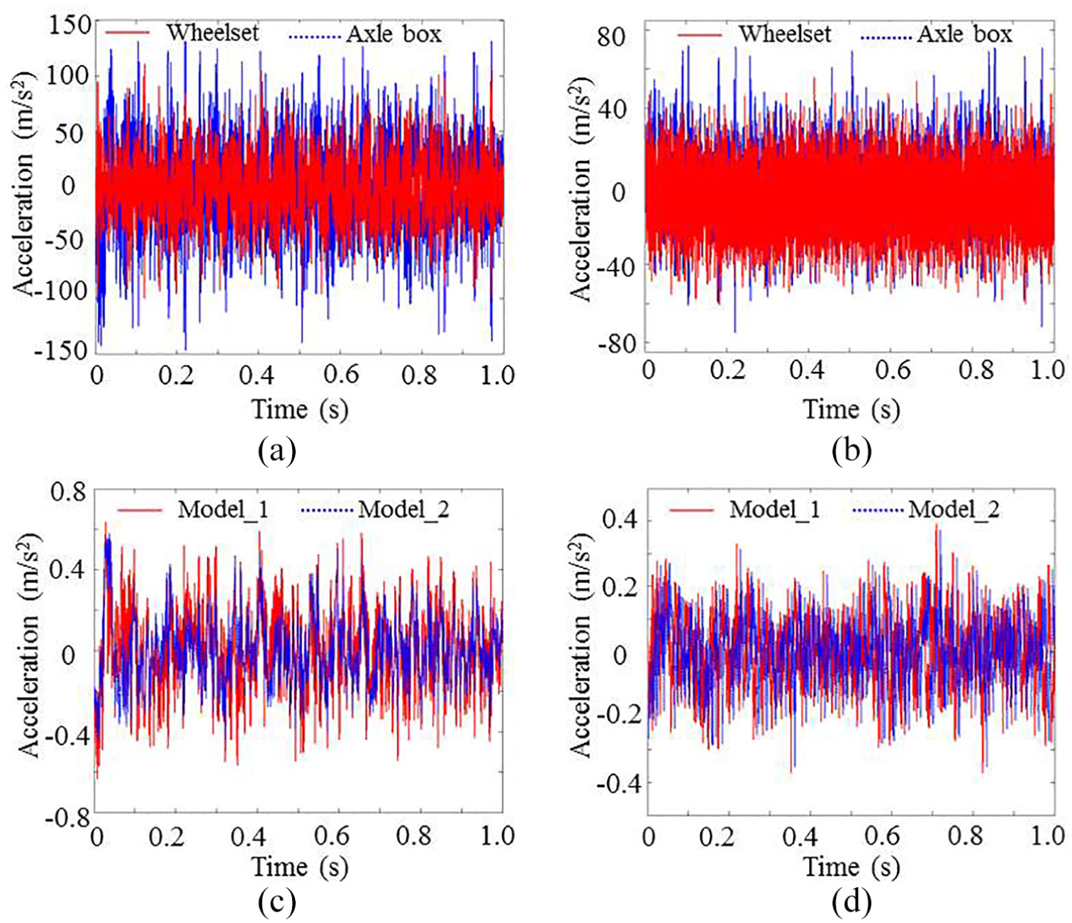
Comparative analysis of acceleration response: (a) vertical acceleration, (b) lateral acceleration, (c) vertical acceleration of carbody, and (d) lateral acceleration of carbody.
Load distribution of the axle box bearing
According to the vehicle spatially coupled dynamic model and the contact load model of axle box bearings, the time load history of axle box bearings on straight and curved tracks is presented in Figure 8. The maximum loads of the axle box bearing roller on the left and right columns were 23.3 and 26.6 kN, respectively, on the straight track. The maximum loads of the axle box bearing roller on the left and right columns were 35.0 and 30.0 kN, respectively, on the curved track. The load of bearing rollers was asymmetrically distributed, and the bearing area was mainly located in rollers 7–12.

Load distribution on rollers of axle box bearings: (a) left and (b) right bearings running on straight track; (c) left and (d) right bearings running on curved track.
Experimental results
Based on the measurements of the axle box vibrations recorded by the test system, the response curve of the axle box is plotted in Figure 9(a) and (b). Under experimental load excitation, the simulation results of axle box vibration are presented in Figure 9(c) and (d).

Vibration response of axle box: (a) displacement of axle box based on experiments, (b) acceleration of axle box based on experiments, (c) displacement of axle box based on simulation, and (d) acceleration of axle box based on simulation.
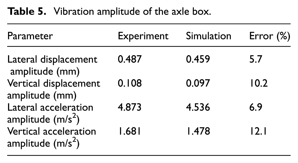
The lateral and vertical vibrations of the axle box change cyclically with variations in axial alternating excitation. As the axle load varies sharply, the vibration response changes severely. The vibration responses of simulation and experiment changed periodically, and the experimental results, simulation results, and errors for the axle box vibration response are shown in Table 5. The root mean square (RMS) of vibration response on the axle box is shown in Table 6.
Vibration amplitude of the axle box.
RMS of vibration response on the axle box.

RMS: root mean square.
Discussion
An axle box bearing is an important part of the vehicle transmission mechanism. The life and reliability of axle box bearings will directly influence vehicle operational reliability. Presently, the established wheel–track dynamics models ignore the spatially coupled relationship of a locomotive and cannot be used to obtain accurate dynamic mechanical characteristics of the bearings. In this article, based on vehicle–track coupled dynamics, we introduced the contact mechanical model of an axle box bearing coupled to the vehicle spatially vibrational displacement. In addition, the vehicle–track spatially coupled dynamics model was presented, considering the effect of track irregularity. Through wheelset experiments, the vehicle spatially coupled law and the validity of this theory model were verified.
Vehicle vibrations are weakened from the wheelset, axle box, and bogie to carbody, and the spatially coupled relationship of axle box bearings has less influence on the carbody vibration. As shown in Figure 6, the vibration of wheelsets was reduced through the primary spring suspension and secondary suspension. The vibration amplitudes of axle boxes, bogies, and carbodies were rapidly attenuated. The vibrations of axle boxes passing to bogies were attenuated to approximately 1/5 to 1/3. The vibration of bogies passing to carbodies was attenuated to 1/30, and the vibrations of bogies and carbodies were effectively restrained. Through theoretical analysis and field testing, the results proved that the suspension of a locomotive has excellent attenuation characteristics and is consistent with the research of Zhai et al.5,10 Presently, the traditional vehicle dynamics modeling1–5,29,30 ignores bearing coupled characteristics and simplifies the axle box and wheelset to a whole component. However, as illustrated in Figure 7(a) and (b), the vertical and lateral accelerations of the axle box were 18.7% and 23.3% higher than those of the wheelset, respectively; therefore, the vibration acceleration responses of a wheelset and an axle box differ greatly. As shown in Figure 7(c) and (d), the waveform and maximum value of vibrations on a carbody calculated by the coupled and traditional models were similar to those of lateral and vertical vibration accelerations, and the difference was very small (less than 5%). The main reason is that vehicle suspension systems suppress effectively the vibration from the track, so the vibration of the track structure weakens the vibration of the carbody above secondary suspension systems. Therefore, the traditional and coupled models can meet the requirements for the calculation and evaluation of vehicle running stability, and the traditional model has the advantages of simple and fast numerical calculation. However, to analyze the vibrational characteristics of the key structural components (wheelsets, axle box bearing) below the secondary spring suspension, it is necessary to use the spatially coupled model to more accurately reflect its vibration characteristics.
The mechanical characteristic analysis of the axle box bearings indicated that vehicle running routes have a significant impact on load distribution characteristics of the axle box bearing. As shown in Figure 8(c) and (d), bearing areas of rollers had an impact load on a bend, and the load increased dramatically. As shown in Table 5, the maximum load of the roller of the two row bearings increased by 50.2% and 12.8% on a curve, respectively, compared with the vehicle running on a straight-line section. The roller load increased sharply mainly due to wheel–rail load increases on a curve; in particular, the outboard wheel–track load increased rapidly, which induced a larger overturning moment. Zhai et al. presented simulations and experiments of the wheel–rail force on a small-radius curved track, and the results indicated that the wheel–rail force increased sharply in the running curve section. The load change law of axle box bearings in Figure 8 is consistent with the study of Zhai et al. 31 As shown in Figure 8(c), the maximum load of the axle box bearing roller was up to 35 kN, and the overturning moment caused by lateral load easily causes a partial load, which leads to stress concentration of the bearing rollers. This is very effective for improving the roller load distribution and increasing the contact fatigue life of bearings by modification design of the axle box bearing rollers. In addition, the time load process of bearing rollers can provide the boundary conditions for the modification design of axle box bearings and fatigue life calculation.
The spatially coupled relationships of axle box bearings have a distinct impact on dynamic vibration characteristics of a vehicle wheelset. The vehicle spatially coupled dynamics model presented in this article fully considers the nonlinear coupled relationship between the vehicle spatial vibration and the bearing load. As illustrated in Figure 9, the lateral and vertical vibrations of the axle box change cyclically with variations in lateral alternating excitation. As illustrated in Table 5, the axle box vertical amplitude aroused by lateral alternating load was approximately 0.108 mm, and it was approximately 22.2% of the lateral vibration. The experimental results show clearly that the lateral dynamic excitation has a significant impact on the axle box vertical vibration, owing to nonlinear bearing loads. Accordingly, it is essential that vehicle dynamics modeling needs to consider the nonlinear bearing loads and the spatially coupled relationship. As illustrated in Table 5, the errors between simulation and experiment for lateral displacement and acceleration were about 5.7% and 6.9%, respectively. The results of the experiment and simulation model are consistent, and the vibration response errors are reasonable, which verifies the accuracy of the vehicle wheel–track spatially coupled dynamics model. In addition, the RMS errors of displacement between the experiment and simulation are 5.4% and 12.8% as shown in Table 6, respectively. The RMS error of displacement is reasonable, but the RMS of vertical acceleration shows apparent discrepancies. As shown in Figure 9(d), the acceleration of axle box is decreased drastically under stable external incentives in the simulation model. However, the axle of wheelsets was under high-speed working, which is driven by the motor through the belt. So the vibration responses caused by the belt drive increase the test results. In addition, the environmental factors (motor, etc.) are not considered in the simulation model. So the acceleration RMS value of simulation is smaller than that from the experiments.
Conclusion
In this article, the vehicle wheelset coupled dynamics model was established, and the accuracy of the dynamics model was verified by vehicle wheelset experiments. The simulation and experimental results indicated that the isotropic vibration of axle box bearings has a complex and strongly spatially coupled relationship. The simulation and experimental results of the axle box displacement verify the accuracy of the dynamic model. The establishing method of the wheelset spatially coupled dynamics model provides a theoretical foundation for the vehicle–track dynamics model, which reflects the vehicle vibrational characteristics under track irregularity, and provides the theoretical basis for the structural and lubrication design of axle box bearings.
Footnotes
Handling Editor: Salvatore Strano
Authors’ Note
Jianghui Dong and Liping Wang are also affiliated with Department of Hand Surgery, Department of Plastic Reconstructive Surgery, Ningbo No.6 Hospital, Ningbo, China.
Declaration of conflicting interests
The author(s) declared no potential conflicts of interest with respect to the research, authorship, and/or publication of this article.
Funding
The author(s) disclosed receipt of the following financial support for the research, authorship, and/or publication of this article: This work was supported by the National Key R & D Program of China (No. 2018YFB1306701); National Natural Science Foundation of China (No. 51875076) and NSFC-Liaoning United Key Fund (No. U1708255).