
Abstract
This study investigates the effects of the use of two different types of recycled aggregates with known characteristics as backfill materials in newly built cantilever reinforced concrete retaining walls on the seismic performance of the walls. The physical properties of the recycled aggregates used as backfill materials were determined using aggregate tests. Subsequently, analytical studies for the reinforced concrete retaining walls containing recycled aggregates in the amounts of 25%, 50%, 75%, and 100% were performed under seismic and static loads and the results were compared with those obtained for the retaining walls containing 100% natural aggregate as the backfill material. The experimental and analytical studies showed that the internal friction angles and effective ground acceleration coefficients significantly affected the overturning moment and total active pressure values of the retaining walls. The results led to the conclusion that recycled aggregates can be partially or completely used as the backfill material in retaining walls. Moreover, the current conventional calculation methods for design and analysis were proven valid for the reinforced concrete retaining walls containing recycled aggregates as backfill materials.
Keywords
Introduction
Important issues such as the rate of technological developments, changing standards of living, changing habitats, environmental problems, traffic problems, and global warming put serious pressure on us to re-design our environment and social and physical conditions. The interconnectedness of these problems necessitates getting to the root of the problem and setting out to implement the necessary changes from this point onward. For these changes, developing new ways and methods for the immediate detection and resolution of the problems that cause environmental, economic, and social issues is necessary.
Considering the increasing number of ostentatious structures, renewed roads, restored dwellings, buildings demolished as part of urban transformation, and destructed buildings due to natural disasters, developing renewable and sustainable construction practices is needed. Within the scope of renewability and sustainability, as one of many perpetrators of environmental, economic, and social problems, an exhaustive investigation of the use of construction and demolition wastes (CDW) in the development of new construction practices is required because of their role in the environment. CDW negatively affect the soils, water resources, and air during the construction process and in the disposal sites. Moreover, their disposal in the environment causes environmental pollution and leads to environmental damage through heavy metals and hazardous substances they contain. In addition to their negative impacts on the environment, not using the waste materials results in an increase in the use of nearly extinct natural resources, energy requirement to process these resources, the requirement for labor and machine power, traffic problems, and carbon monoxide release into the environment. In many countries, the disposal of these wastes is achieved through their discharge to waste landfill sites. As the amount of the wastes increases, the need for the allocation and management of new landfill areas for the disposal of the wastes grows. However, these are high-cost procedures and the use of areas as landfill areas reduces the number of natural areas in the environment. Developed and developing countries encourage the reutilization of these wastes to resolve the problems stemming from CDW. The average Europe-wide reutilization of the CDW is around 46% and, according to the regulations of the European Parliament, their reutilization should reach at least 70% by 2020. 1 Thus, a vast amount of these wastes should be utilized.
Historical records reveal that the recycling and reuse of the CDW were not afterthoughts. The mortars produced from crushed bricks were used in the structures built during the Roman Empire (aqueducts, water channels, bridges, etc.). 2 During the Ottoman Empire, crushed brick and brick dust were added to the Khorasan mortar, which was frequently used in building constructions, to increase its resistance. 3 Today, there are a great number of detailed experimental and analytical studies investigating the reuse of the recycled aggregate in construction engineering applications. The majority of existing studies have focused on the chemical, physical, mechanical, and geometric properties of the recycled aggregates.2,4–11 In addition to the studies focusing on the material, to determine the behaviors of the recycled aggregates that are used as backfill materials and obtained from low-strength waste concrete under repeated loading, permanent deformation tests were performed12–16 and, to determine the shear strength, large-scale direct shear tests were performed.17–20 Moreover, in some studies, the performance of the recycled aggregate in lands was examined using lightweight dropping tests (LWDTs), plate loading tests, and other similar tests.21–24 Santos et al. 25 built a retaining wall reinforced with the geosynthetics made using recycled aggregates, monitored the wall during wet and dry seasons, and recorded the horizontal displacements. In general, studies have reported that the recycled aggregates could serve as alternatives to natural aggregate (NA) and their properties such as their water absorption capacities, unit weights, Los Angeles abrasion, specific bulk density, pH values, organic material contents, and chemical material contents were within the limits specified by relevant codes.
In light of the above-described reasons, a detailed experimental and analytical study was carried out to investigate whether the recycled aggregate obtained from low-strength waste concrete is usable as a backfill material in the cantilever reinforced concrete (RC) retaining walls under seismic and static loads. The characteristic properties of the two different types of recycled aggregates used within the scope of the study were determined using aggregate tests. Subsequently, analytical studies were performed for seismic and static loads to analyze the retaining walls in which two different types of recycled aggregates (in which approximately 25%, 50%, 75%, and 100% of the recycled aggregates were replaced by NAs as a backfill material) were used as the backfill materials and the results were compared with the analysis results obtained for the retaining wall containing only commonly used NA obtained from a quarry 26 as the backfill material. Through the review of the relevant literature and to the best of the knowledge of the authors, no studies were found focusing on the same subject. Therefore, the study is believed to lead the way for future studies on this subject.
Materials and methods
In the study in which two different types of recycled aggregates obtained from low-strength waste concrete were used as the backfill materials, the sliding and overturning analyses were conducted for nine cantilever RC retaining walls under seismic or static loads by following the conventional calculation methods. Of the eight retaining walls, four contained 25%, 50%, 75%, and 100% recycled concrete aggregate (RCA) as the backfill material, while the remaining four contained 25%, 50%, 75%, and 100% CDW in addition to the retaining wall containing 100% NA as the backfill material. The study, details of which are given in the following sections, aims to develop new ways and methods to reuse two different recycled aggregates as the backfill materials in the newly built retaining walls.
Material properties
The two different recycled aggregates (RCA and CDW) used as the backfill materials were produced from the recycling of the waste materials from two different buildings. These aggregates were obtained from minimum 10-year-old, classic RC structures with plain reinforcement (S220a) that were exposed to all environmental conditions and have a mean compressive strength of 14 MPa. Among the aggregates, the RCA contained only pure waste concrete, while the CDW contained a waste concrete mixture in addition to waste brick (10%) and trace amounts of glass pieces (0.1%). The waste concrete from which the RCA was obtained from a demolished building and the impurities in the concrete (plastic, iron, ceramic, brick, glass, etc.) were removed by hand. The impurities (plastic, iron, etc.) in the waste concrete obtained from another building and used to obtain CDW were also removed by hand, but the brick and trace amounts of glass in its content were left untouched. The acid extraction method was not used in the cleaning procedures for either of the aggregate sources. The waste concretes without impurities were transferred to the transformation site and, after the transformation process, RCA and CDW with the grain sizes of 0–5, 5–12, and 12–25 mm were obtained. After the transformation process, particle density (γs), bulk density (γn), water absorption capacity, and Los Angeles abrasion tests (based on the recommendations of the ASTM D 854-02, ASTM C 127-01, ASTM C 128-01, and ASTM C 131-03)27–30 were performed to determine the characteristics of the aggregates that will be used as the backfill material in the retaining walls (Table 1). The same tests were also performed for the NA used within the scope of the study and the results for all aggregate types are shown in Table 1. Table 1 shows the average density values of the materials obtained by mixing the aggregates with the grain sizes of 0–5, 5–12, and 12–25 mm to obtain suitable NA, RCA, and CDW for use as backfill materials.
Basic properties of NA, RCA, and CDW.
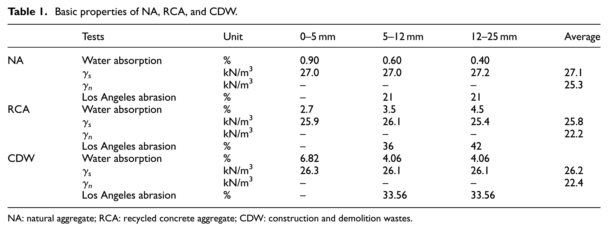
NA: natural aggregate; RCA: recycled concrete aggregate; CDW: construction and demolition wastes.
Specimens
Figure 1 shows the dimensions of the RC cantilever retaining walls containing recycled aggregate as the backfill material. In this study, nine retaining walls were analyzed. Table 2 shows the characteristics of both the retaining walls and the backfill materials behind the walls. Among the designations given to the cantilever retaining walls, NA indicates that the backfill material behind the retaining wall was NA; RCA indicates that the backfill material behind the retaining wall was the recycled aggregate obtained from pure waste concrete; CDW indicates that the aggregate obtained from the mixed waste concrete was used as the backfill material, while 25, 50, 75, and 100 indicate the percentages of the RCA and CDW in the backfill material mixture (Table 2).

Cross-section of cantilever RC retaining wall (dimensions in mm).
Characteristics of the RC retaining walls.

RC: reinforced concrete; NA: natural aggregate; RCA: recycled concrete aggregate; CDW: construction and demolition wastes.
For example, NA represents the RC cantilever retaining wall containing 100% NA as the backfill material. RCA75 represents the retaining wall containing RCA as the backfill material in the amount of 75% and CDW100 represents the retaining wall containing CDW as the backfill material in the amount of 100%. In the analytical studies for seismic and static loads, the bulk density (γ = γn) values of the backfill material mixture were used.
Calculations for RC retaining walls
In the design of the RC cantilever retaining walls, knowing in advance the damages that can occur during normal use and in which ways the walls can reach their bearing capacity under the most unfavorable conditions is of great importance. In the case of normal use (under static loads), retaining walls will clearly stay in balance with the force of gravity, soil stress, and external loads depending on the mass of the concrete wall. However, the dynamic effects emerging under seismic loads or occurring due to other causes and the changes in the soil will disturb the balance of the retaining walls and thus lead to permanent deformations both in the soil and in the wall. According to the widely accepted methods, the behavior of the RC cantilever retaining walls depends on the sum of the static lateral earth pressure under static loads and the dynamic lateral earth pressure under seismic loads. The earth pressure affecting RC retaining walls comprises two pressure components: active and passive pressures. Various experimental and analytical studies have been carried out to investigate the pressures occurring in retaining walls due to different ground motions. Coulomb 31 and Rankine 32 who conducted the first studies on the issue developed two different methods for the calculation of the earth pressures. The first studies that took the dynamic active and passive earth pressures stemming from the earthquake motion into account were conducted by Mononobe, 33 Okabe,34,35 and Mononobe and Matsuo. 36 The method known as the Mononobe–Okabe method was developed by these researchers and it considers the static effects occurring in the soil wedge behind the retaining walls due to earthquake motion together with the dynamic effects and regards the dynamic effects as an equivalent static load. The method is also known as the equivalent static pressure method and was developed based on the Coulomb sliding wedge theory.37–40 A great number of researchers have carried out experimental and analytical studies to verify the method.41,42 As a generally accepted method, the Mononobe–Okabe method is included in the earthquake codes of many countries, including Turkey. Furthermore, the Mononobe–Okabe method is even the first option to estimate lateral backfill pressures during earthquakes by structural engineers. Mononobe–Okabe solves the equations and suggests seismic active and passive lateral backfill pressures using a simple closed-form method. 43
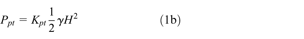
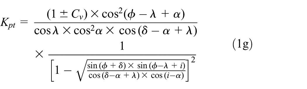
According to the Turkish Seismic Design Code 2007, 44 in the design of the retaining structures under seismic loads, both limit equilibrium (collapse) and service loads should be taken into account. According to the code, retaining structures can be designed to allow a displacement at a degree that will not disrupt their functions after an earthquake. Moreover, the code adopts the equivalent static method approach in the calculation of the earth pressures affecting the retaining walls due to earthquake. According to the method, total active earth pressure (Pat) under seismic loads is calculated by equation (1). Here, I represents the structure importance factor, A0 represents the effective ground acceleration, α represents the vertical angle of the back surface of the retaining wall, H represents the wall height, q represents the additional loading (surcharge), ϕ represents the internal friction angle of the soil, δ represents the friction angle between the soil and wall, i represents the horizontal angle of the soil surface, γ (γn) represents the bulk density, Ch and Cv represent the horizontal and vertical acceleration coefficients, respectively, λ represents the equivalent seismic coefficient, Kat represents the total active earth pressure coefficient, and Kpt represents the total passive earth pressure coefficient


The seismic dynamic active pressure coefficient, Kad, and dynamic passive pressure coefficient, Kpd, are calculated by equation (2)


The static active pressure coefficient, Kas, and static passive pressure coefficient, Kps, in equation (2) are obtained by taking λ = 0 and Cv = 0. Equation (3) describes the changes in the additional dynamic active and passive earth pressures throughout the soil height occurring due to the soil mass under seismic loads


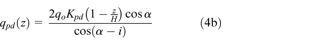
Equation (4) describes the changes in the active and passive earth pressures throughout the soil height due to the uniformly distributed loadings under seismic loads in addition to the static earth pressure

In the special case of uniform soil properties, when Z = H/3, the components of the active (positive) and passive (negative) earth pressures generated due to the earthquake, Qad and Qpd, are calculated by equation (5). Moreover, with Gp representing the weight of a free cantilever, the inertia force (Ppd) due to the weight of the free cantilever is calculated by equation (5c)


In light of the above elaborated information, the analytical calculations will be performed by taking the loads shown in Figure 2 into consideration. According to the Turkish Seismic Design Code 2007, 44 in the seismic calculations of the cantilever retaining structures, safety factor against sliding should be at least 1.1 and the safety factor against overturning should be at least 1.3.

Static (A, B) and dynamic (C–E) loads are taken into account in the retaining walls.
Analytical studies
Figure 1 shows the dimensions of the RC cantilever retaining wall discussed in the study. According to Requirements for Design and Construction of Reinforced Concrete Structures code, 45 the C30-class concrete and S420a-type reinforcement were selected for the concrete and reinforcement in the retaining walls, respectively. The weight per unit volume of the RC was taken as γc = 25 kN/m3. According to the soil properties of the area where the retaining walls were built, the soil was classified in the B class and had a strength of σzs = 200 kN/m2. Within the scope of the study, two different analytical studies were carried out for the retaining walls.
In the first analytical study, I, α, δ, and i were taken as 1, 3.18, 0, and 0, respectively, and the effective ground acceleration of the region in which the wall was built and that was classified as the first-degree seismic zone was taken as A0 = 0.4; then, separate analyses were carried out for the internal friction angles (ϕ) of 40°, 45°, 50°, 55°, and 60°.
In the second analytical study, I, α, δ, i, and ϕ were taken as 1, 3.18, 0, 0, and 40°, 50°, and 60°, respectively, and the changes in the dynamic total active pressure and dynamic overturning moment values of the retaining walls built in different seismic zones (IV, III, II, I) with effective ground acceleration coefficients of (A0) 0.1, 0.2, 0.3, and 0.4 44 were investigated in detail. The positive effect of passive pressure was not taken into account in both analyses.
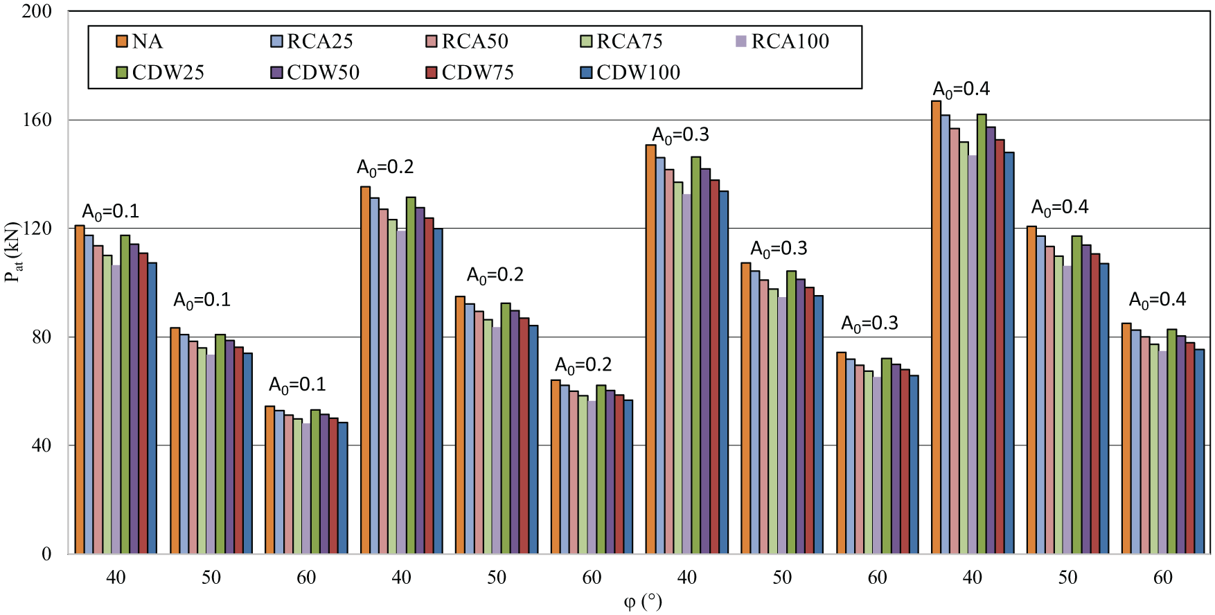
Figures 3 and 4 show the results obtained in the first analytical study performed for the RC cantilever retaining walls by taking the mentioned parameters into consideration. As shown in the figures, the overturning moment (M) values and total active pressure (Pat) values of all walls under both conditions (seismic and static loads) decreased with the increasing internal friction angle of the backfill materials.

Overturning moment–internal friction angle of backfill relationships: (a) static and (b) dynamic.

Total active force–internal friction angle of backfill relationships: (a) static and (b) dynamic.
Under seismic or static loads, the M and Pat values of the retaining walls containing NA, RCA, and CDW as the backfill materials were decreased by about 56% when the internal friction angle was increased from 40° to 60°. The decreases in the overturning moment and Pat values were attributed to the increase in the shear stress of the backfill material soil with an increased internal friction angle. Because, when the internal friction angle of the backfill material increases, the shear stress and rigidity of the backfill material increase, the total active earth pressure coefficient (Kat) decreases. Therefore, the overturning moment and Pat values decreased with the increase of the internal friction angle. The difference (3%) between both the M and Pat values of the RCA-containing and CDW-containing specimens (e.g. RCA100 and CDW100) with the same internal friction angle (e.g. 40°) under seismic or static loads was negligible and the difference was due to the difference between the bulk density values of the backfill materials.
Nevertheless, as the amount of the aggregate used as the backfill material in the specimens from the same series (e.g. RCA25, RCA50, RCA75, RCA100 or CDW25, CDW50, CDW75, CDW100) with the same internal friction angle (e.g. 40°) increased, the M and Pat values of the walls under seismic or static loads decreased at a negligible level (1%). Similar results were also obtained for the other internal friction angles (45°, 50°, 55°, 60°). The internal friction angles of the NAs and recycled aggregates may differ depending on the differences in their characteristic properties. Sivakumar et al. 17 reported that the difference between the internal friction angles of the NAs and recycle aggregates was approximately 5°. From the studies found in the literature, the internal friction angle of the recycled aggregates was determined to be 45° using large-scale direct shear tests.17,20,25 Thus, when the internal friction angle of the recycled aggregate was accepted to be 45° and the internal friction angle of the NA was accepted to be 50°, compared with the NA-containing walls, the moment and Pat values of the recycled aggregate–containing walls were increased by 12% under seismic loads and by 17% under static loads. Although the increases in the overturning moment and Pat values are not believed to be at a level that necessitates refraining from the use of recycled aggregates as the backfill materials, it nevertheless should be of concern in the design of RC retaining walls. The results revealed that the partial (25%, 50%, 75%) or complete (100%) use of recycled aggregates (RCA or CDW) as the backfill materials in the retaining walls did not negatively affect the seismic indicators of the walls. Thus, the structural behaviors of the RCA- or CDW-containing RC cantilever retaining walls under seismic and static loads were similar to those of the NA-containing retaining wall.
The results obtained in the second analytical study are shown in Figures 5–8. As shown in the figures, as the effective ground acceleration coefficients of the seismic zones in which the retaining walls were built increased, the M and Pat values of all walls increased for all internal friction angles (40°, 50°, 60°) under seismic loads.
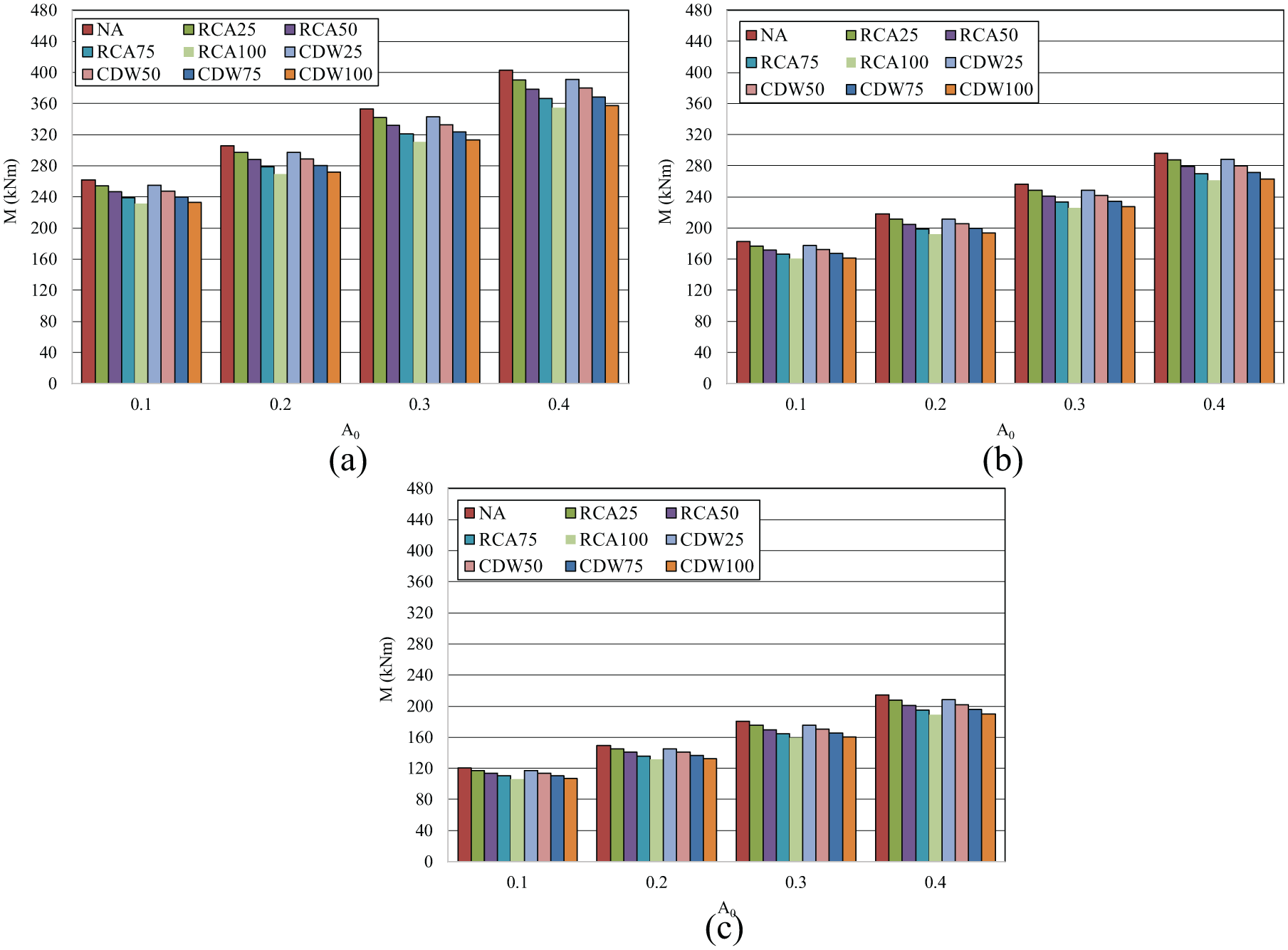
Overturning moment–effective ground acceleration coefficient relationships: (a) ϕ = 40°, (b) ϕ = 50°, and (c) ϕ = 60°.

Total dynamic active force–effective ground acceleration coefficient relationships: (a) ϕ = 40°, (b) ϕ = 50°, and (c) ϕ = 60°.

Overall evaluation of the overturning moment–internal friction angle of backfill relationship.
Overall evaluation of the total dynamic active force–internal friction angle of backfill relationship.
The increase in the M and Pat values under seismic loads is a usual consequence of the increase in the acceleration values of the grounds. As revealed by Figures 5 –8 in the walls with the same effective ground acceleration but different internal friction angles, the walls with a smaller internal friction angle (40°) had greater M and Pat values than those of the retaining walls with a higher internal friction angle. The difference in both the M and Pat values of the RCA- or CDW-containing specimens (e.g. RCA25 and CDW25) with the same effective ground acceleration coefficient and internal friction angle (e.g. 0.1 and 40°, respectively) was negligible (2%) and the difference was attributed to the difference between the bulk density values of the backfill materials (Figure 2). Furthermore, under seismic loads, as the amount of the aggregate used as the backfill material in the specimens from the same series (e.g. RCA25, RCA50, RCA75, RCA100 or CDW25, CDW50, CDW75, CDW100) and with the same effective ground acceleration coefficient and internal friction angle (e.g. 0.4 and 60°, respectively) increased, the difference between the M and Pat values of the walls decreased at a negligible rate (1%). Similar results were also obtained for the other internal friction angles (40°) and effective ground acceleration values (0.1, 0.2, and 0.3). The results showed that the partial or complete use of the recycled aggregates as backfill materials in the retaining walls built in different seismic zones did not have any negative effect on the seismic indicators of the retaining walls. Hence, the results led to the conclusion that the use of the RC cantilever retaining walls containing RCA and CDW as the backfill materials was suitable for all seismic zones.
Conclusion
The study investigates the effects of the use of two different types of recycled aggregates obtained from CDW as the backfill materials in RC cantilever retaining walls on the seismic performance of the walls. The ratio of the recycled aggregate in the backfill material, the internal friction angle of the backfill material, and the effective ground acceleration coefficient were selected as the parameters in this study. The results obtained for these parameters are listed below.
The partial or complete use of the recycled aggregates as the backfill material in the retaining walls did not negatively affect the seismic indicators of the walls.
Under seismic and static loads, the structural behaviors of the retaining walls in which the recycled aggregates were used as the backfill material were similar to those of the retaining wall containing NA as the backfill material and have the same internal friction angle as the recycled aggregate–containing retaining walls.
Among the calculations made for both seismic and static loads, the current conventional calculation methods were determined to be also valid for the walls containing recycled aggregate as the backfill material.
The overturning moment and total active pressure values of all retaining walls under seismic and static loads decreased with the increasing internal friction angle of the backfill material behind the retaining walls. The analysis showed that internal friction angle was the most influential parameter and although the 5° difference between the internal friction angles of the recycled aggregate and NA (450–500) affected the characteristics of the walls under seismic and static loads, the effect of the difference did not reach a level that necessitates refraining from the use of the recycled aggregate. However, this difference should be taken into account in the design of RC retaining walls.
As the effective ground acceleration coefficients of the seismic zones in which the retaining walls were built increased, the overturning moment and total active pressure values of all walls under seismic loads increased.
There were negligible differences between the overturning moment values and total active pressure values of the recycled aggregate specimens with the same effective ground acceleration coefficients and internal friction angles under seismic loads and the differences were attributed to the different bulk density values of the backfill materials.
The results showed that the partial or complete use of the recycled aggregates that were built in different seismic zones and had different characteristics as the backfill materials in retaining walls did not have any negative effect on the seismic indicators of the walls. Hence, the RC cantilever retaining walls containing RCA or CDW as the backfill material were deemed suitable for use in all seismic zones.
Although the results of these studies highlight the viability of using RCA or CDW sourced from low-strength concrete waste as the backfill material in RC cantilever retaining walls, further research is necessary to validate this conclusion in a more general sense.
Footnotes
Handling Editor: George Wardeh
Declaration of conflicting interests
The author(s) declared no potential conflicts of interest with respect to the research, authorship, and/or publication of this article.
Funding
The author(s) received no financial support for the research, authorship, and/or publication of this article.