
Abstract
This article studies the dynamics of oilwell drillstring under large and small axial impact loads. For the case of large impact load, the drillstring is regarded as a continuous bar under the impact load of a falling mass, and the energy conservation method is implemented. A sensitivity analysis is conducted to investigate the effect of cross-sectional area of the drill string on the impact stress. Results show that the design of drillstring with different cross-sectional areas is not a suitable method. In order to understand the effect of high-frequency small axial impact (applied from percussion tools or downhole generators) on the drillstring vibration, a mechanical model in which the drillstring is regarded as a 2-degree-of-freedom system under a harmonic force is developed. Sensitivity analysis on the effects of impact generator placement and impact frequency on drillstring dynamics are conducted. Results show that the impact generator should be installed near the drill bit and that high frequency is recommended to be used.
Introduction
For the exploration of oil and gas, wells are drilled with a rotary drilling system. Drillstring is regarded as the medium of transporting the energy from surface to drill bit. The drillstring is subjected to various types of loads during the drilling process. 1 As a result, the problems related to drillstring dynamics are fairly complex. Many phenomena such as parametric resonance, whirling, stick-slip vibration, and contact with the borehole wall may be incoled.2–4 The drillstring dynamics plays significant role in many aspects such as the rate of penetration (ROP), bit life, and cost of maintenance. 5 As a result, it is of great significance to understand the drillstring dynamics so as to reach a best drilling efficiency.
During the drilling process, vibrations are generated due to interaction between drill bit and rock formation. To date, a large number of models have been established to investigate the axial vibration of drillstring in coupled or uncoupled manners.6,7 An early research was presented by Bailey and Finnie, 8 in which partial differential equation of a longitudinal bar was used to describe the axial vibration of the drillstring. Mathematical model of axial vibration of drillstring excited by both force and displacement were studied by Li and Guo. 9 By using static models, Aadnoy et al. 10 investigated the interaction between drillstring and wellbore during the tripping process. Wada et al. 11 studied the mechanism for high-frequency axial vibration of ultra-long drillstring during offshore drilling.
The dynamics of a body undergoing impact load appear in many engineering problems. 12 For a drilling process, vibration and impact are usually unwelcome, but some impact loads may be unexpected, for example, impact due to drilling accident. 13 It is well known that the impact loads usually lead to large impact stress and further failure of equipment. 14 Impact loads are an important cause for failure of drillstring components, and failure of a drilling operation as a result of tool failure due to impact load is time consuming and can be extremely costly. 15 In fact, however, introducing impact loads into a drillstring has the possibility to mitigate vibration or advance the drilling efficiency, for example, the use of impact generator. 16
Few researches on the subject of drillstring under impact load have been conducted. Skeem et al. 17 developed an analytical model based on plane wave propagation through a distributed mass representation of the drillstring. Kalsi et al. 18 used the finite element method to predict the dynamic response of a drillstring subjected to jarring. Yigit and Christoforou 19 modeled the drillstring as a slender beam with a simply supported lower part to study the transverse vibrations of drillstrings caused by axial loading and impact with the wellbore wall.
Impact load was taken into account in studying the dynamics of drillstring, yet the reported studies have either addressed the dynamic response only, or presented the actual phenomena. The influences of drillstring structure and impact parameters have not been considered within the studies of drillstring dynamics. Whether or not all kinds of impact load are detrimental to the drillstring is an unanswered question, and vibration utilization is rare in studying the drillstring dynamics. In fact, the impact may be used to improve drilling efficiency.20,21 For the purpose of gaining an improved understanding of the axial impact loads on the drillstring dynamics, investigations based on simplified models are conducted by studying the axial vibration behavior of the drillstring under large and small axial impact loads.
Effects of large axial impact on drillstring dynamics
Deformation and impact stress generate when a body is subject to large axial impact load. Usually, the time duration of impact load is very small, which makes different parts of the body reach the same stress at different times. Once the stress wave is formed, it propagates in the system, which results in vibration of the system. It is difficult or may be expensive to measure the impact force, stress, and deformation of a complex system, since they change over time.
Investigation of nonlinear vibration of string with large amplitudes has been conducted by Omran et al. 22 In engineering application, however, the maximum stress and deformation are usually considered only rather than their change rule. In this section, energy conservation method is used to analyze the drillstring dynamics. As a prelude to the theoretical analysis, a model of the drillstring which undergoes an axial impulse excitation (Figure 1) is presented. The impact is considered as an instantaneous process on a slow timescale. To simplify the problem, the deformation of the drillstring is treated as a linear spring-type deformation. The axial impulse excitation problem is transformed into a problem of a block hitting the drillstring. Here, three assumptions are made: (1) the collision between the block and the drillstring is plastic collision, which means rebound of the block is neglected; (2) the energy dissipation is neglected and all energy of the block is transformed into elastic strain energy of the drillstring; and (3) the influence of inertia effect of structure and strain rate effect of material are not taken into account.

Idealization of the mechanical system.
In the model, W and k are used to denote the weight of block and the stiffness of drillstring, respectively. The block impacts on the drillstring with velocity v. It is assumed that the velocity of the block reduces to zero after contacting with the drillstring. Here, a dynamic impact factor K by the following equation is defined
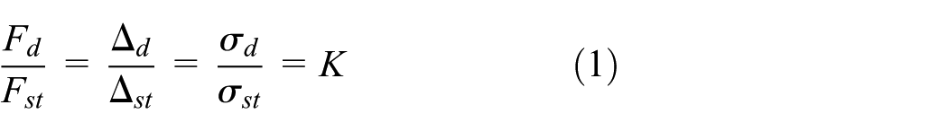
where
Once the velocity of block decelerate to zero, both the contact force and deformation reach their maximum value

Finally, the dynamic impact factor can be given as
From equation (3), it is easily seen that at large values of
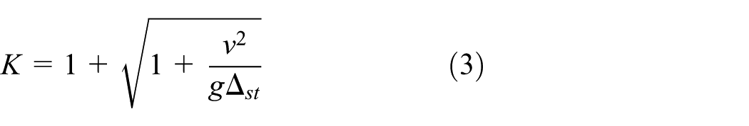
In order to obtain the effect of axial impact load on drillstring design, three simplified drillstring models are presented. Figure 2 shows three different drillstring structures, on which a block with weight W is impacting at velocity v. Both A1 and A2 represent the cross-sectional area of the pipes.
Simplified model for the drillstring: (a) structure with different cross-section areas, (b) structure with uniform area A1 and (c) structure with uniform area A2.
For the convenience of expression, Cases A, B and C are used to represent the cases corresponding to Figure 2(a)–(c). For cases A and B, the impact stress

and for Case C

where

where a is the section length of which the cross-sectional area are equal to A1, and there is a = l in Case B and a = 0 in Case C.
For the three cases, the drillstring with length 1000 m is studied. The weight and impact velocity of the block is assumed to be 100,000 N and 10 m/s, respectively. The drillstring is analyzed, in which Young’s modulus assumes value of 210 GPa and a = 10 m. In the following section, case studies are conducted to show the maximum stress for different structures. For the case studies, the sizes of drill pipe and drill collars are referred to an actual drilling (well number: Tazhong 62-5H) in the Tarim Oilfield of China.
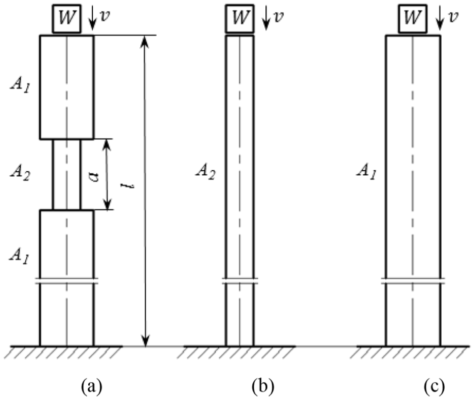
The results of the three cases are shown in Tables 1 and 2. Case A represents the drillstring with different cross-section pipes, and Cases B and C represent the cases with uniform areas A1 and A2, respectively. As can be seen from Table 1, for the three cases, the increase of cross-sectional area leads to a decrease of deformation and increase of dynamic impact factor of the drillstring. For case A, the impact stress is relative high due to the high dynamic impact factor and small value of A2. For case B, the impact stress is much less than Case A due to a lower dynamic impact factor. And for Case C, the impact stress is the lowest because of a relative large cross-sectional area.
Dynamical responses of the drillstring for three different structures.
For Table 1, the structural parameters related to Figure 2(a)–(c) are: A2 = 0.0034 m2 (5 in drill pipe with its size of 127 × 108.6 mm), A1 = 0.0191 m2 (6.75 in drill collar with its size of 171.4 × 71.4 mm).
Dynamical responses of the drillstring for another three different structures.

For Table 2, the structural parameters related to Figure 2(a)–(c) are: A2 = 0.0191 m2 (6.75 in drill collar with its size of 171.4 × 71.4 mm), A1 = 0.0284 m2 (8 in drill collar with its size of 203.2 × 71.4 mm).
With increasing the cross-sectional area, the stiffness of drillstirng increases, and the static deformation decreases, resulting in an increase in dynamic impact factor. Since the drillstring works in a hostile environment, a small increase in the dynamic stress may lead to failure of the drilling tool. It is evident that the impact stress is related to the magnitude of the impact load, drillstring structure, and stiffness. Results indicate that uniform drillstring with large cross-sectional area is recommended to be used. The cost, however, will increase sharply with the increase of cross-sectional area of the drillstring. In addition, the hook load will increase, which asks for large-scale derrick, leading to further increase in the cost. As can be seen from this analysis, the drillstring is not suitable to be designed with pipes of different cross-sectional area, which can be useful and helpful for the designing of downhole tools. In addition, the major measure to improve the impact resistance is to reduce the stiffness of the drillstring. Hence, components which may reduce the stiffness of the drillstring, shock absorber for example, are recommended to be used in the design of drilling assembly.
Effects of small axial impact on drillstring dynamics
Mathematical modeling
Impact excitation is usually thought to be harmful to the drilling efficiency. However, many engineering applications have shown that the high-frequency small axial impact has the potential of improving the longevity and dull condition of the bit and thus improving the drilling efficiency.23–25 Results show that the high-frequency small axial impacts generated by an impact generator enhance smoothness of the drilling by providing subsidiary energy for rock crushing. But how will the impact generator affect drillstring vibration and what should be done about it have been rarely reported. In this section, the effect of high-frequency small axial impact on drillstring vibration is to be studied.
As a prelude to the study, a simplified pendulum model characterized by 2 degree of freedom (DOF) is developed (as presented in Figure 3). In this analysis, emphasis is placed on the drillstring vibration. The bit keeps inserting into the rock due to weight on bit and impact load, so the bit–rock interaction is modeled as rigid a wall. The drillstring is assumed to be a straight hollow beam that consists of drill pipes and drill collars. The drillstring is composed of drill pipes with length of 2850 m and drill collars with length of 150 m. Hence, the impact generator may be installed in the drill pipe section or the drill collar section. The two masses refer to the two DOFs are the part above the impact generator M1 and the part below the impact generator M2, where M represents the mass. It is shown by Fourier that any periodic motion can be presented by a series of sines and cosines that are harmonically related. In this work, the impact generator is contained by M2, and the excitations act on this mass in the form of harmonic axial force

System to be researched: (a) general view of the drillstring and (b) simplified model of the system.
The equation of motion of the drillstring is

where
Magnitudes of displacements of the two parts can be expressed as 26

where A and B are expressed as


From the model formulation and corresponding solutions, it can be found that amplitudes of the two parts are functions of the impact frequency, masses, and stiffness of the parts. During the drilling applications, the main concern is the displacements of the drillstring. In addition, it is anticipated that the vibration of the bottom-hole assembly (BHA) can be suppressed so that energy from the rotary table can be used as much as possible to crush the rock. As a result, it is important to know the effects of impact frequency and impact generator placement on the axial drillstring vibration.
In the next two sections, sensitivity analysis of the impact frequency and impact generator placement will be conducted through cases studies. For this analysis, external diameters of the drill pipes and drill collars are 0.127 and 0.159 m, respectively. And internal diameters of the drill pipes and drill collars are 0.108 and 0.072 m, respectively. Density and modulus of elasticity of the drillstring are ρ = 7850 kg/m3 and E = 210 GPa, respectively. The damping coefficient of the system is 5000 N s/m and impact force amplitude

where A is the cross-sectional area of the drillstring. For the section that drill pipes and drill collars are involved, the stiffness is calculated by treating it as two springs connected in series.
Effects of the impact generator placement on drillstring vibration
Since the two parts are separated by the impact generator, lengths of the two parts are related to the impact generator placement. As can be seen from the analysis in the previous section, it is obvious that the impact generator plays a significant role in the drillstring vibration. In this section, influence of the impact generator placement on drillstring vibration will be analyzed.
In the drilling applications, energy is imparted into the rock to the point of the rock failure and removal. Rock failure depends on the physical properties and environmental properties of the rock and loads that act on the rock. Based on the operational characteristics of some percussive tools,27,28 it is believed that the high-frequency small axial impact improves the drilling efficiency by accelerating the rock failure process. Varying the regularity of rock failure may be one of the explanations that the high-frequency small axial impact improves the ROP in the drilling practices. Since the impact generator is to provide subsidiary energy to the drill bit for rock crushing, it is not appropriate to install the impact generator far away from the drill bit. In this way, different values of l2 ranging from 10 to 200 m are analyzed.
During the drilling, displacement D2 is anticipated to be the less the better. When at anti-resonance frequency of the system, the system acts as a vibration absorber and reduces the motion of the certain parts. The anti-resonance frequency of the system can be given as

which is also the resonance frequency of the mass M1. In this section, impact frequency is selected to be 0.16 rad/s, corresponding to the anti-resonance frequency 29 of the system for the situation that the impact generator is close to the bit (l2 = 10 m).
Figures 4 and 5 illustrate amplitudes of the two parts D1 and D2 under different impact frequencies. As can be seen from the two figures, D2 is much less than D1. This is because the impact generator acts as a damper, which mitigates the vibration of M2. Trends of the two curves show that the amplitudes of the two parts increase with increasing l2, which means that decreasing the distance between the impact generator and drill bit is beneficial to mitigate vibration of the drillstring. Consequently, the impact generator is recommended to be installed close to the drill bit, which is in agreement with the field test results.

Relationship between the displacement magnitude of the mass above the impact generator D1 and the length below the impact generator l2 (with

Relationship between the displacement magnitude of the mass below the impact generator D2 and the length below the impact generator l2 (with
Effect of the impact frequency on drillstring vibration
As can be seen from the analysis in section “Mathematical modeling,” impact frequency plays a significant role in the drillstring vibration. In this section, influence of the impact frequency on drillstring vibration is studied through analyzing the conditions l1 = 2990 and l2 = 10 m (close to the length of a single drill pipe or drill collar), which is based on the results of section “Effects of the impact generator placement on drillstring vibration” (the impact generator is placed at a position near the drill bit). Results of the case are shown in Figures 6 and 7, where the impact frequency ranges from 0.1 to 120.

Relationship between the displacement magnitude of the mass above the impact generator D1 and impact frequency

Relationship between the displacement magnitude of the mass below the impact generator D2 and impact frequency
Figure 6 shows the relationship between the vibration amplitude D1 and the impact frequency, where the plot is displayed in log scale along the x-axis. As depicted in the figure, D1 reaches its maximum at the frequency of 0.16 rad/s, corresponding to the resonance frequency of the part M1, which is also the anti-resonance frequency of the system. After reaching its maximum, amplitude of the part M1 decreases quickly to a value close to zero. Figure 7 presents the relationship between amplitude D2 and impact frequency. From Figure 7, it is observed that D2 first increases and then decreases with an increase in the impact frequency. D2 reaches its maximum at the frequency of 51.7 rad/s, corresponding to the resonance frequency of the part M2. For a structure with small damping coefficient, the responses can be 10 or more times higher than normal if resonance is achieved. 30 Hence, the resonance should be prevented in engineering practice. For this case, a frequency close to 51.7 rad/s is recommended to be avoided.
Since the impact generator is used to provide subsidiary energy to accelerate rock crushing, from the perspective of increasing ROP, a low frequency is not appropriate. From the results of Figures 6 and 7, it is concluded that vibration induced by the excitations is weak at a high frequency (large than 80 rad/s). In fact, high frequencies larger than 80 rad/s (about 12.7 Hz) are commonly used in the drilling applications. 31 Results in this section promise a great agreement with the field applications. It is easy for many engineers to think that the high-frequency axial impact may be a source of vibration and severe limitation for the drilling tools. The analysis in this section can be an explanation for this question. For a high-frequency excitation, the drillstring vibration induced by the excitation can be negligible. Consequently, from the perspective of both rock crushing and drillstring vibration, it is suggested that a high frequency is to be used. Of course, the impact frequency is limited by the ability of equipment wherein the excitations are generated.
Conclusion
The drillstring dynamics plays significant role in many aspects such as the ROP, bit life, and cost of maintenance. In the drilling operations, impact loads are common for the drillstring. In this work, dynamic analysis of the drillstring has been carried out for axial impact load. The work includes two parts: effects of large and small axial impact loads on the drillstring dynamics.
For the case of large axial impact load, the drillstring is modeled as a linear spring and the axial impulse excitation problem is transformed into a problem of a block hitting the drillstring to study the deformation and impact stress of the drillstring. The deformation and stress of the drillstring component are calculated using Engineering Mechanics, and the dynamic impact factor is used in analyzing the drillstring dynamics. The dynamic impact factor helps in understanding the results of the impact load. The dynamic problem is analyzed using energy method. Initially, the system model is analyzed qualitatively by using the principle of conservation of energy and then the results are verified by analyzing three cases. Results show that the impact stress is related to magnitude of the impact load, size of the component and stiffness of the component. Thus, the drillstring is not suitable to be designed with pipes of different cross-sectional area, and components that may reduce the stiffness of the drillstring are recommended to be used in drilling assembly design.
In order to study the effect of small axial impact load on drillstring dynamics, a simplified pendulum model of the drillstring characterized by two DOFs is first developed. The two DOFs refer to the part above the impact generator and the part below the generator. Mathematical analysis of the system is conducted and dynamic responses of the two parts are obtained. Influences of the impact generator placement and impact frequency on drillstring vibration are investigated through case studies, wherein the drillstring consists of drill pipes with length of 2850 m and drill collars with length of 150 m. For the impact generator placement, results show that amplitudes of the two parts increase with increasing the distance between the impact generator and drill bit, which means that the impact generator should be installed close to the drill bit. For the impact frequency, results show that D1 reaches its maximum at the anti-resonance frequency and D2 at the resonance frequency of the system. The impact generator is recommended to be used with a high-frequency excitation. For a high-frequency excitation, drillstring vibration that is induced by the excitation can be negligible. What should be addressed is that this analysis focuses on only one mode of the drillstring and multi-modal analysis is not included, it is a limitation of this analysis.
Footnotes
Handling Editor: Jianjun Zhang
Declaration of conflicting interests
The author(s) declared no potential conflicts of interest with respect to the research, authorship, and/or publication of this article.
Funding
The author(s) disclosed receipt of the following financial support for the research, authorship, and/or publication of this article: This research is supported by the Open Fund of State Key Laboratory of Mechanical Transmissions (grant no.: SKLMT-KFKT-201615), the Open Research Subject of MOE Key Laboratory of Fluid and Dynamic Machinery (grant no.: szjj2016-062), the Key Research Project of Sichuan Province (grant no.: 2017GZ0365), the Scientific Research Starting Project of SWPU (grant no.: 2015QHZ011), the National Natural Science Foundation of China (grant no.: 51674214), and the Youth Scientific Research Innovation Team Project of Sichuan Province (grant no.: 2017TD0014).