
Abstract
Stick-slip vibration is a big problem that the drilling of deep wells has to face, especially for drilling of tough formations. This type of vibration leads to failure problems, reduces the rate of penetration, and lowers the borehole quality. Suppression techniques for stick-slip vibration, for example, active control method based on real-time measurement, play important roles in improving the drilling efficiency. The high-frequency torsional impact drilling, however, provides a cheaper and more stable way to mitigate stick-slip in many conditions. This work is aimed to study the high-frequency torsional impact generator, which is used to achieve the function, for this new technique. First, state-of-the-art of high-frequency torsional impact generator is studied by schematically illustrating the existing four structures and their operating principles, followed by comments for these structures. Second, theoretical background of the high-frequency torsional impact drilling is presented, showing how the high-frequency torsional impact generator works to mitigate stick-slip and improve drilling efficiency. Finally, an optimally designed high-frequency torsional impact generator is schematically described. It is an improved version of the assembly of United Diamond and the improvements are based on results of a series of laboratory experiments.
Introduction
A drillstring used to drill boreholes for oil and gas exploration and production is usually several kilometers long and the large flexibility due to its length to diameter ratio leads to many drilling problems. 1 For example, drillstring often encounters stick-slip vibration, which has been recognized as one of the primary reasons of deterioration in drilling performance. During the drilling with a polycrystalline diamond compact (PDC) bit, the bit shears rock with a continuous scraping action. 2 When the torque required to shear the rock is insufficient, the bit gets stuck and the drillstring winds up like a spring and thus potential energy is stored in the spring. The energy is released once the torque required is sufficient, leading to sever torsional vibration. The vibration often damages drilling tools, deteriorate quality of the borehole, and limits drilling efficiency. Particularly, the stick-slip vibration is prone to happen in hard or abrasive formations. Consequently, it is of great significance for petroleum industry to take action to manage this dysfunction.
Lots of researchers have made efforts in investigating the stick-slip vibration to understand its root cause and to search efficient control measures. Dawson et al. 3 used a simple torsional pendulum to study stick-slip motion of the bit. Attempts to reveal the stick-slip phenomenon and its characteristics via torsional pendulum models were done by Kyllingstad and Halsey, 4 Lin and Wang, 5 Yigit and Christoforou, 6 and Richard et al.7,8 As reported in the literature,9–11 the stick-slip performances and impact factors are investigated to search for controlling schemes of this vibration. In the meanwhile, measurement while drilling is used to optimize the drilling parameters to reduce stick slip. 12 Based on the real-time measurement, many other approaches for stick-slip suppression developed, such as bottom-hole assembly (BHA) optimization,13,14 bit redesign and bit selection,15,16 and use of active control systems.17,18 At the beginning of development of real-time measurement, only the surface data can be collected. Then after many years, downhole measurements realized by using the mud-pulse telemetry technique developed. 19 This technique, however, has shortcomings such as bandwidth limitation and time lag due to impulse propagation in the mud. At present, downhole measurements with sensors or gauges are usually used in many active control systems. They have many virtues and are useful tools for the drilling operators. However, signal transmission from downhole to surface is complicated and expensive. In addition, the precise measuring devices are prone to fail and failure of one component will lead to the invalidation of the whole system.
The use of downhole tools is another approach to reduce stick slip and this has been presented in many researches.20–22 As shearing the rock with a PDC bit is currently the most efficient approach in the drilling, the systems used to mitigate stick-slip vibration are recommended to be compatible with a PDC bit. Considering the fact that stick-slip vibration happens due to insufficiency of torque on bit, it is reasonable to provide the bit with an additional torque to prevent the stick-slip phenomenon. Based on this idea, the high-frequency torsional impact drilling (HFTID) technique was proposed in 2002 by presenting a patent of the torsional impact drilling assembly. 23 Since then, several different structures of high-frequency torsional impact generator (HFTIG) have been presented.24,25 As a new drilling tool, however, only few researches on both the tool design and theoretical studies can be found.26–29
In this research, HFTID tools are presented to study the torsional impact drilling technique. First, theoretical background of this technique for interpreting the mechanism of enhancing the drilling efficiency is presented. Second, state-of-the-art of HFTID is researched, illustrating the structures and principles of the existing torsional impact tools. Also, comments for the tools are made on the basis of the literatures. Third, the design of a new HFTIG is presented, interpreting its structure and operating principles. Feasibility of a newly designed tool has been testified by conducting a series of unique laboratory tests. Of course, there are still many problems and questions in fully understanding this technology. But the ongoing researches will present the further information. It is believed that the HFTID can improve the hard formation drilling efficiency of the PDC bit.
Theoretical background
The impacts that are used in the operation have the purpose of producing intense stress waves. In fact, the rock is discontinuous as many joints and cracks may lie in it, which means there are many exposed faces. Stress waves from blast or impact will propagate to the exposed face and then reflect, creating tensile stress that fractures the rock. There is no doubt for the HFTID that the interaction of the stress waves with each other and boundaries are helpful to the rock fractures. In addition, high stresses due to the plastic compressional waves lead to local failure of rock in the dynamic load area. In this way, the HFTID operates by transmitting torsional impacts by an HFTIG down drill bit into the rock, providing auxiliary energy to the rock crushing and thus accelerating the rock crushing process. The high-frequency torsional impacts can effectively mitigate the reactive torque spikes in stick-slip mode and decrease the torque threshold at which the stick-slip mode is broken.23,24
Since the goal is to qualitatively know how the torsional impacts mitigate the stick-slip vibrations, simplified model can be used as long as the emphases are included. Here, a simplified model with one degree of freedom to represent the drilling system is used.
25
In the model, it is assumed that the drillstring is fixed at its upper end and that the drillstring is treated as a linear torsional spring with a torsional stiffness

where

where
Analytical solutions of the equation can be obtained by disassembling the motion of the drill bit in terms of the motion

The resulting solution of the equations can be obtained by substituting the initial conditions into the equations of motion. It can be found that the decay in amplitude per half-cycle equals to

The high-frequency torsional impacts decrease the torque threshold at which the stick-slip mode is broken, which means a decrease in the
State-of-the-art of HFTIG
Assembly of United Diamond
The stick-slip motion of the drillstring or drill bit is a source of tool failures, which is an issue for the drillers all over the world. It is found that the methods to suppress the stick-slip vibration by operating parameters or by using active control system are not workable. Based on this situation, the torsional impact drilling tools were developed.
In 2000, the United Diamond Ltd first developed a rotational impact drill assembly for hard formations. 26 The assembly was provided for avoiding the potential for build-up of the torque on bit and suffering the bit damage on release. This tool was developed specially to mitigate the stick-slip vibration of the drilling with a PDC bit. In the drilling applications, the tool is installed above the PDC bit, providing high-frequency torsional impacts and thus auxiliary energy to the bit through a bit shaft to increase the drilling efficiency. The bit shaft is connected directly to the bit and independent of the housing. A turbine motor transfers hydraulic energy of the drilling fluid into kinetic energy of a hammer. As the hammer strikes the anvil of the bit shaft, it imparts impact energy through the bit shaft to the drill bit.
The assembly is schematically shown in Figure 1. This assembly comprises the housing, an impact unit, an anti-fall unit, and an energy conversion unit. The housing has a bore adapted for the assembly to fit into. The housing has an upper end that is adapted for connection to the drill collar or other drilling tools (e.g. a positive displacement motor) and a lower end to a bit shaft through spline. The bit shaft has a lower end that is threaded onto the PDC bit. The housing connects to the bit shaft by using splines between the housing end and the bit shaft so that rotation of the housing also rotates the bit shaft (Figure 2(a) and (b)).

Structure diagram of the torsional impact generator of United Diamond Ltd. 26

Structure diagrams of the spline: (a) cross-sectional view of the spline and (b) general view of the spline.
Returning to Figure 1, an anti-fall unit which is developed to keep a drive shaft in a hanging state is composed of a disk, a draw bar, and a capping nut. The disk where there are numerous fluid passageways is thread into the housing for both supporting the draw bar and compressing the turbine stators to be affixed in the housing. The draw bar is threaded into the drive shaft for both pulling the shaft and compressing the turbine rotors on the shaft to be affixed. The capping nut is threaded onto the draw bar to form a shoulder. The energy conversion unit contains a drive shaft and several turbine motors. A turbine motor is composed of a turbine rotor and a turbine stator. The turbine rotors are compressed by the draw bar to fasten onto the drive shaft and the turbine stators are compressed by the disk to fasten into the housing. The drive shaft is enlarged at its lower end so that a cavity for arranging the impact unit is formed. Except for being supported by the anti-fall unit, the drive shaft is supported by a thrust bearing that is inserted into a cap threaded onto the upper end of the bit shaft.
Having reference to Figure 3, the impact unit is composed of the bit shaft, a carrier, a hammer, and two pins. The upper end of the bit shaft has a radially outwardly projecting rotary anvil and the hammer has a radially inward projecting rotary anvil. The lower end of the carrier has a concentric cavity for arranging the hammer and the upper end of the carrier is threaded into the drive shaft. Two pins and two notches are diametrically positioned in the carrier, respectively. The two notches are designed to adjust the hammer motion between concentric and eccentric positions about the bit shaft, and the long notch is designed taking into consideration the extreme eccentric position of the hammer.
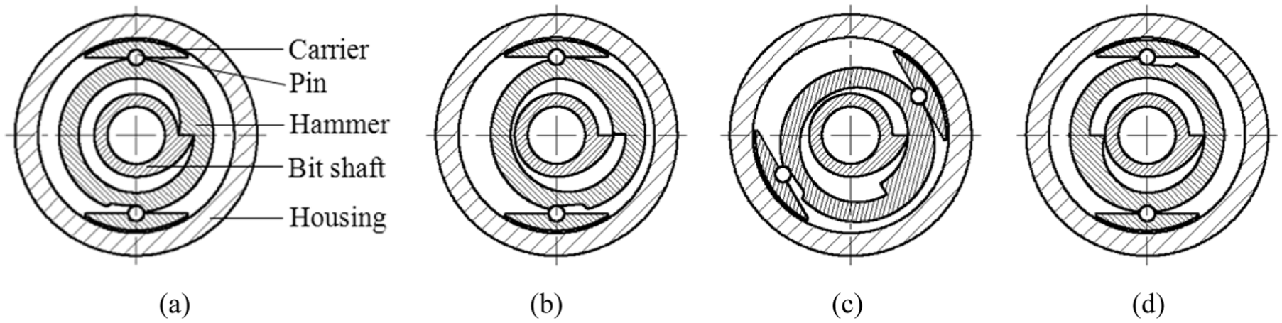
Cross-sectional views of the impact unit, illustrating the sequential views of the movement of the impact unit. 26
The rotational impact drill assembly has a lower connection to the drill bit and an upper connection to other drilling tools. The WOB and torque from the rotary table are imparted through the housing and upper end of the bit shaft, including splines of the two components. The drilling fluid from the surface flows into the assembly and then into the bore of the housing. The fluid flows into the annular space of the turbine motor and then is conducted into a bore of the bit shaft through several ports in the drive shaft. Finally, the fluid flows to the drill bit. Due to the facts that the turbine stators are fixed in the housing and that the turbine rotors are fastened on the drive shaft and able to rotate, the drive shaft is rotated with the turbine rotors driven by the fluid. Then, the carrier which is threaded to the drive shaft rotates in a same velocity of the turbine rotors and rotation of the carrier also rotates the hammer. As the drive shaft rotates periodically driven by the turbine motor, anvil of the hammer and anvil of the bit shaft are coupled to impact. By this way, the hydraulic energy of the drilling fluid is transferred into kinetic energy and then is imparted to the bit.
In operation, anvil of the hammer decouples or is released from anvil of the bit shaft. The hammer moves between concentric and eccentric positions around the bit shaft. Each revolution of the drive shaft makes the hammer strike contact with the bit shaft for rotatably and periodically impacting the drill bit. The impact on the bit converts the kinetic energy into increased torque. After each impact, the hammer is able to disengage from the bit shaft and rotates once again to generate impact. Consequently, repeated and periodical impacts are generated to intensify the torque at the drill bit, which can be used to reduce the build-up of torque on bit. The drive shaft moves axially uphole when the bit is drilling (on bottom) and moves downhole when the bit is not drilling (off bottom). When the bit is off bottom, the capping nut moves axially and engages a frictional braking interface formed by the disk and capping nut. Although frictionally restrained, the drilling fluid can still flow through the turbine motor and then to the drill bit.
Since vibration of the drillstring consumes energy, the energy will be most effectively used if it is directly and considerably absorbed by the rock rather than being absorbed by the drillstring. There exists a rotational tolerance used to decouple rotation of the bit shaft from the housing (Figure 2(a)). Four 45° annular gaps are circumferentially spaced on the bit shaft and four 40° housing dogs are circumferentially spaced on the housing. When drilling, rotate speed of the bit shaft is bigger than that of the drillstring and thus is driven ahead of the housing momentarily, giving rise to an effective transmission of the energy to the drill bit. Also, it can be concluded that the bit shaft rotates with a limited independent capability of 5°. Combining with rotation of the drillstring, periodical ahead of the housing is ensured for the bit shaft.
System of Halliburton
In 2004, the Halliburton Energy Service Inc. developed a rotary impact drilling system for the oil and gas drilling in tough formations. 27 The system is applied for generating rotary percussive impacts to the drill bit so that stick-slip vibrations can be mitigated and relatively large loads in the axial direction can be avoided. The system can be arranged in the drillstring between a power motor and the drill bit. When encountering a tough formation, percussive force is applied to the drill bit through an anvil in the term of driving a hammer due to fluid flowing. Hydraulic energy of the drilling fluid is transferred into kinetic energy of the hammer through a turbine head, which is then imparted to the drill bit.
The rotary impact drilling system is schematically shown in Figure 4. The system contains a housing, a drive unit, an impact unit, an anvil, a lock unit, and a bushing. The housing is directly connected to a drill collar or a power motor at its upper end and to the bit at its lower end, which tapers radially outwardly to form a cylindrical anvil. In the upper end of the housing, there is a shoulder used to limit the axial displacement of the anvil. The anvil which is a sophisticated and complicated component extends upwardly from the drill bit and then into the housing. A flange that forms a seat for a disk of the drive unit protrudes above the upper end of the anvil and a shoulder formed on the outer surface of the anvil for limiting axial movement of the anvil is adapted to engage the bushing. A central axle around which a helical spring is wrapped is formed in the anvil. Two chambers are diametrically positioned in the anvil, which are used to arrange the two impact hammers. Also, two bypass chambers are diametrically positioned in the anvil, wherein one venture surface is formed in each bypass chamber. Both the two chambers and the two bypass chambers are in fluid flow communication with the bore of the anvil in its below end. A series of passages are designed for the bypass chambers to communicate with the chambers.
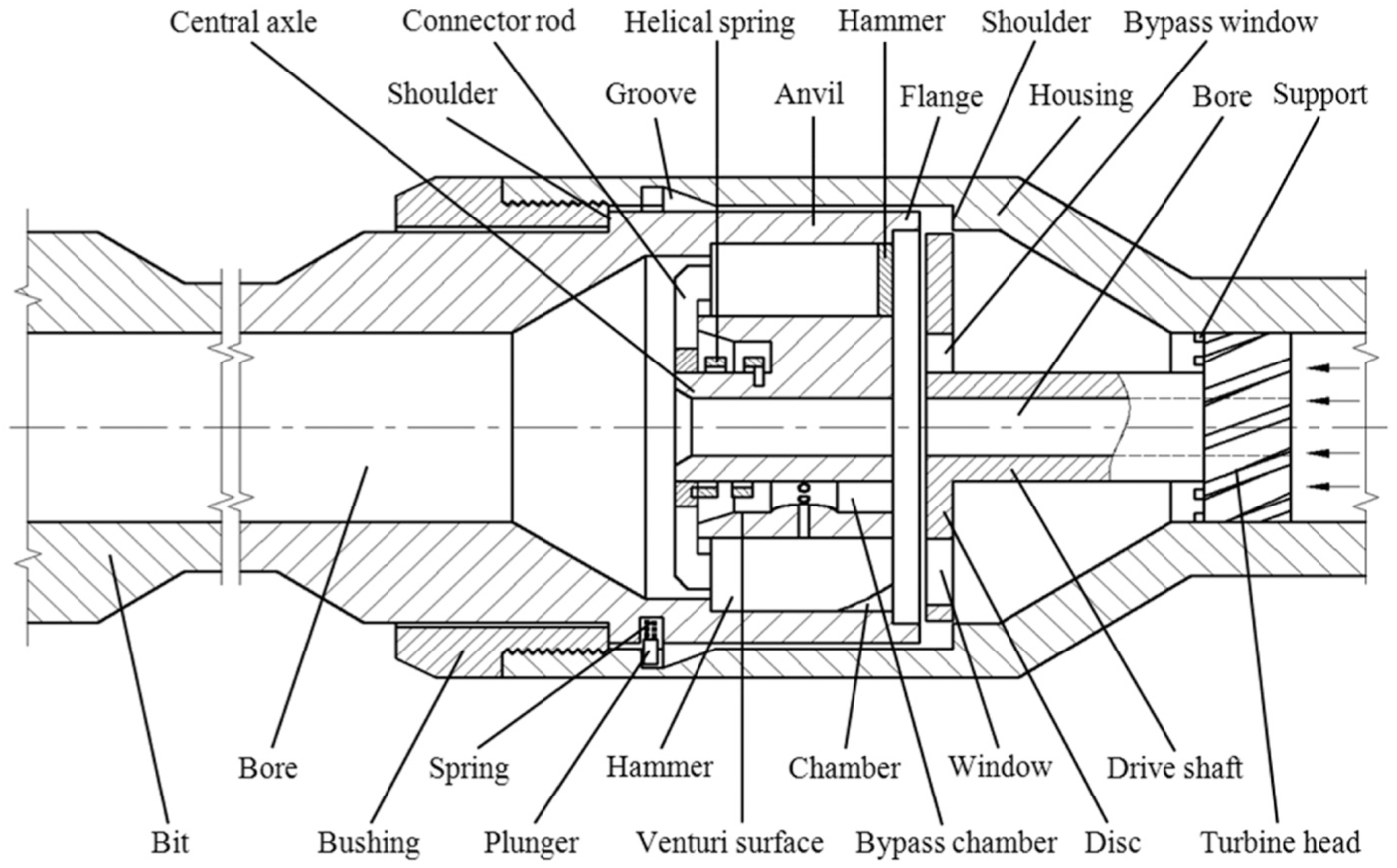
Structure diagram of the rotary impact drilling system of the Halliburton Energy Services Inc. 27
The drive unit is composed of a turbine head, a drive shaft, and a disk. The turbine head is held up by numerous supports for limiting its axial displacement. The disk is connected to the turbine head through the drive shaft wherein a bore is formed. In the disk, there are two windows and two bypass windows which are developed to registry with the two chamber and two bypass chambers, respectively. The impact unit is composed of two impact hammers, a helical spring, and a connector rod. Isometric view of the hammer used to generate impacts is shown in Figure 5. Lengths of the hammers are smaller than that of the chambers, permitting limited rotation of the hammers in the chambers. The tongue guide of the hammer is used to align and guide the movement of the hammer. The helical spring wraps around the central axle, with one end of the spring being fixed to the anvil and the other being fixed to the connector rod. The connector rod extends from the bases of the two hammers to connect them so that the two hammers are synchronous. The lock unit comprises a series of springs and plungers, which are used to control the relative rotation and movement of the anvil to the housing. The bushing is designed to support the anvil and also to limit the axial movement of the anvil.

Isometric view of the impact hammer. 27
The housing drives the anvil to rotate and thus delivers the torque on bit from rotary table through the lock unit. In one condition, the WOB is delivered from the housing to the anvil through the lock unit acts on the tapered surface of the housing. In addition, the WOB may be delivered from the shoulder in the housing to the upper end of the anvil when relative large loads are acted on the bit. The drilling fluid from the surface flows into the system and then into the bore of the housing. In a normal mode, the driven unit is frictionally restrained by the support and the fluid flows through the bore of the drive shaft into the area between the disk and the upper surface of the anvil. For this case, the disk does not rotate and the hammers do not work. The fluid flows through the chambers to the bore and in the end to the bit, which means that the hammers are not affected by this fluid flow. In the other mode, the anvil is forced to move upwardly when a relative large axial load from the formation is encountered on the bit, making the flange to engage the disk to block the fluid between the anvil and the disk and causing the plungers to move upwardly to the top of the tapered grooves, which decouples the anvil from the housing. For this case, the flow between the anvil and the disk will be blocked, forcing the fluid to flow the inclined fluid passages and thus the turbine head is driven to rotate.
Rotation of the turbine head causes rotation of the shaft and the disk. Then, the two windows in the disk periodically pass over and register with the two chambers in the anvil, allowing the high-pressure fluid to flow into the two chambers and to act on the drive surface. As a result, the hammers are forced to rotate in an anticlockwise direction and thus potential energy is stored in the helical spring due to its rotation. Similarly, the two bypass windows in the disk also periodically pass over and register with the two bypass chambers in the anvil, allowing the fluid to flow into the two bypass chambers when the two windows are not in registry with the two chambers. In addition, two low pressure zones are established, respectively, due to the venture surface associated with the two bypass chambers, inducing the fluid in the chambers to flow to the bypass chambers through the passages. Thus, the hammers are rotated in a clockwise direction due to release of the potential energy stored in the helical spring, causing the impact face of the hammer to strike the anvil. In this way, percussions are generated and then are imparted to the bit. With the continue rotation of the disk, the above operation is repeated and the hammers reciprocate back and forth within the anvil, delivering high-frequency torsional impacts to the bit.
Figures 6 and 7 are presented to assist in understanding the structure and principle of the system. Figure 6 shows the cross-sectional views taken along the upper end of the flange, those views are in a mode that the flange does not engage with the disk. Figure 6(a) shows the hammers are forced by the fluid to move in the chambers in an anticlockwise direction and Figure 6(b) shows the hammers rotate in a clockwise direction due to release of the potential energy stored in the helical spring. Figure 7 shows the cross-sectional views taken along the upper end of the flange, those views are in a mode that the flange engages with the disk because the drill bit encounters a relatively large load. Figure 7(a) shows the windows registries with the chambers and Figure 7(b) shows the bypass window registries with the bypass chambers.

Cross-sectional views taken along the upper end of the flange, which are in a mode that the flange does not engage with the disk: (a) the hammers are forced by the fluid to move in the chambers in an anticlockwise direction and (b) the hammers rotate in a clockwise direction due to release of the potential energy stored in the helical spring. 27

Cross-sectional views taken along the upper end of the flange, which are in a mode that the flange engages with the disk because the drill bit encounters a relatively large load: (a) the windows registry with the chambers and (b) the bypass window registries with the bypass chambers. 27
Tool of Sinopec
In 2010, Sinopec developed a torsional impact drilling tool that can generate high-frequency torsional impacts for improving rate of penetration (ROP). This torsional impact drilling tool aims at the hard formation or abrasive formation wherein stick-slip phenomena are frequent. The tool is arranged between the drill collar and the drill bit, providing high-frequency torsional impacts directly to the drill bit. In operation, the pressure energy of the drilling fluid is transferred into mechanical energy of an impact unit. As the drilling fluid continues to flow, the strike between a hammer and a bit shaft repeats and then continuous torsional impacts are imparted to the drill bit.
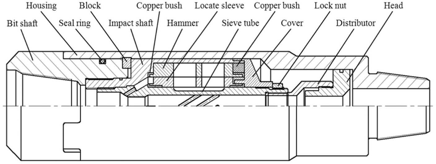
Figure 8 illustrates structure diagram of the torsional impact tool of the Sinopec. 28 The tool is composed of a housing, a bit shaft, a cover, an impact unit, numerous supports, and a series of rings. The housing couples with the lower end of the bit shaft through a group of splines. Both the torque on bit and WOB are imparted from the housing to the bit shaft and then to the bit. In fact, both the structure and the principle of the spline of this tool are similar to that of the assembly developed by the United Diamond Ltd (as presented in Figure 2). A cover is designed to block the fluid in the impact unit from flowing out at the upper end of the impact unit. Grooves are designed to distribute the drilling fluid so that part of the fluid flows through the central bore of the tool and the other part flows through the grooves and then into the impact unit to drive the impact hammer. In order to achieve this goal, the cover tapers outwardly to adjust the flow rates. The supports are designed to keep the bit shaft being retained in the housing. The rings are used to support and centralize the components of the impact unit.

Structure diagram of the torsional impact tool of the Sinopec. 28
The impact unit comprises the upper part of the bit shaft, an impact hammer, a locate sleeve, and a sieve tube. In the upper part of the bit shaft, there are a chamber for locating an impact head, a drainage, and two fluid channels. The two channels are filled with high-pressure drilling fluid used to drive the impact hammer and the drainage is used to discharge the fluid in the impact unit. The impact hammer contains a launch head and the impact head. For each of the two heads, there are two channels located close to them. The locate sleeve has two channels which are designed to registry with the two channels close to the impact head. Together with the impact hammer, a chamber is formed in the locate sleeve, and impact chamber A and B are used to represent the chamber in different conditions. The sieve tube is concentric to the bit shaft. The tube has several inclined passages used to discharge the fluid from the impact unit and a series of radial passages for communicating the tube with the locate sleeve. A nozzle in the sieve tube is used for closure of the fluid and thus part of the fluid flows into the impact unit through the radial passages in the tube.
During the operating process, the drilling fluid is divided into three parts. The first part flows through the central bore of the tool and then into the bit. The second part flows through the grooves of the cover and then into fluid channels of the bit shaft, driving the hammer to rotate once a certain channel of the hammer registers with the fluid channel. Then, this part of fluid flows into chamber A or chamber B and is discharged via the drainage. The third part flows to the radial passages and then into chamber X or chamber Y via the channels in the locate sleeve and the channels of the hammer which are close to the impact head. The channels of the hammer are also used to discharge the fluid in the chamber. Figure 9 shows the cross-sectional views of the torsional impact tool, which illustrate the sequential presentations of the impact unit for different running conditions.

Cross-sectional views of the torsional impact tool, which illustrate the sequential views of the impact unit for different running conditions: (a) the hammer and the locate sleeve moves in clockwise direction, (b) the hammer stops rotating and the locate sleeve continues to rotate in clockwise direction because of inertia, (c) the hammer and the locate sleeve moves in anticlockwise direction, and (d) the hammer stops rotating and the locate sleeve continues to rotate in anticlockwise direction because of inertia.
In order to describe the principle of the impact unit, the tool is assumed to be in a state shown in Figure 9(a). As can be seen from the figure, the hammer rotates in a clockwise direction and hits the bit shaft. At the same time, the locate sleeve is driven by the launch head of the hammer to rotate. Due to the impact between the hammer and the bit shaft, the hammer stops rotating. The locate sleeve, however, continues to rotate because of inertia and leads to a shrink of the chamber A. On one hand, the drilling fluid in the chamber A is squeezed and then is discharged through the drainage. On the other hand, chamber B is expanded due to injection of high pressure in the fluid channel. During this process, chamber A shrinks and chamber B enlarges. An illustration to show the final state of this process is shown in Figure 9(b). For this state, the locate sleeve stops rotating clockwise since the chamber A vanishes. With a sustained action of the high-pressure fluid, the hammer rotates in an anticlockwise direction. Also, the locate sleeve rotates synchronously, being driven by the launch head. In the meantime, chamber X shrinks and chamber Y enlarges. Chamber Y is expanded by the high-pressure fluid from the radial passages of the sieve tube. Since the chamber has a limited rotation, then the impact head impacts the anvil in an anticlockwise direction. The final state of this process is shown in Figure 9(c). For this state, the hammer stops rotating, but the locate sleeve continues to rotate due to inertia. During this process, chamber B shrinks and discharges the drilling fluid into the drainage that is at a low pressure. Chamber A, however, is expanded under the action of the high-pressure drilling fluid from the fluid channel. As chamber B shrinks, the locate sleeve stops rotating anticlockwise when chamber B vanishes. The final state of this process is illustrated in Figure 9(d). Then subsequently, both the impact hammer and the locate sleeve are driven to rotate clockwise. The impetus for driving the unit comes from two parts, one is the high-pressure fluid in chamber A and the other one is the high-pressure fluid in chamber X, and this part of fluid is from the radial passages of the sieve tube. During this process, chamber Y shrinks and chamber X enlarges, coming into a state shown in Figure 9(a).
Rotation of the impact hammer results in impactions on the bit shaft. During the drilling process, the impact chamber alternates between A and B and the launch chamber alternates between X and Y. A certain coupling of the hammer and the locate sleeve causes a launch of the impact unit of rotating clockwise or anticlockwise. The power for driving the impact unit comes from both the fluid in the fluid channel which flows through the grooves of the cover and the fluid flows through the radial passages of the sieve tube and then into the impact chamber via passages in the hammer and the locate sleeve. The fluid in the launch chamber is discharged into the drainage and the fluid in the impact chamber is discharged into the low pressure zone formed by the hammer and the locate sleeve. The low pressure zone is connected to the bore of the tool through the inclined passages. As the drilling fluid continues to rotate, torsional impacts are periodically generated. Since the bit shaft is connected to the drill bit, those repeated impacts are directly imparted to the bit to improve the ROP.
Generator of Ulterra
Ulterra Drilling Technologies Ltd developed a torsional impact generator for drilling difficult formations. 29 The generator sits in the drillstring above a PDC bit and addresses the stubborn problem of stick-slip vibration by providing auxiliary energy. The hydraulically driven tool applies high-frequency torsional impacts to the drill bit, which ensures steadier rotation and less stick-slip vibration. Structure diagram of the torsional impact generator is shown in Figure 10. In fact, both structure and principle of this generator are similar to that of the tool developed by Sinopec. The biggest difference is that for this generator two impact heads act on the bit shaft at the same time. Consequently, the structure and working principle of this generator will be briefly presented.
Structure diagram of the torsional impact generator of the Ulterra Drilling Technologies Ltd.
As can be seen from Figure 10, an impact shaft wherein the upper end has chambers for arranging impact hammers is threaded into the bit shaft. Several blocks inserted into the housing are used to keep the bit shaft from separating from the housing. Several copper bushes are designed in the generator, which are used to support and centralize the rotating components such as the locate sleeve and the sieve tube because of their good friction properties. A lock nut is threaded onto the sieve tube to compress the cover so that the drilling fluid in the impact unit can be blocked. There are many passages in the distributor so that part of the drilling fluid can flow into the impact unit through the fluid channels of the impact shaft. A head is designed and threaded into the distributor. In addition, several seal rings are designed in the tool.
Figure 11 shows the cross-sectional views of the torsional impact generator, which illustrate the sequential views of the impact unit for different running conditions. For the convenience of understanding the principle of the generator, a state shown in Figure 11(a) is used to start the description. The hammer stops rotating clockwise due to the strike on the impact shaft, but the locate sleeve continues to rotate clockwise due to inertia. Also, the high-pressure fluid in the fluid channels drives the locate sleeve to rotate clockwise. Then, the impact unit comes to a state shown in Figure 11(b). Under the action of the high-pressure fluids in the fluid channels of the impact shaft and radial passages of the sieve tube, both the hammer and locate sleeve rotate anticlockwise. The final state of this process is shown in Figure 11(c). The hammer stops rotating anticlockwise due to the strike on the impact shaft but the locate sleeve continues to rotate anticlockwise because of inertia and drive force of the high-pressure fluid in the fluid channels. Then, the impact unit comes to a state shown in Figure 11(d). Then subsequently, both the hammer and the locate sleeve are driven to rotate clockwise, with the action of high-pressure fluids in the fluid channels of the impact shaft and radial passages of the sieve tube. Once again, the impact unit comes to a state of Figure 11(a). As the drilling fluid keeps flowing, this process repeats and torsional impacts are periodically generated and then are imparted to the drill bit.

Cross-sectional views of the torsional impact generator, which illustrate the sequential views of the impact unit for different running conditions: (a) the hammer stops rotating clockwise and the locate sleeve continues to rotate clockwise, (b) both the hammer and locate sleeve rotate anticlockwise, (c) the hammer stops rotating anticlockwise and the locate sleeve continues to rotate anticlockwise, and (d) both the hammer and the locate sleeve are driven to rotate clockwise.
Comments for the tools
For the assembly developed by the United Diamond Ltd, it is problematic. First, the stops are too weak to support the forces. As can be seen from Figure 1, the drag force on the bit is finally exerted on the stops of the disk. Since the drag force may be very large when sticking of the bit happens, the stops are easy to fail and thus it is dangerous for the drilling. Second, the carrier is too weak because huge impact force is acted on it. A carrier with this structure is easy to break, which has been practically testified by the authors. Third, the components are difficult to be assembled or be disassembled. Since the turbine stators should be tightly compressed by the bushings, as can be seen from the figure, it is of great difficulties to realize this. In application, an adjustable component is suggested being used to compress the turbine motors. In addition, a baffle ring locates below the disk, which makes the disassembly of the disk from the housing be difficult.
The system of Halliburton Energy Service Inc. is impracticable. As can be referred to David, 27 the anvil moves upwardly and is decoupled from the housing when the bit stops rotating as a result of encountering a relatively large axial load. In this condition, the fluid flow causes rotation of the turbine head and corresponding rotation of the disk and then torsional impacts are generated. However, the torque from the table cannot be imparted to the drill bit because the anvil is free to rotate relative to the housing, which is opposite to the idea of adding an auxiliary energy to the drill bit. Another problem of the system is that the friction between the disk and the upper end of the anvil resists rotation of the disk. The contradiction between the friction of the two parts and leakage of the drilling fluid makes the system to be inapplicable. In addition, as described in the reference, the hammers are not affected by the fluid flow when the disk does not rotate and the blockage of flow between the anvil and the disk also terminates fluid flow through the drive shaft. From this, it can be concluded that all the fluid flows through the chambers in all conditions and that the only difference is the hammer does not rotate in normal drilling and it rotates when a large load is encountered on the bit. This, however, is contradictory to the structure of the system.
Safety is a very important factor for the drilling operation. For the tool of the Sinopec, supports of the tool are too weak to bear a large axial load such as a load from the bit when sticking of the bit happens. In fact, the supports are difficult to be installed in terms of the tool structure as illustrated in Figure 8 because a gap for moving the supports into the chamber between the bit shaft and the housing has not been designed. The tool may face another problem: the contradiction between the friction and the leakage. In more detail, on one hand, it is not appropriate for the cover to tightly compress onto the impact unit because this may lead to inflexible rotations of the hammer and the locate sleeve. On the other hand, a big clearance between the cover and the impact unit may lead to leakage of the drilling fluid and subsequently invalidation of the torsional impact tool. Also, the tool developed by Ulterra Drilling Technologies Ltd faces with this contradiction. In addition, anticlockwise torsional impacts are also generated in the tools, which may have side effects on the drilling and on the thread.
Design of new HFTIG
The newly designed tool is based on the assembly developed by the United Diamond Ltd shown in the previous section. As a result, principle of this tool is similar to the existing one. Since the existing structure is problematic, a number of improvements on the drawbacks have been made. In this section, we do not endeavor into a comprehensive description of the structure and principle of this tool; however, the main features of these improvements will be outlined with reference to the figures.
The newly designed tool 25 is schematically shown in Figure 12. A connector that is threaded into the housing is designed to solve the problems of assembling and disassembling of the assembly. There is a step in the housing for arranging the turbine rotors which are compressed by a disk threaded into the housing. On one hand, the disk is adjustable in the axial direction for compressing the turbine rotors. On the other hand, the disk is used to support the nut which bears the axial drag force of the draw bar. In this case, the turbine motor is easy to be fixed and the tool is easy to be assembled or disassembled. For the impact unit, as shown in Figure 13, the carrier is strengthened and impact angles of both the bit shaft and the hammer are improved. In addition, the structure of the anti-fall unit is improved (Figure 14).

Structure diagram of the newly designed tool.

Cross-sectional view of the impact unit.

Cross-sectional view of the anti-fall unit.
Since the impact unit is the key unit of the HFTIG, its motion feasibility is of great importance to the development of HFTIG. In order to know the motion feasibility of the impact unit, a finite element model wherein all elements are regarded as rigid bodies is established to repeat the movement of the impact unit (the schematic of the model can be regarded as the one shown in Figure 13). In the model, fixed boundary conditions are applied to both the housing (with its inner diameter 0.15 m) and the bit shaft, and a constant velocity of 20 r/min is applied to the carrier. Since the elements are rigid bodies in the model, all boundary conditions are applied onto the reference points which couple with the elements. By carrying out the kinematics simulation of the impact unit, the motion feasibility can be obtained. For each cycle of the unit motion, there are 360 frames of output. Figure 15 shows the velocity contours of the impact unit, which are representative to repeat the motion of the impact unit. As can be seen from the figure, the impact unit moves smoothly, indicating that the design of the impact unit is successful. The results of the motion feasibility of the impact unit will provide guidance to the productions of the laboratorial impact setup and the HFTIG prototype.

Velocity contours of the impact unit (there are 360 frames in all for each cycle): (a) frame 1, (b) frame 15, (c) frame 50, (d) frame 96, (e) frame 180, and (f) frame 270.
After the verification of the impact unit through the finite element method, an experimental apparatus is needed to verify the design. For the impact unit, the structure improvements are testified by a series of laboratory experiments by using the apparatus shown in Figure 16, and the tests are conducted in Chengdu En-shine Oil and Gas Co, Ltd (China). Figure 17 shows the general view of the experimental apparatus.
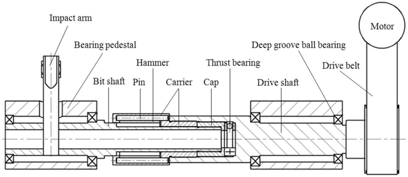
Structure diagram of the experimental apparatus. 30
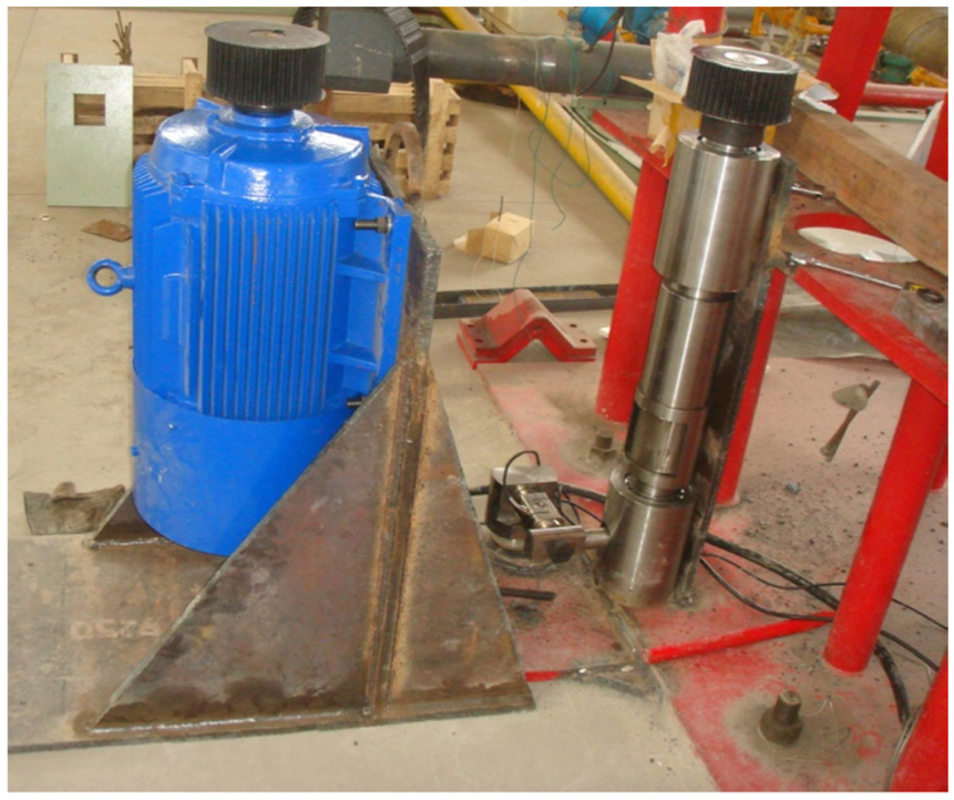
General view of the experimental apparatus.
Figure 18 shows the impact force for different impact frequencies and Figure 19 shows the impact time for different impact frequencies, which are obtained from the laboratory tests. The implementation of different impact frequencies is obtained through varying the rotational speed of the motor. In the tests, the rotational speed of the motor increases uniformly. The test results can provide input parameters for the investigation of the HFTID techniques.

Impact force for different impact frequencies. 30

Impact time for different impact frequencies. 30
Conclusion
For the drillstring in the drilling process, stick-slip vibration is prone to happen due to its large length-to-diameter ratio. This type of vibration is one of the main reasons of deterioration in drilling performance by accelerating the tool failure and lowering quality of the borehole. Numerous researches theoretically or experimentally studied the stick-slip vibration to explore the root cause of this dysfunction. In the same time, a lot of approaches for suppressing the stick slip have been presented and most of them are based on the real-time measurements. At present, active control systems through downhole measurement are most popular. Although they are useful tools for the drilling operators, there are still many shortcomings such as expensive and unstable. Based on this background, the HFTID emerges.
The HFTIG transmits high-frequency torsional impacts into the rock, providing auxiliary energy to the rock and accelerating the rock failure and thus the rock penetration rate. These impacts mitigate the reactive torque spikes in stick-slip mode and decrease the torque threshold at which the stick-slip mode is broken. Then, the bit is kept rotating with small amplitudes and the severity of the bit slipping is mitigated because the half-cycle intervals are reduced. In conclusion, the HFTIG improves the drilling efficiency by accelerating the rock crushing and mitigating the stick-slip vibrations.
Many structures have been developed since the HFTID is proposed. In this article, state-of-the-art of HFTID is studied by combining the structures and principles of the drilling tools. The assembly of United Diamond uses the turbine motor to converse the hydraulic energy into mechanical energy of the impact unit. A structure of ratchet wheel is used in the assembly to generate high-frequency torsional impacts. The system of Halliburton uses a turbine head to rotate the disk. When drilling a relative tough formation, the disk periodically registers with or passes over the anvil, driving the impact hammer to impact the anvil back and forth and generating high-frequency torsional impacts. Both the tool of Sinopec and the generator of Ulterra use the differential pressure of the passages and channels. The impact hammers rotate back and forth and thus generate torsional impacts. Then comments are, respectively, given for the four tools.
In this article, a new tool based on the assembly of United Diamond is presented. The problems of assembling and disassembling of the assembly are solved by threading a connector into the housing. The carrier is strengthened and impact angles of both the bit shaft and the hammer are improved, which are testified by a series of laboratory experiments. An anti-fall unit is designed to prevent downhole accident due to too large an axial drag force when sticking of the bit happens.
Footnotes
Handling Editor: James Barufaldi
Declaration of conflicting interests
The author(s) declared no potential conflicts of interest with respect to the research, authorship, and/or publication of this article.
Funding
The author(s) disclosed receipt of the following financial support for the research, authorship, and/or publication of this article: This work is supported by the State Key Laboratory of Mechanical Transmissions (No. SKLMT-KFKT-201615), National Natural Science Foundation of China (No. 51674214; No. 11402219), Key Research Project of Sichuan Province (No. 2017GZ0365), and Youth Scientific Research Innovation Team Project of Sichuan Province (No. 2017TD0014).