
Abstract
The oil pressure sensors are installed on the hydraulic connection device to monitor the tension of wire ropes. The change of acceleration during the operation process of hoist causes the tension change of each wire rope. It leads to impact on the cylinder of hydraulic connection device, enlarges the pressure loss, and makes the non-linear friction become more complex which affects the monitoring accuracy. In this article, the mathematical model of hydraulic connection device is established. To analyze the dynamic characteristics of the hydraulic connection system, the model of single hydraulic cylinder and hydraulic connection device is established and simulated by AMESim software. Then, the friction and pressure compensation in the working process of hydraulic connecting device are obtained by LuGre friction model and corresponding formulas of pressure loss. Finally, the monitoring system is designed and real-time compensation test is carried out. The results show that the compensation improves the accuracy of the real-time measurement system of wire rope tension.
Keywords
Introduction
During the operation process of multi-rope friction hoist, excessive tension of wire ropes and lifting load may cause the wire rope abrasion or breakage which may cause cage falling and even casualties. In order to avoid these accidents, it is necessary to monitor the tension of wire ropes accurately. Oil pressure method is a common way to achieve tension monitoring. In this method, oil pressure sensors are installed on the tension balance hydraulic connection device. However, due to the non-linear friction caused by the motion of piston to cylinder wall and the oil pressure loss caused by the oil flow in the hydraulic connection device, tension measurement results are inaccurate. In order to solve this problem, the dynamic characteristics and compensation of wire rope tension based on oil pressure sensor are studied in this article.
The wire rope of multi-rope friction hoist is connected with the hoisting container through the hydraulic connection device. 1 The structure is shown in Figure 1. The connecting assembly 8 connects each cylinder, which is mainly composed of hydraulic hoses, valves, and through pipes. 2 When the tension of each wire rope is different, the hydraulic cylinder linked with the wire rope with greater tension will compress the piston rod, extend the suspension, and reduce the tension of the wire rope. Meanwhile, the oil in the cylinder will enter the cylinder connected by the wire rope with less tension through the connecting assembly 8, which makes the piston rod extend, the suspension short, and increases the tension of wire rope. Then, the tension of each wire rope becomes equal. This device can prevent the wire rope from breaking when the difference of each tension is too large, and also buffer the mutation of wire rope load caused by the change of acceleration.3,4 The oil pressure sensor is installed on the bypass of each cylinder, and the outer hydraulic pipeline is fixed to the rod-less cavity of each hydraulic cylinder, and four hydraulic pipelines are connected with steel pipes. The tension of each wire rope can be obtained by multiplying the oil pressure and the bearing area of piston. 5
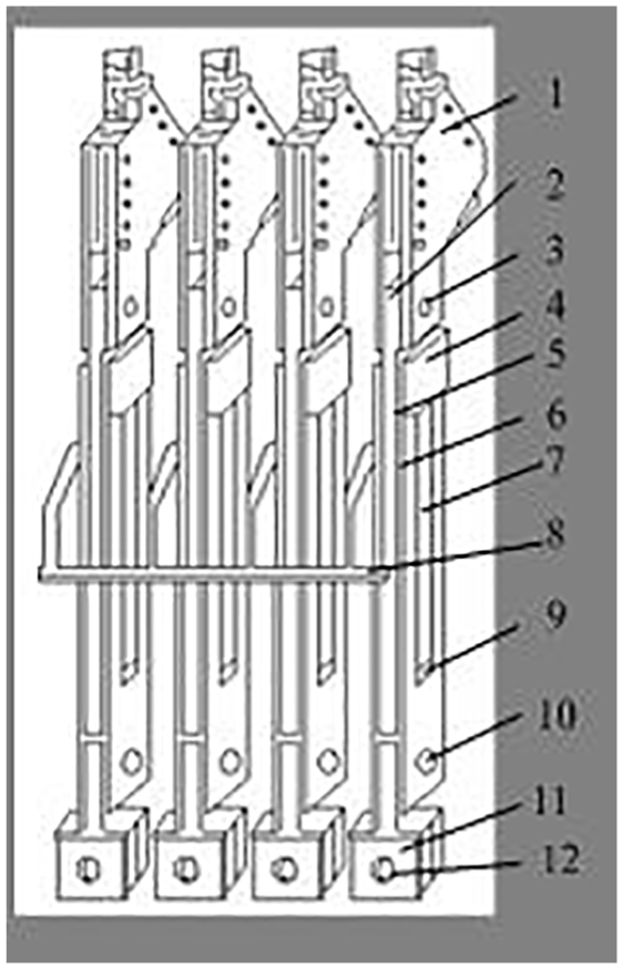
Structure of wire rope tension balance hydraulic connection device.
Domestic and foreign scholars have done a lot of work on the design of wire rope tension and load monitoring system. Many countries have developed the instruments for measuring the tension of wire rope.6–8 Sweden ABB company invented a pin-shaft-type elastic element in series with the wire rope which is named HAMB dynamic tension tester. 9 In 1995, Beus and Mccoy 10 used a new type of force sensor to detect the wire rope tension, so as to determine whether the status of wire rope is slack or tense. In 2004, Wang et al. 11 put forward a scheme of dynamic wire rope tension monitoring system for multi-rope hoist. Meanwhile, they proposed a sleeve hydraulic sensor structure and an induction signal transmission mode of wire rope. Liu et al. 12 and Zhang and Jin 13 designed a wheel-spoke elastomer pressure sensor to measure the wire rope tension and analyzed its application.
The tension and load of wire rope are measured by installing oil sensors on the hydraulic balancing device. Generally, there are tension conversion pressure method and oil pressure measuring method.14,15 The former is to install a pressure sensor between the piston rod and the pressure block, and the tension signal of the wire rope measured by the pressure sensor involves violent fluctuation and noise, which cannot effectively reflect the tension and load of wire rope. This article uses oil pressure sensor to measure the tension signal, which can effectively eliminate the tension fluctuation of wire ropes. The accurate measurement of the tension and load of the wire rope can be realized by effective compensation of the oil pressure and friction force. 16
Hydraulic cylinder is an important part of hydraulic balancing device whose dynamic characteristics affect the wire rope tension. Guan et al. 17 took a balance circuit of hydraulic lifting system as the research object. A simulation model of hydraulic balance circuit was built by AMESim software. Relevant simulation parameters were set and dynamic characteristics were analyzed. Si and Zhao 18 introduced the hydraulic system of the composite chassis of wheel and crawler which was modeled and simulated by AMESim software. Zhang et al. 19 used AMESim to simulate and analyze the hydraulic system and used the established HCD simulation model to analyze the factors affecting the motion speed of the hydraulic cylinder, which provides a basis for the design and fault diagnosis of the hydraulic system.
The dynamic friction compensation of hydraulic cylinder is of great significance to improve the monitoring accuracy of wire rope tension. The common friction models include Kulun model, Kulun–viscous model, static friction–Coulomb–viscous model, Stribeck friction model, Karnopp friction model, and LuGre friction model. Kulun model, Kulun–viscous model, and static friction–Coulomb–viscous model belong to linear friction model. Stribeck friction model cannot accurately describe the friction when the oil speed is zero. Karnopp friction model is more complex and inconvenient. However, LuGre friction model belongs to non-linear friction model, which can describe the dynamic characteristics of friction near zero speed accurately and can also describe a variety of dynamic friction phenomena. Therefore, the LuGre friction model is widely used. Wei et al. 20 applied the LuGre friction model to solve the complex friction model of the pneumatic servo system which improved the dynamic and steady-state performance of servo system. Guo et al. 21 selected the LuGre friction model to describe the non-linear friction of the test turntable and eliminate the effect of non-linear friction on test turntable. In this article, the friction force in the working process of hydraulic connecting device is analyzed. Taking into account the characteristics of non-linear friction caused by the motion of piston to cylinder wall in hydraulic connecting device, the LuGre friction model is adopted for friction compensation in this article.
The mathematical model of the hydraulic connection system
The wire rope connected with the hydraulic connecting device can be regarded as a spring system, and the connecting hydraulic cylinder can be regarded as a damping system. The wire rope–hydraulic cylinder can be considered as a spring–damping system without mass. Figure 2 shows the established mathematical model of the hydraulic connection system in which the four hydraulic cylinders are connected. Here, we select the force analysis of an oil cylinder as the example.

The mathematical model of hydraulic connection system.
The dynamic equation of piston force is described in equation (1)

where m represents the mass of the piston,
When the hydraulic cylinder piston mass m is ignored, equation (1) can be described as equation (2)

The dynamic equation of hydraulic cylinder body force is described in equation (3)

where
When the hydraulic cylinder body mass

Comparing equations (2) and (4), the tension of wire ropes and the lifting load is approximately equal during the operation process of the hoisting system.
The simulation study of hydraulic connection system
To analyze the dynamic characteristics of the hydraulic connection system, the models of single hydraulic cylinder and hydraulic connection device are established and simulated by AMESim software. First, the dynamic characteristics of single hydraulic cylinder under different loads, friction, and flowrate are analyzed. Second, the influence on pressure, flowrate, and speed of the connecting device caused by load change and pressure impact is analyzed. They are helpful to understand the dynamic characteristics of hydraulic connection system in the process of measuring tension and load more deeply. They are also useful to select the more effective compensation model to achieve more accurate measurement. 22
Modeling and simulation results of single hydraulic cylinder
AMESim modeling of single hydraulic cylinder
The electromagnetic directional valve can control the movement of the hydraulic cylinder piston, and there are overflow valves in the oil return circuit. In Figure 3, the load variety can be simulated by adjusting the pressure of the overflow valves. The simulation parameters are shown in Table 1.
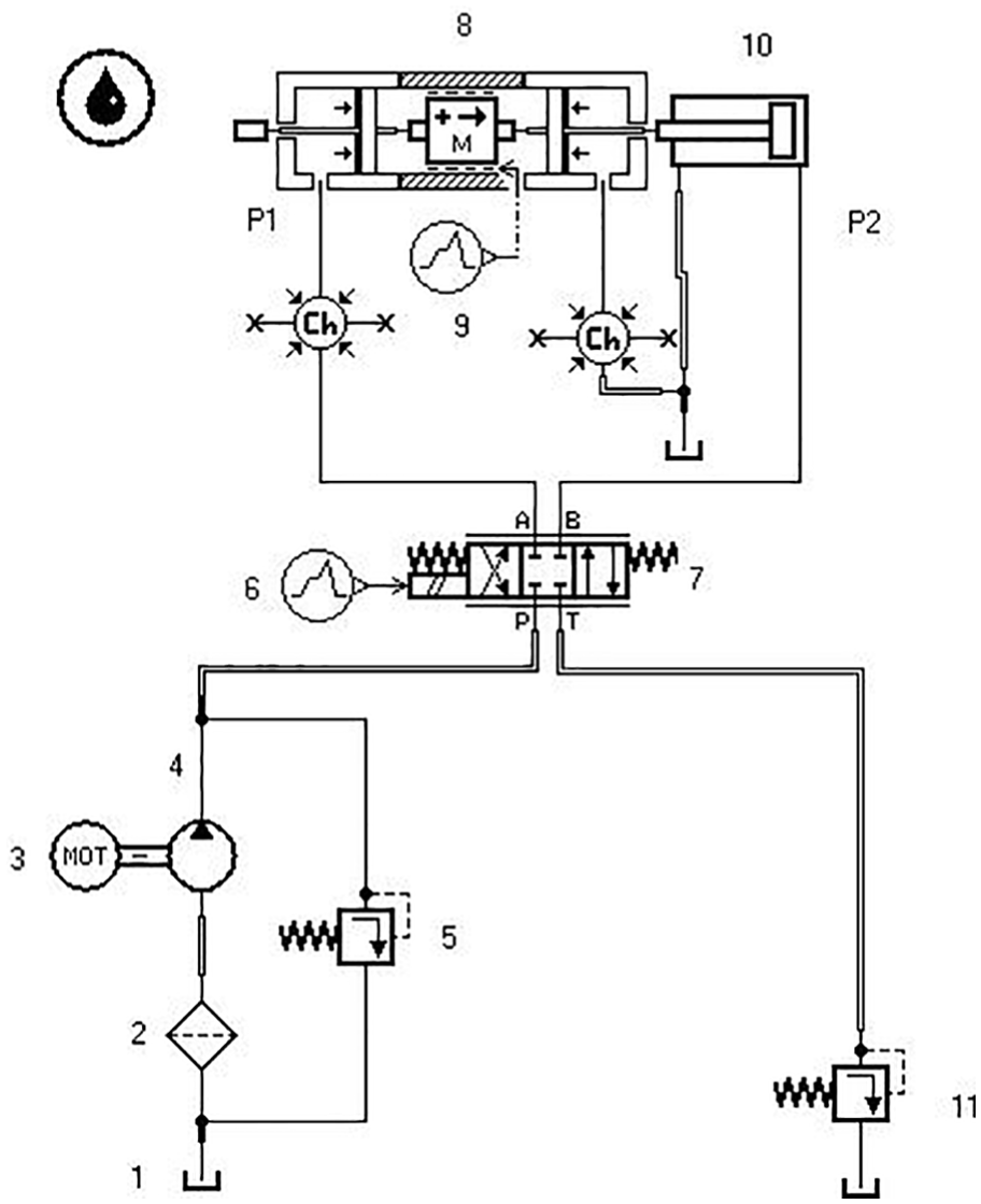
AMESim model of single hydraulic cylinder.
Simulating parameters of single hydraulic system.

Simulation of reciprocating motion of single hydraulic cylinder
Pressure characteristics of hydraulic cylinders under different load pressures
The load pressure of the back pressure loop is set to 10, 8, 6, 4, 2, and 0 MPa, respectively, and the flowrate is 20 L/min, which is shown in Figure 4. When the pressure becomes greater, the fluctuation time becomes longer and the fluctuation becomes smaller. Taking the back pressure curve of 10 MPa as an example, the maximum fluctuation pressure of rod-less cavity is 10.6 MPa within 0.3 s and the pressure is stable after 0.3 s, which is equal to 10.26 MPa. The stable pressure is 0.26 MPa larger than the back pressure load, namely, the pressure loss is 0.26 MPa. Besides, the non-linear friction is caused when the piston moves in hydraulic cylinder. The influence of friction on the pressure variation in the rod-less cavity is shown in Figure 5. When the friction becomes smaller, the pressure fluctuation and the fluctuation time become greater and longer, respectively.

Pressure variety of rod-less cavity.

Effect of friction on the pressure of rod-less cavity.
Characteristics of hydraulic cylinder under different flowrates
The flowrate of the hydraulic pump is set to 20, 10, 5, and 3 L/min, respectively. And the load pressure of the back pressure loop is set to 10 MPa. Figure 6 shows that the pressure loss is different under different flowrates. When the flowrate of hydraulic pump becomes larger, the pressure fluctuation of the cylinder rod-less cavity becomes larger, and the needed time for pressure of balance cylinder reaching load pressure becomes shorter.

Pressure curves of rod-less cavity under different flowrates.
Reciprocating motion of hydraulic cylinder
The motion direction of the piston of the hydraulic cylinder changes irregularly with the speed variety of the hoist. The change of piston direction affects the pressure of the rod-less cavity when the friction of the hydraulic cylinder exits. According to Figure 7, two curves represent the simulation results without friction and with friction, respectively. The hydraulic cylinder produces two reversals at 1 and 2 s. When the hydraulic cylinder reverses, the oil pressure in the rod-less cavity will fluctuate.

Pressure variety under different friction.
Modeling and simulation results of hydraulic connection device
Modeling of hydraulic connection device
Figure 8 shows the model of the hydraulic connection device established using AMESim software.
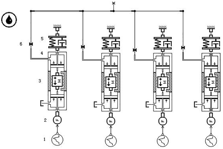
Model of hydraulic connection device.
Simulation analysis of hydraulic connection device
When the hydraulic connecting device works, the variety of oil pressure and flow occurs in the pipeline inevitably, which causes great effect on the stability of the hydraulic system and the measurement accuracy of wire rope tension:
Figure 9 shows the load input curves of signal sources of four balancing cylinders. The four load signals within 0–3 s increase from around 2000 N to about 5000 N in different slopes. The load changes more than 6000 N at 3 s suddenly and remains stable later.
On the condition of the characteristics of oil tube are ignored, when all the stop valves in the simulation model of Figure 8 are removed, the simulation curves of four rod-less cavities are shown in Figure 10. It shows that no matter how the load changes, the pressure in the four balance cylinders remains constant.
On the condition of the characteristics of oil tube are considered, there is a stop valve on each bypass oil tube of the hydraulic connection device as shown in Figure 8. The pressure variety curves of rod-less cavity in hydraulic connection device are obtained in Figure 11. Compared to the load signals in Figure 9, the oil pressure of the four rod-less cavities in Figure 11(a) is adjusted by the hydraulic connecting device and remained same.

Load input curves of signal source.

Pressure of four rod-less cavities.
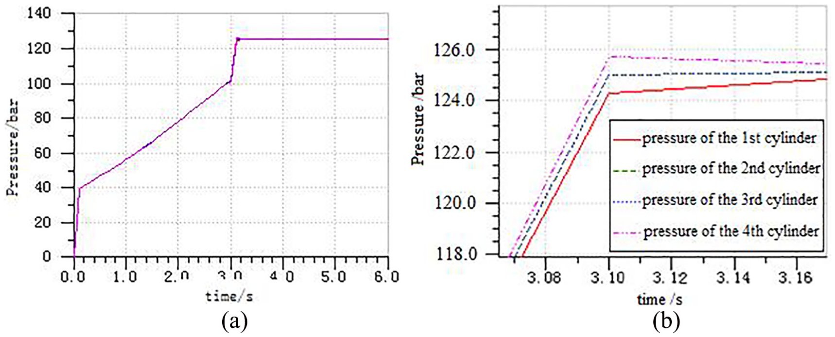
Pressure curves of rod-less cavity in hydraulic connection device.
However, it can be seen from Figure 11(b) that when the load changes suddenly, it will impact the balance cylinder and cause the difference pressure in the cylinder instantly. It can be regarded as the difference between the loads of four wire ropes. According to Figure 11(b), the fluctuation is largest at 3.1 s, and then the cylinder pressure remains stable. The pressure impact of hydraulic cylinder cannot be ignored, which affects the dynamic performance of the cylinder and the accuracy of tension measurement.
4. Figure 12 shows the flowrate curves of rod-less cavity in hydraulic connection device. The flowrates of the second and third cylinders vary within 2.9–3.1 s. The flowrate of the third cylinder increases first and then decreases. The flowrates of the first and fourth cylinders vary greatly and become unstable within 3–3.3 s. It is explained that pressure shock is the main cause of the flowrate variety in rod-less cavity.
5. Figure 13 shows the displacement variety curves of four balance cylinders in hydraulic connection device. Because the loads of the first and second cylinders are larger within 0–3 s, the cylinder produces positive movement and the oil flows out of the hydraulic cylinder. The piston displacements of four cylinders are 1, 2, −1, and 0 mm, respectively. When the load changes suddenly within 3–6 s, the load of the fourth cylinder is the largest and the load of the first cylinder is the smallest. Therefore, the displacement of the piston in the fourth cylinder is maximum, which is equal to 11 mm. The displacements of the pistons in the second and third cylinders are 1 mm, and the displacement of the piston in the first cylinder is −10 mm.
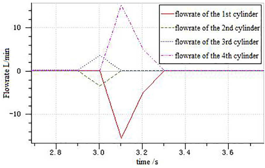
Flowrate curves of rod-less cavity in hydraulic connection device.

Displacement curves of hydraulic cylinder piston.
Comparing with the load curves of signal source in Figure 9, when the load changes drastically within 0–0.2 s and 2.8–3.4 s, it will cause great pressure impact on the hydraulic connection device. If the loads of the four cylinders are obviously different, the pressure of four cylinders will be adjusted to ensure the same internal pressure value of the rod-less cavity, which is shown in Figure 11.
Analyzing the dynamic characteristics of the hydraulic connection device plays an important role of balancing oil pressure and wire rope tension to a certain extent. However, the pressure loss caused by hydraulic oil flowing and the friction caused by piston movement will affect the accurate measuring of wire rope tension seriously.
Pressure and friction compensation of hydraulic connection device
Pressure loss
There are some characteristics such as inductance, resistance, and capacitance for the fluid in the hydraulic pipeline of balance cylinder. The viscous fluid will be influenced by the resistance of pipeline, and the energy will be dissipated in the flowing process. Lost energy mainly includes pressure loss along the pipeline and local pressure loss. 23 Pressure loss along the pipeline is caused by the viscous force occurring in fluid flowing through a straight pipe. Local pressure loss is caused by the force occurring in fluid flowing through a pipe with sudden-change diameter or a bending pipe.
The pressure loss along the pipeline is described in equation (5)

where
The local pressure loss is described in equation (6)

where
The total pressure loss is expressed in equation (7)

Analysis of non-linear friction
The non-linear friction in the hydraulic cylinder is the main factor which affects the reliability of the monitoring system. 24 In this article, the LuGre model is adopted for hydraulic cylinder seal friction. First, the data obtained from hydraulic cylinder friction test are fitted with the parameters of oil pressure and friction model. Then, the parameters of the LuGre model are estimated by fitting curves. 25
The LuGre friction model 26 is described in equations (8) and (9)


where v represents the relative velocity of the friction surface, z is the relative axial deformation between the sealing ring and the moving surface under viscous condition,
Friction test of hydraulic cylinder
The test-bed of friction test of hydraulic cylinder is shown in Figure 14. It includes a double-cylinder test stand, a hydraulic pumping station, and a computer. The test is carried out when the oil enters the rod-less cavity. The flowrate control of the hydraulic system and the test of the piston speed can be realized by adjusting the flow valve and other valves. The back pressure loop is composed of the rod-less cavity where the oil flows out of the pressure control valves. The back pressure is constant by adjusting the pressure control valves.

Friction test-bed.
When the cylinder pressure and the oil flowrate are adjusted, the oil pressure signals of the tested cylinder and the loading cylinder, the force signals of the standard sensor, and the displacement signals of the displacement sensor are recorded by LabVIEW software.
Effect of oil pressure on friction
The balance cylinder piston is equipped with a lip-shaped seal ring which will produce a deformation under the oil pressure, and the pressure makes the lip come close to the inner wall of the cylinder. When the pressure becomes higher, the friction becomes greater. The back pressure in the return circuit can be changed by adjusting the pressure control valves. Then, the pressure variation of friction model under different pressures is obtained by testing the relationship between friction and velocity under different pressures. Table 2 shows the relevant parameters of friction model.
Parameters of friction model.

Based on the parameters of friction model in Table 2, the effects of oil pressure variation on maximum static friction, Stribeck critical velocity, Coulomb friction, and viscous friction coefficient are analyzed, and the corresponding curves are fitted by the least-squares method of MATLAB. The curves are shown in Figures 15–18, respectively.

Effect of pressure variety on the maximum static friction force.
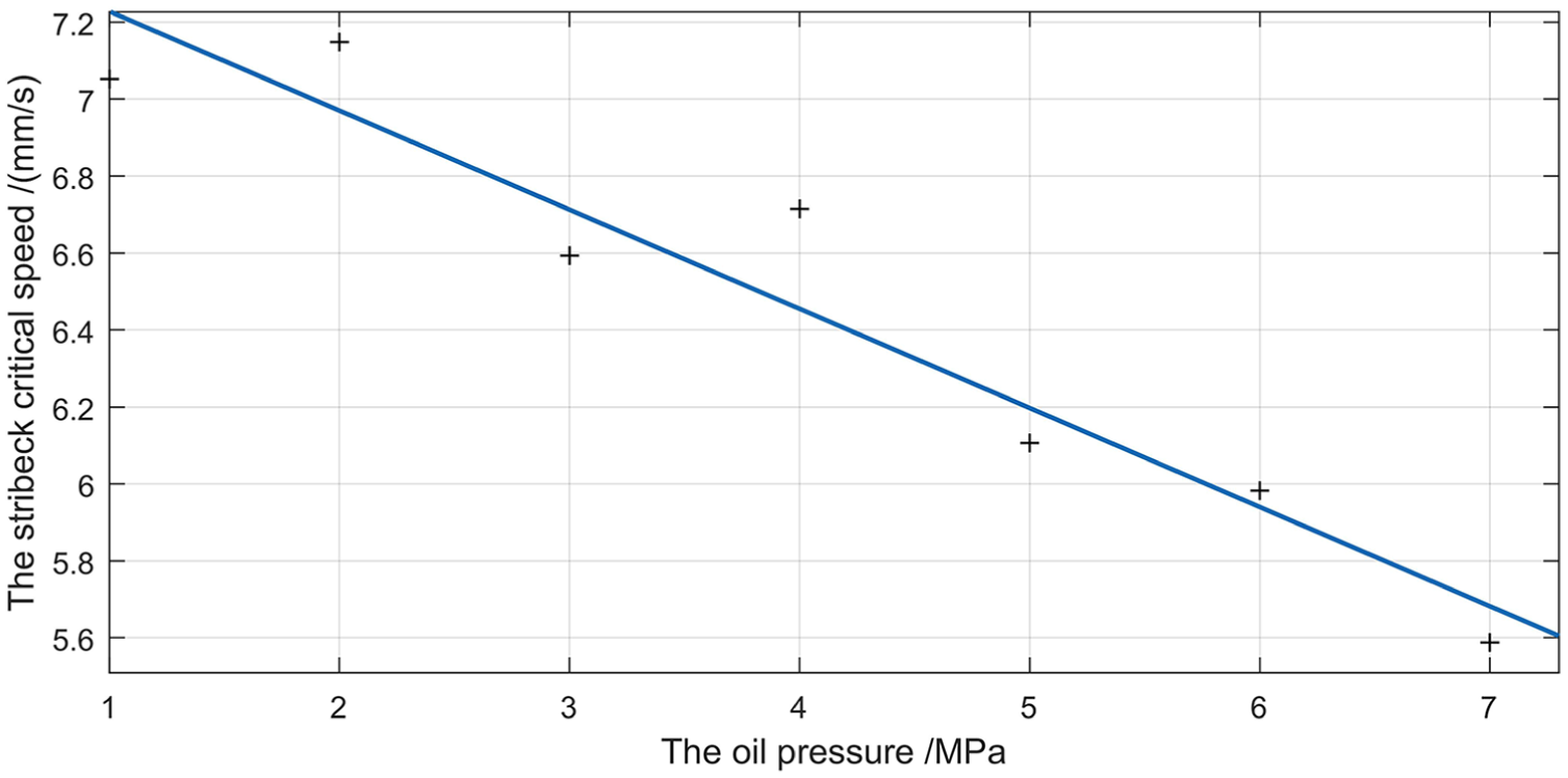
Effect of pressure variety on the Stribeck critical speed.
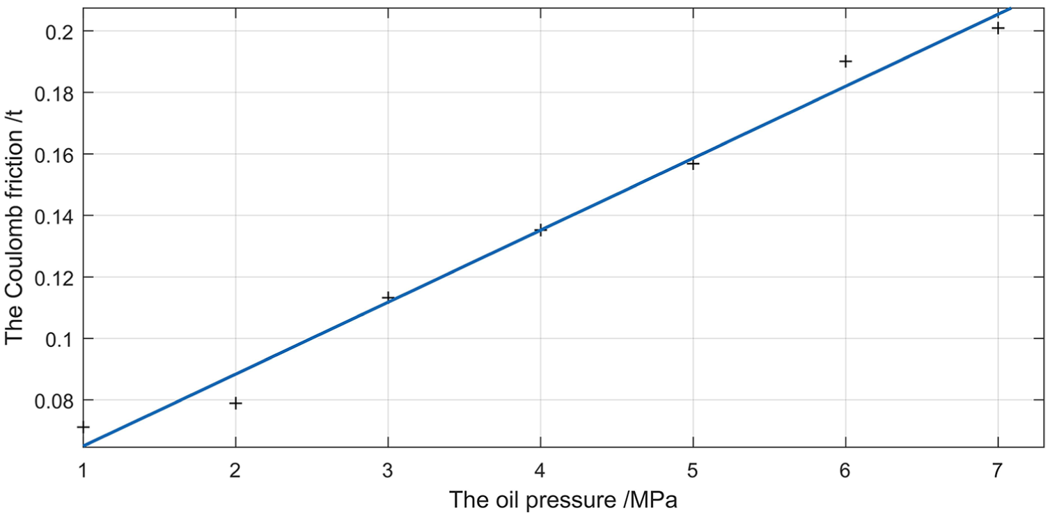
Effect of pressure variety on the Coulomb friction.

Effect of pressure variety on the viscous friction coefficient.
Figure 15 shows that the greater the oil pressure, the greater the maximum static friction force. The maximum static friction force is linear positive correlation with the oil pressure, and the correlation coefficient is 0.984.
As shown in Figure 16, when the oil pressure becomes greater, the Stribeck critical velocity becomes smaller. The Stribeck critical velocity is linear negative correlation with the oil pressure, and the correlation coefficient is 0.919.
As shown in Figure 17, when the oil pressure becomes greater, the Coulomb friction becomes greater. There is a linear positive correlation between the Coulomb friction and the oil pressure whose correlation coefficient is 0.986.
It is shown in Figure 18 that the greater the oil pressure, the greater the viscous friction coefficient. There is a linear positive correlation between the viscous friction coefficient and the oil pressure whose correlation coefficient is 0.986.
Their linear correlation coefficients are greater than 0.9, which indicates that the correlation degree is high and the fitting effect is good.
The relationship between Fs, vs, Fc,


Compensation scheme and field test of wire rope tension and load
Monitoring system and compensation scheme of wire rope tension and load
The monitoring system and compensation scheme for wire rope tension and load are shown in Figures 19 and 20, respectively. The monitoring system is mainly composed of oil pressure sensors, displacement sensors, speed sensor, signal acquisition and transmitting devices, data receiving devices, lithium-ion battery, double Hall sensor, and upper computer. When cage A is loaded at shaft bottom and cage B is unloaded at pithead, the signal acquisition and transmitting devices are placed at the top of two cages, respectively. The oil pressure sensors and displacement sensors are installed on the hydraulic connection device. Moreover, in order to ensure the reliability of wireless signal transmission, two wireless data receiving devices are installed at the pithead and in the middle of the pit, respectively. The wireless data receiving device at the pithead is used to receive the wireless signal transmitted by the cage in the middle or upper part of the pit. Another receiving device is used to receive the wireless signal transmitted by the cage below the middle of the pit. And the received signals are transmitted to the upper computer through RS485 for data processing. The acquired signals are analyzed and processed by the upper computer. When the tension and load of each wire rope is different, there will be an acousto-optic alarm. Meanwhile, according to the dynamic characteristics of the hydraulic connection device, and the principle and formulas of pressure loss and friction compensation, the procedures of data processing and oil pressure compensation are designed by LabVIEW software in the upper computer and the compensated data of wire rope tension and load can be shown in real time. The load of wire ropes is approximately equal to the tension sum off four wire ropes. 27

Monitoring system structure of wire rope tension and load.

Compensation scheme for wire rope tension and load.
Compensation and field test results of wire rope tension and load
In order to verify the practicability of the designed system and compensation scheme, the field test is carried out in a mine. The oil pressure sensors are installed in the field, which are shown in Figure 21. The parameters of multi-rope friction hoist are as follows: depth of the mine is 810 m, the mass of the cage is 8.18 t, the number of wire ropes is four, the number of the tail rope is two, and the weight of the tail ropes is 6.62 kg/m. The pre- and post-compensation data are shown in Table 3. The total load of the hoist is approximately equal to the tension sum of four wire ropes.

On-site installation picture of oil pressure sensor.
The test data.
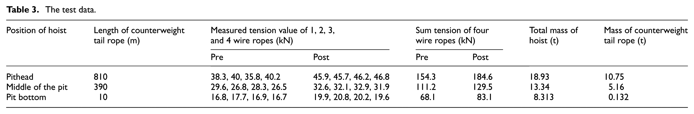
It can be seen from Table 3 that the pre- and post-compensation tension at pithead is 154.3 and 184.6 kN, respectively. The tension sum after compensation of four wire ropes is approximately equal to the total load of the hoist.
Conclusion and future work
When using the oil pressure sensors to measure the tension and load of wire ropes, the friction caused by piston moving in hydraulic connection device and the pressure loss caused by oil flowing in hydraulic pipe affect the accuracy of measurement results. To minimize the impact of friction and pressure loss, a mathematical model of hydraulic connection system is established in this article. The relevant parameters of the LuGre friction model are determined by hydraulic cylinder friction test, and the total pressure loss can be calculated by the formulas of the pressure loss along the pipeline and local pressure loss. Therefore, the friction and pressure compensation in the working process of hydraulic connection device are achieved. Finally, a monitoring system is designed and the real-time compensation test is carried out. The results show that the compensation improves the measurement accuracy of wire rope tension and load, which is of great significance for ensuring the safety of mine hoist.
In future studies, the authors will plan to further optimize the friction compensation model. Meanwhile, to obtain more accurate measurement results of the wire rope tension, the pressure sensor with the function of filtering and vibration reduction used in the tension conversion pressure method will be studied and designed.
Footnotes
Acknowledgements
The authors are grateful to the anonymous referees for their valuable comments and suggestions for improving the presentation of this paper.
Handling Editor: Xiaoxiao Han
Authors’ Note
Gaoyang Lei is also affiliated with Electrical and Mechanical Management Department of Yimei Group, Henan Energy and Chemical Industry Group Co. Ltd, Yima 472300, China.
Declaration of conflicting interests
The author(s) declared no potential conflicts of interest with respect to the research, authorship, and/or publication of this article.
Funding
The author(s) disclosed receipt of the following financial support for the research, authorship, and/or publication of this article: This research was funded by the University-Industry Cooperation Research Project in Jiangsu Province (grant no. BY2016026-02), the Priority Academic Program Development (PAPD) of Jiangsu Higher Education Institutions, and the State Key Laboratory of Integrated Services Networks (grant no. ISN10-10).