
Abstract
Master node delay is an unavoidable factor in a networked control system (NCS), which will lead to performance deterioration of the system, and large delay may even cause instability. In order to measure the master node delay in NCSs, its influence factors are analyzed and a non-perturbative black-box measurement method is proposed. In this method, a FPGA-based (Field-Programmable Gate Array) measurement device is developed, which sends out testing frames to master node periodically and triggers the master node to send out a response frame for every testing frame. Then the measurement device can get the measurement delay value by calculating the time interval between sending the testing frame and receiving the response frame, which consists of master node delay and some other delay that can be calculated precisely. Therefore, the accurate master node delay can be obtained by further processing the measurement delay value. A set of experiments were carried out and the results show that the proposed method can effectively measure the master node delay without a thorough understanding about its hardware and operating system software, and is not constrained by the type of operating system. Besides, as the master node delay can be measured exactly in the actual working condition without perturbing its user program by using this method, the results can reflect the real-time performance of the master node accurately. So that, it can provide a direct reference for choosing an appropriate master node for NCSs.
Introduction
Networked control system (NCS) is a kind of spatially distributed system wherein the control loop is closed through communication network. 1 NCSs can break the limit of point-to-point control and achieve remote operations, which makes it possible to design large-scale systems. 2 Compared to conventional control systems, NCSs have advantages in low cost of installation, flexibility in system implementation, ease of maintenance, efficient resource allocation and so on. However, the network delay is inevitable when control and status data are exchanged between master and slave nodes, which will degrade the performance of control systems and even cause system instability. 3
There are two main types of network delay in a NCS.
4
One is commonly called the network-induced delay, which can be divided into the propagation delay through the network medium and the transmission delay of the packets bits from the queue and into the link. The other is the processing delay of each component in NCSs due to its limited processing speed, such as the master node delay. Figure 1 shows a typical NCS model with the network delay.
5
Where, τ
sc
refers to the Block diagram of a discrete-time model of NCS.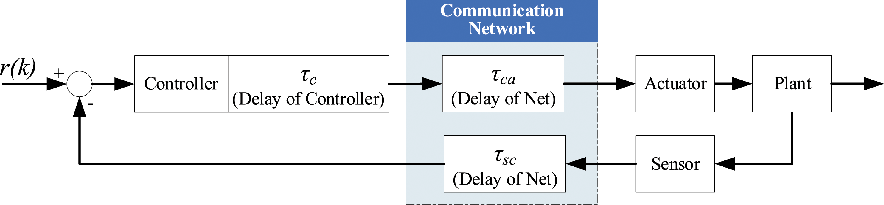
In traditional communication networks which are not real-time, the network-induced delay is much larger than the master node delay because of the data collision, transmission rate and so on. As a result, the previous literature, whether review articles, or research papers about the stability of NCS, 3,6 linear system, 7 nonlinear system 8 and software defined network real-time system, 9 mainly focused on τ sc and τ ca .
However, data collision of real-time Ethernet (RTE), such as EtherCAT, PROFINET IRT, Ethernet Powerlink, etc. Can be avoided, 10,11 and their bandwidth is as high as 100Mbps or even 1000Mbps, so the network-induced delay τ sc and τ ca have been greatly reduced. Besides, these delays can be calculated accurately based on the frame length and network topology. Some works 12-15 about the performance comparison of different RTEs provided the calculation methods of the minimum communication cycle of mainstream RTEs in common scenarios.
In fact, standard personal computer (PC) with real-time operating system (RTOS) as the master node is becoming more and more popular for its high computing ability, powerful integrated development environment and friendly human-machine interaction. For example, Windows operating system, equipped with a real-time extension software such as TwinCAT, 16 Codesys 17 or Kithara, 18 is competent to be the master node of a NCS. As the RTOS on standard PC is responsible for multi task, the master node delay is inevitable, and even larger than the network-induced delay. Hence, the master node delay τ c will account for an increasing proportion of network delay. Master node delay will affect the minimum communication cycle, dynamic performance and stability of NCSs, so analysis and measurement of the master node delay is needed, and a convenient and effective measurement method for the master node delay is proposed in this paper.
The paper is organized as follows. In Section 2, the factors causing the delay of PC-based master node are analyzed. Section 3 introduces the details of the proposed measurement method. Then, the development of the measurement device is given in Section 4. Section 5 is a set of experiments which give a performance comparison of different master nodes. At last, a conclusion is presented in Section 6.
Analysis for master node delay
The master node usually works as the controller in NCSs, while the sensors and actuators are all slave nodes. Hence, the master node delay should be the duration between the master node receiving an upstream status frame and sending out a downstream control frame.
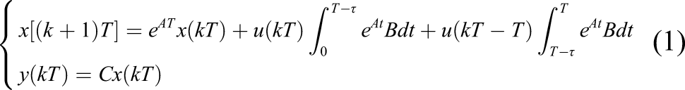
As shown in Figure 2, the master node delay is determined by both hardware and software, of which hardware delay is influenced by both CPU architecture and Design of motherboards and software delay includes operating system (OS) delay and algorithms efficiency. The OS delay can be further divided into Interrupt delay, Preemption delay, Task switching delay, Signal alternating delay, Deadlock release delay and so on. Factors of master node delay in NCS.
There are software and hardware methods for measuring OS delay. The software methods mainly employ code instrumentation 19 or embedded software testing tool. 20 The accuracy of these methods is not very high, because the operating system computational resources are occupied by both application program and testing software, and the precision of system clock is limited. Besides, a thorough understanding on OS principles is vital to modify system-level code.
The hardware methods 21-23 usually employ a signal generator to trigger the master node under test to produce a single output, and then an oscilloscope is used to measure the response delay between the input and output signals. Although the measurement result of hardware method is more accurate than that of software, it is not convenient for statistical analysis and long-term measurement.
However, all the methods above measure the real-time performance factors separately, and the actual delay of the master node is a combination of coupling factors. Besides, the master node delay caused by hardware is difficult to quantify independently. So it is difficult to obtain accurate master node delay with a white-box measurement method, and a non-perturbative black-box measurement method is proposed in this paper.
Measurement method for the master node delay time
In order to make the measurement result close to the actual working condition as more as possible, a NCS with master-slave structure is adopted, as shown in Figure 3. Where, a standard PC with RTOS or non RTOS works as master node under the test, and the measurement device based on FPGA works as a slave node. The measurement process is implemented in a FPGA chip, where high-speed clock and hardware solution can ensure the accuracy of measurement results. Overall schematic of measurement method.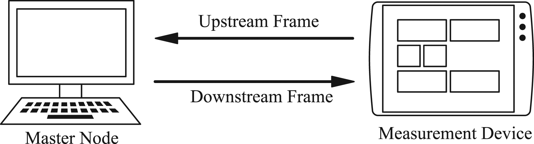
The proposed measurement method regards the master node as a black box, and the measurement device periodically sends upstream frames to the master node and receives the downstream response frames. At the same time, a high-precision timer designed in the FPGA records the sending and receiving time, so that the master node delay can be calculated. Acting as a trigger event, receiving an upstream frame makes the master node to implement data reception, data analysis, computational algorithm, downstream frame sending, etc. The whole process not only involves the delays caused by OS and computational algorithm, but also includes hardware factors. As a result, the master node delay of each communication cycle can be measured with high precision. Besides, the proposed method does not require any extra underlying system operation, which greatly reduces the difficulty of measurement and can be easily used in different types of OS.
Measurement Process
As shown in Figure 4, T
measure_k-1
and T
measure_k
denote the measurement delay of cycle k-1 and cycle k, respectively. T
master_k-1
and T
master_k
denote the master node delay of cycle k-1 and cycle k, respectively. T
cycle
denotes the communication cycle. The measurement process is shown in Figure 5. A detailed description of the measurement process is is as follows: a. At the beginning, set T
cycle
as the communication cycle of this time of measurement and set T
measure_0
as the initial value 0 which will not affect the statistical results. Then the master node is responsible for initializing the communication. b. After initialization, the measurement device switches to cycle communication state. In this stage, the measurement device will send an upstream frame with the measurement result of last communication cycle T
measure_k-1
cyclically according to the set period, and start an internal high-precision timer when sending out the upstream frame. c. After receiving the upstream frame, the master node parses T
measure_k-1
, calculates the master node delay T
master_k-1
, and writes the value into a file for further analysis. At the same time, the master node sends a downstream frame to the measurement device to response the upstream frame. d. The measurement device parses the received downstream frame online, and latches its internal high precision timer at the time of receiving the downstream frame. So that the measurement delay T
measure_k
of this cycle can be obtained. e. Repeat steps (b) – (d) to collect sufficient data for statistical analysis. Sequence diagram of measurement process. Measurement process.
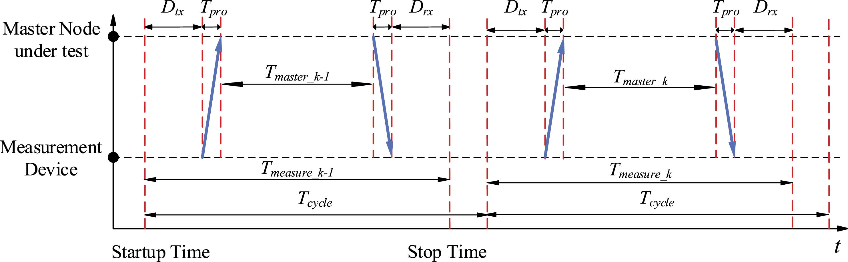
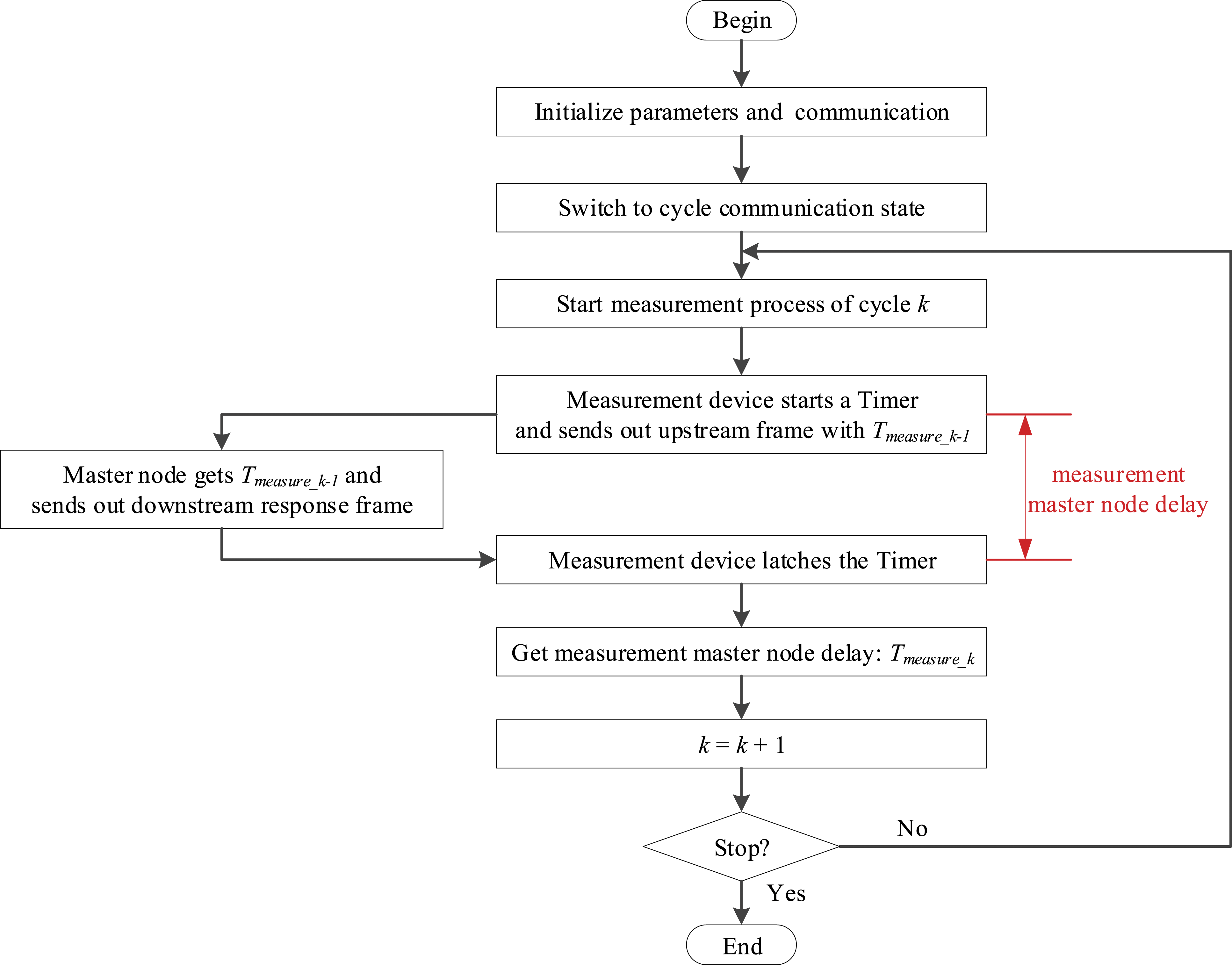
This method is mainly aimed at standard PC-based master node, which has powerful computing capability. Therefore, the measurement results are transmitted to the master node for subsequent calculation and data statistics just as step (c) shown.
The master node delay algorithm
The direct measurement result T
measure_k
contains the propagation delay, transmission delay and the device delay of the slave node, so subsequent operation is needed to calculate the exact master node delay, that is, the master node delay algorithm shown in Figure 6. Master node delay algorithm.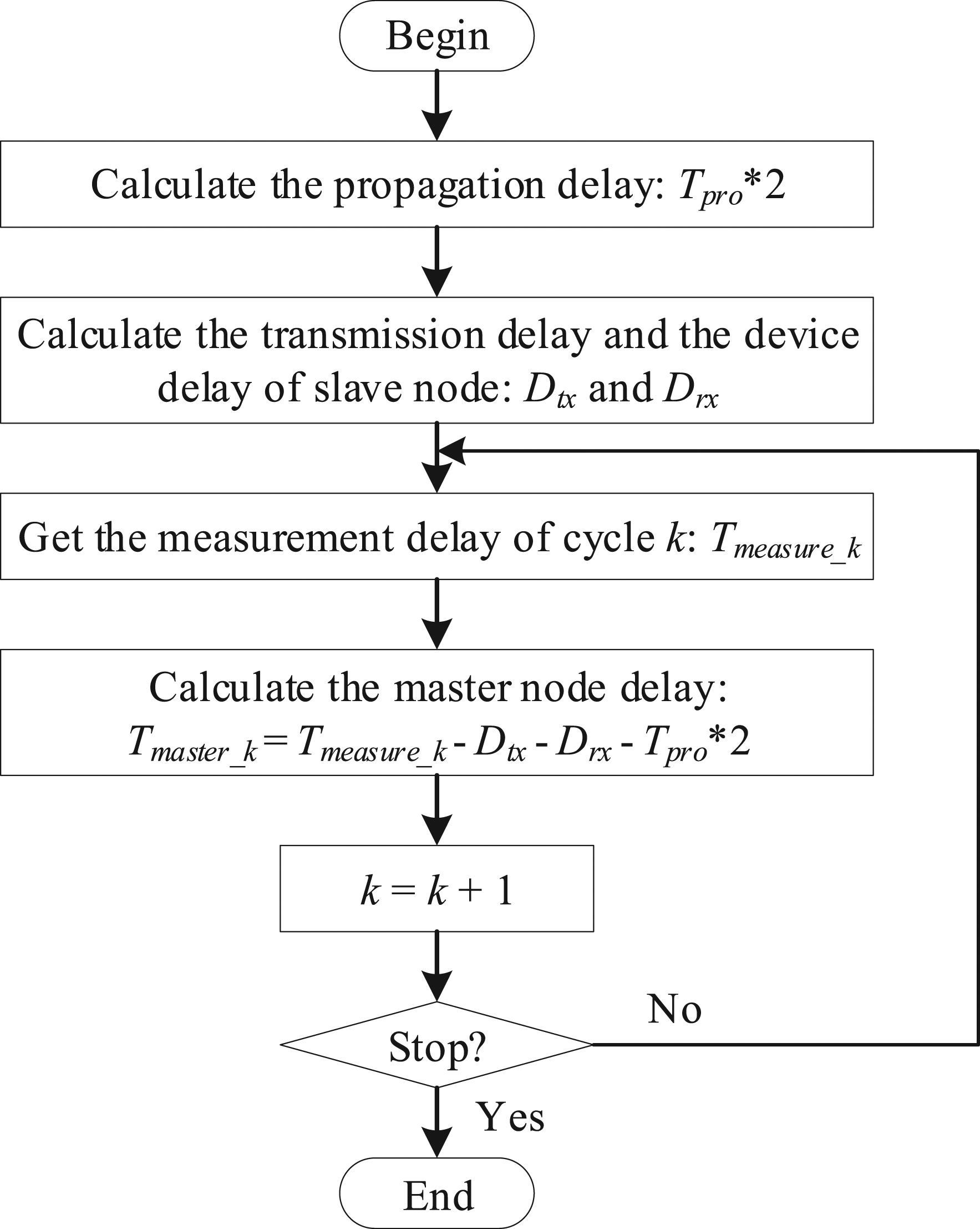
As shown in Figure 4, T
master_k
is the master node delay in cycle k

Where, T
measure_k
is the direct measurement delay time value measured by the measurement device in a communication cycle, which will be encapsulated into the upstream frame and sent to the master node. T
pro
is the time delay caused by the propagation of data frames over the network, which is mainly related to the length of the network cable L
cable
. The propagation delay is 4.8∼5.3 ns/m for category 5 cable. Then

D
tx
and D
rx
represent the delays caused by the measurement device when sending the upstream frame and receiving the downstream frame, respectively. The delays mainly consist of the delay of physical layer chip, D
PHY_tx
and D
PHY_rx
, and the delay of data frame transmission, T
frame_tx
and T
frame_rx
. Different physical layer chips have different D
PHY_tx
and D
PHY_rx
, which can be obtained from its datasheets or through experimental testing. Then


The network under test is the Fast Industrial Ethernet whose bandwidth is 100Mbps, so the transmitting rate is 80ns/byte. According to the frame structure of standard Ethernet shown in Figure 7, both upstream and downstream data frames take the Data and Pad region as the minimum value 46 bytes. Then, the length of data frame L
frame
and the delay of data frame transmission T
frame
can be obtained. Frame structure according to IEEE802.3.
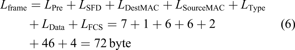
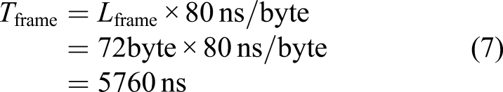
According to formula (4) – (7), both T
frame_tx
and T
frame_rx
can be calculated to be 5760ns, and the sum is 11,520ns. Besides, T
master_k
can be calculated by combining the formula (2) – (7).

Development of measurement device
The proposed measurement method in this paper adopts the master-slave structure. The slave node is developed based on a FPGA chip, whose hard real-time property can realize high precision measurement. For the master node, a program is necessary for standard PC with RTOS or non RTOS to response the frame from slave nodes.
Program Architecture of Master Node
The program running on master node is developed with C++, which consists of two parts: communication driver and control task program, as shown in Figure 8, communication driver and control task are two threads started by the master node. They cooperate with each other to implement the tasks of receiving and sending frames and processing measured values through events and semaphores. Program architecture of master node.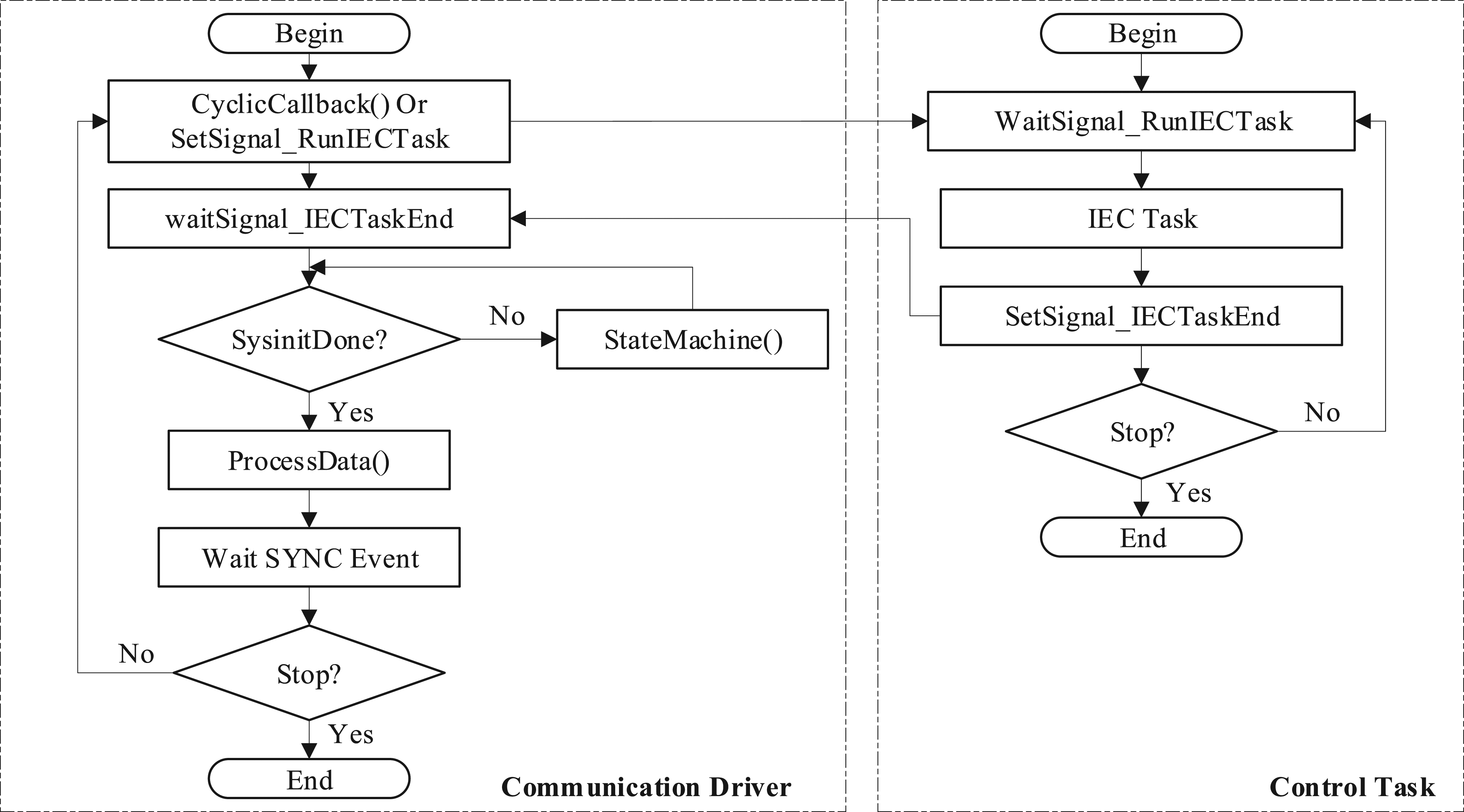
The control task is responsible for the parse of upstream frames, the storage of measured values and the packaging of downstream frames. In practice, all computational algorithms will be running on the master node under test, if which can be added to the program, the measurement results can be closer to the actual situation and more referential.
The communication driver is responsible for receiving and sending data frame, controlling of communication state machine and driving network card. In this part, communication function is realized by calling system API functions provided by RTOS employed by the master node under test. With this modular software design, the method can be implemented on different types of OS with only little extra work.
Development of measurement device node
The measurement device works as a slave node in NCSs, which is developed based on a FPGA chip from Altera, whose advantages are hard real-time, flexible, high-speed and reconfigurable. The device not only acts as a slave node to communicate with the master node, but also can obtain nanosecond resolution results with the high-precision timer in FPGA. Besides, the Nios II soft core technology is used to facilitate the analysis of the downstream frame and the preparation of the upstream frame.
The module of the FPGA program is described in detail as shown in Figure 9: Design of FPGA module. a. High precision timer in the Delay measurement module will be started when FPGA sends an upstream frame and latched when FPGA receives a response downstream frame from master node. The value of the timer will be sent to Nios II CPU. b. Nios II CPU encapsulates the Delay value into upstream frame when its value is updated cyclically. c. Cycle load module generates a signal with a set time interval to trigger the Uptransfer module to send upstream frame with the measured value to master node.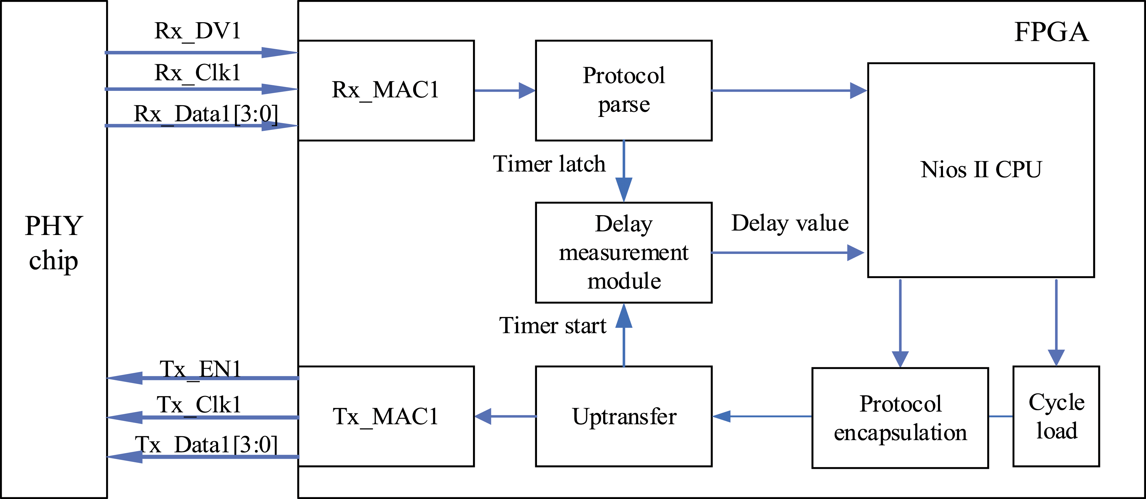
Experiment
In order to verify the proposed method, a set of experiments are designed to compare the master node delay of three different RTOSs (Windows 7 + Kithara, Windows CE 6.0 and Linux with RT-PREEMPT patch). Besides, a master node with Windows 7 is adopted as a reference for conventional non-real-time operating system. At the same time, industrial personal computer (IPC) and laptop are employed to compare the influence of hardware platform on the master node delay.
Experimental environment building
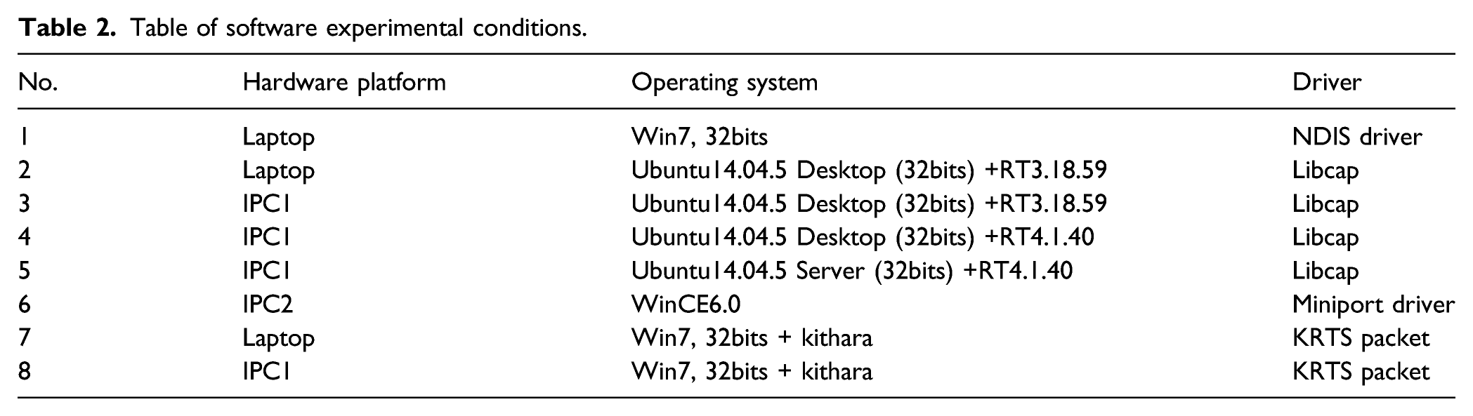
As shown in Figure 10, the hardware platforms of the master nodes are two IPCs and one laptop Thinkpad E430C (abbreviated as IPC1, IPC2, laptop) whose hardware information is shown in Table 1. Experimental environment. Hardware information of master node.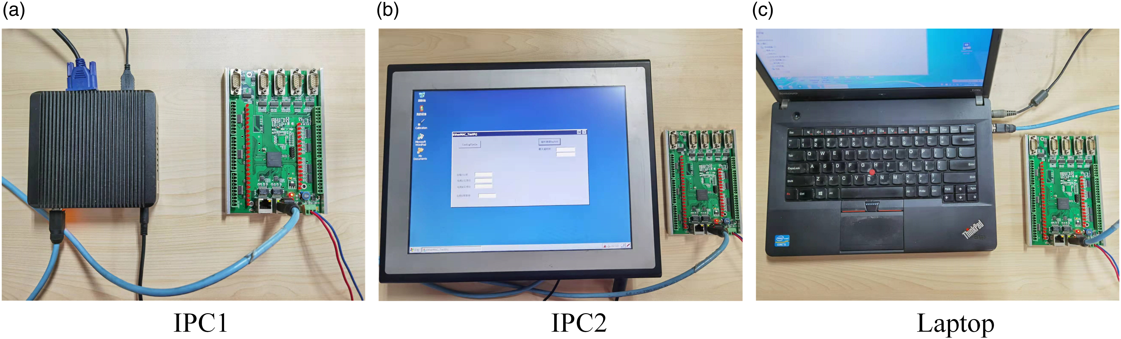
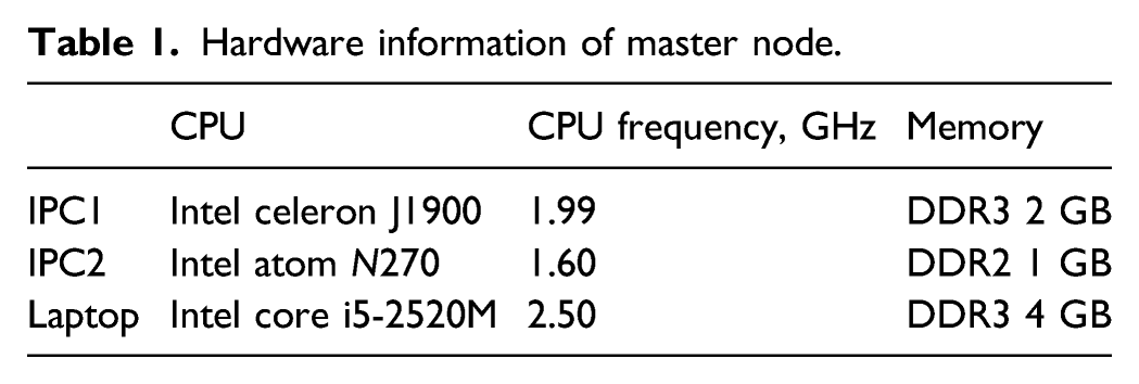
Table of software experimental conditions.
Some cross-comparison of the measurement results on these platforms are provided to show the measuring performance of the proposed method.
The right side of each image in Figure 10 is the measurement device, whose FPGA chip is EP4CE10F17C8N from Altera and PHY chip is LAN8710A from SMSC. According to LAN8710A’s datasheet, the total sending and receiving delay of LAN8710A is 320ns.
The master nodes under test are connected to the measurement device with a CAT-5 cable, and the cable length L cable is 1m.
T
master_k
can be calculated with formula (8).
Eight different experimental conditions as shown in Table 2 were established, and each measurement lasted for about 40 min with the communication period of 4 milliseconds. There are about 600,000 delay values collected for every time of measurement.
Analysis of experimental results
The histograms of these eight measurements results are shown in Figure 11. The X-axis is the value of the master node delay and the Y-axis is the percentage. Because there are lots of uncertain factors for master node delay, so the tested results are random, which may be particularly high for the poor real-time performance. As a result, the master node delay is widely distributed on the X-axis. There are always some long-time delays of small proportion in the overall sample, which results in a big blank on the right side of the original diagram. Thus, in order to show the results clearly, the data-intensive distribution areas are intercepted in Figure 11. Histogram of experiments data.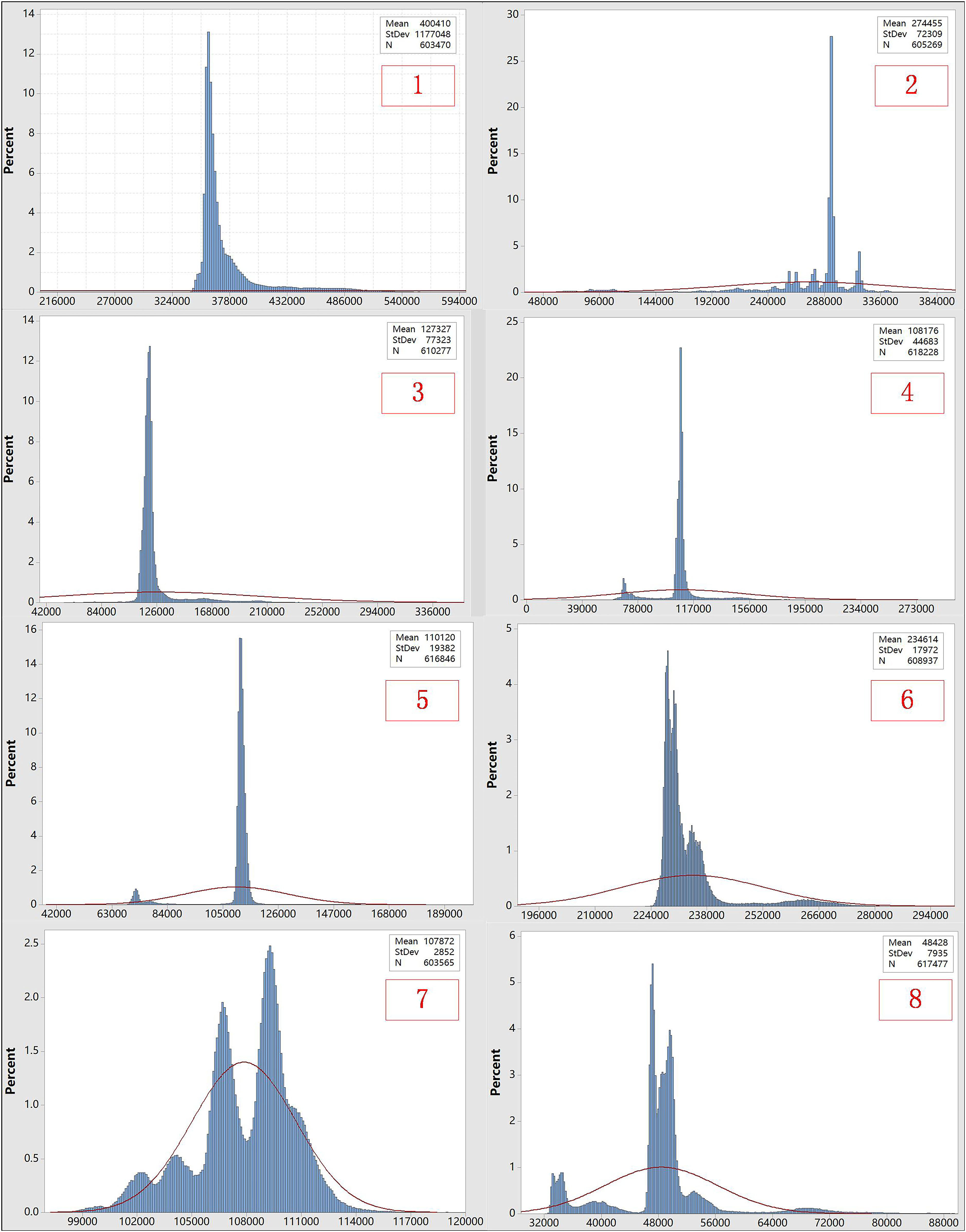
Statistic of experiments data.
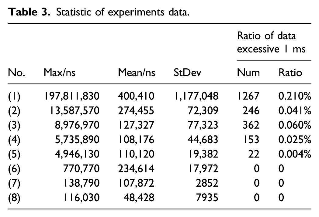
For Windows 7, the maximum delay is about 200 ms and the values are scattered, which means it cannot meet the real-time requirement for a master node in NCSs.
For RT Ubuntu with a RT-PREEMPT patch, the maximum delay is much smaller than Windows 7. However, it is still in millisecond level and the jitter is high. It is supposed the communication driver reduces its real-time performance, which limits the minimum communication cycle.
For WinCE 6.0, although the mean delay is larger than RT Ubuntu, its maximum is about 700 microseconds, which is better and conforms to the actual situation.
For Windows + Kithara, the maximum delay is about 100 microseconds, which has the best real-time performance. The standard deviation is much smaller than other OSs, which means the jitter of Windows + Kithara is also the best.
In addition, (2), (3) and (7), (8) in Figure 11 can also show the influence of hardware platform to the master node delay.
Conclusions
In NCSs, master node delay is inevitable, especially for the PC-based control system. This study analyzed the factors lead to the master node delay in NCSs, and proposed a non-perturbative black-box measurement method. As the delay measurement is implemented on a FPGA-based slave node, the master node can be tested without perturbation and all the complex factors of master node are consisted in the measured value as a black box, so that high accuracy can be achieved.
A set of experiments have been conducted, where different master nodes with different OSs were employed to verify the proposed method. And a cross-comparison of the measurement results have been concluded. Therefore, besides the master node delay measurement method, this paper also gives a reference for selecting an appropriate master node of NCSs.
Footnotes
Declaration of conflicting interests
The author(s) declared no potential conflicts of interest with respect to the research, authorship, and/or publication of this article.
Funding
The author(s) disclosed receipt of the following financial support for the research, authorship, and/or publication of this article: This work was supported by the National Key R&D Program of China under Grant 2019YFB2006200.