
Abstract
This study proposed a novel milling technology assisted by longitudinal–torsional compound ultrasonic vibration to overcome the difficulties in the processing of Ti-alloy heterogeneous surfaces or molding surfaces. Using the ball-end milling cutter as the research object, the geometrical model of the milling cutter edge was established, in which an axial position angle was used as the main parameter. The instantaneous cutting thickness was derived based on the cutter path and the cutting force model of the ball-head milling cutter under the longitudinal–torsional compound vibration condition. Finally, using the longitudinal–torsional synchronous vibration cutter system with a resonant frequency of 35.476 kHz and a longitudinal-to-torsional vibration amplitude ratio of approximately 0.25, the milling characteristics of fixed-curvature Ti-alloy workpieces under the longitudinal–torsional compound ultrasonic vibration condition were examined. Results show that the application of the longitudinal–torsional compound ultrasonic vibration can remarkably reduce the radial force Fx but impose almost no effects on the tangential force Fy and the axial force Fz.
Introduction
Due to a series of favorable material properties, titanium (Ti) alloys now have been widely applied in many high-tech fields mainly including weapon industry, aerospace, and medical equipment.1,2 The impeller blades of aero-engines are mainly made up of Ti alloys, which set extremely high requirements on parts processing quality. In particular, for Ti-alloy parts with heterogeneous surfaces or molding surfaces, surface quality can hardly be guaranteed when using a low-efficiency ordinary machining.3,4 In consideration of an excellent processing property and low equipment cost, an ultrasonic-assisted milling technology has become a new way of overcoming a lot of difficulties in surface machining of Ti alloys.5,6
Scholars all over the world performed a great deal of experimental and theoretical research of surface milling processes.7,8 In combination with virtual simulation results, H Sun 9 established the mathematical model of the dynamic cutting force of the ball-end milling cutter and the related dynamic model and also performed time-domain dynamic simulations of the milling process. Hiroyasu et al. focused on the surface cutting process by a ball-end milling cutter, explored the related cutting mechanism, and established geometrical models of the ball-end milling cutter and a concave surface. According to the calculation, the volume of the maximum cutting zone on the concave surface was 1.8 times greater than the volume of cuttings on the slope. 10 Accordingly, a novel trajectory planning method for annular cutters was proposed, whose effectiveness in controlling the formation of a cutting zone was also confirmed.
In recent years, due to the limitations of a single ultrasonic vibration cutting (UVC) mode in a milling process, some compound vibration modes mainly including the longitudinal–torsional vibration or longitudinal–flexural vibration have attracted much attention of many scholars.11–13 In terms of the compound vibration mode, S Lin 14 theoretically concluded that the longitudinal vibration and torsional vibration may have the same resonant frequency in the exponential-type ultrasonic horn. J Zheng et al. 15 designed a conical composite horn for realizing compound longitudinal–torsional vibration, theoretically calculated the size parameters of the longitudinal–torsional horn, and also conducted the related tests for validation. Using a traditional analytical method, J Tang et al. 16 designed a conical transitional ladder longitudinal–torsional compound ultrasonic vibration horn at the same frequency and employed ANSYS simulations for validation. Regarding an application of the compound vibration, Y Wantanabe et al. applied the longitudinal–torsional compound ultrasonic vibration technique to an ultrasonic motor;17,18 J Han 19 applied the longitudinal–torsional compound ultrasonic vibration technique to a surface treatment technique; Pi and Xu 20 used the longitudinal–torsional ultrasonic vibration technique in a milling process and experimentally found that the longitudinal–torsional ultrasonic milling can enhance both the processing efficiency and the quality of processed surfaces. Based on the self-developed longitudinal–torsional resonance ultrasonic cutter system, this study established an experimental platform on DMG80 processing center; then, the instantaneous thickness of cuttings was calculated based on the tool path and the cutting force model of the ball-end milling cutter under longitudinal–torsional compound vibration conditions; finally, the longitudinal–torsional milling resonant ultrasonic millings were performed on the constant-curvature Ti-alloy surface workpieces to validate the effectiveness of the proposed milling method at high-quality and high-efficiency processing of Ti-alloy surface workpieces.
Analysis of the cutting force of the ball-end milling cutter
Design of the cutting edge of the ball-end milling cutter
During the milling process, undeformed cuttings are distributed along the cutting edge and the cutting thickness changes with the position of the infinitesimal tool point angle. In the designed milling model, the infinitesimal dynamic angle of the cutting edge is a vector, and the cutter performs the cutting motion clockwise. Therefore, the clockwise direction was used as the positive direction of the angle. Figure 1 displays the constant-lead spherical helix.
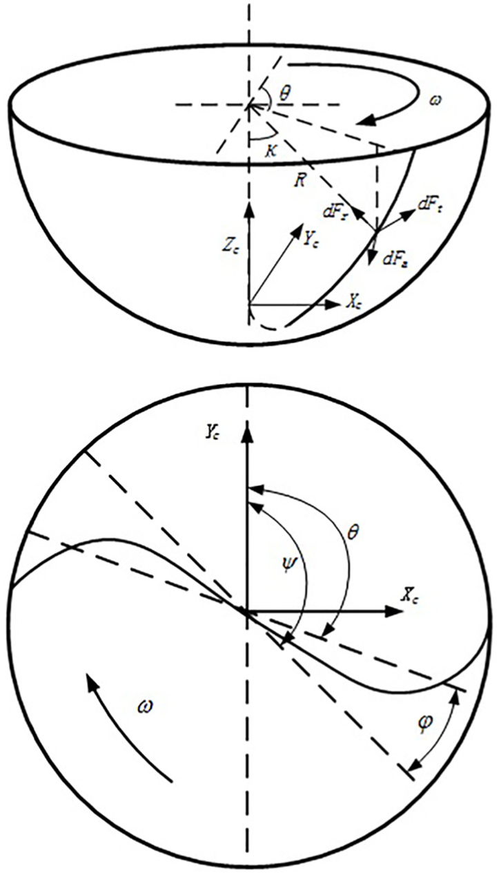
Spiral cutting edge for ball end mill.
In Figure 1, R is the radius of the ball-end cutter, K is the axial position angle of the unit cutting edge, θ is the position angle of the unit cutting edge, Ψ is the position angle of the cutting edge, and
Using the axial position angle of the unit cutting edge as the parameter, the curve of the cutting edge can be described as

The lag helical angle can thus be written as

where Ψj denotes the position angle of the jth cutting edge, m is the number of cutter teeth, and α is the nominal helix angle.
The vector of the cutting edge curve can be written as

The infinitesimal length of the cutting edge can thus be written as

The thickness of the infinitesimal cuttings can be calculated as

Establishment of the cutting force model of the ball-end milling cutter for ordinary milling processing
The mechanical linear infinitesimal cutting force model proposed by Armarego and Epp 21 was used for the modeling of the cutting force of a ball-end cutter, and the thickness model of undeformed cuttings with horizontal feed by the ball-end milling cutter proposed by Lee and Altintas 22 was used to model the thickness of undeformed cuttings. The mechanical modeling assumes that a certain proportional relation exists between the infinitesimal cutting force and the thickness of instantaneous undeformed cuttings. The proportional relation is also referred to the coefficient of the cutting force.
The infinitesimal cutting force model can be written as

The thickness of undeformed cuttings can be written as

where dS and db are the infinitesimal length of the cutting edge and the infinitesimal width of undeformed cuttings, respectively; Kte, Kre, and Kae denote the cutting coefficients of the plowing force on the unit cutting edge along the tangential direction, radial direction, and binormal direction, respectively; Ktc, Krc, and Kac denote coefficients of the shear force on the unit cutting edge along the tangential direction, radial direction, and binormal direction, respectively; tn and tx are the thickness of the cuttings and feed per tooth, respectively; K and θ denote the horizontal position of the unit cutting edge; Ψj denotes the position angle of the jth cutting edge; Kup and Klow denote the K angles corresponding to the cut-in and cut-out of the cutting edge, respectively.
Ball-end milling cutters are mainly used for the machining of complex surfaces. For simplifying the analysis process, this study used the slope with an infinite curvature radius to represent the surface and solve Kup and Klow.
As shown in Figure 2, K denotes the slope angle, and K0 denotes the value of K corresponding to the maximum cutting depth


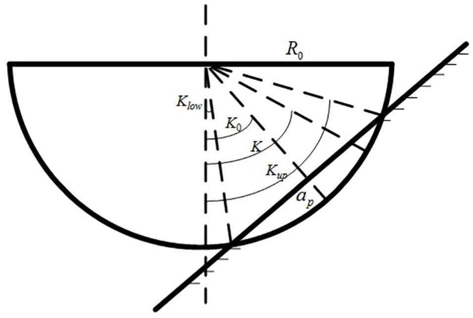
Diagram of axial position angle.
By substituting equations (1)–(5) and (7) into equation (6) and performing the coordinate transformation, the projection of the unit cutting edge in the coordinate system of the cutter can be written as

By integrating the infinitesimal cutting force, the overall cutting force can be calculated as


Table 1 lists the settings of technological parameters. The waveform of the cutting force was then plotted using MATLAB, as shown in Figure 3.
Parameters in simulation of cutting force.

Simulation of cutting force.
Effect of the longitudinal–torsional compound vibration on the cutting force model
An essential difference between ultrasonic milling and traditional milling is that the former is a kind of high-frequency interrupted cutting. During longitudinal–torsional compound ultrasonic milling, with regard to the longitudinal vibration, when its amplitude is less the cutting depth, the cutting tool is always tangent to the workpiece and the cutting force is equivalent to the sum of the high-frequency oscillating signal and the ordinary cutting force signal; as regard to the torsional vibration, when the cutting velocity of the milling cutter
Figure 4 shows the projection result on XOY plane, in which the black curve represents the position of the cutter tool at T0, the red curve represents the position of the cutter tool at (

Since

Torsional motion characteristics of cutter tip.
Based on the cutting force model, Ψj and K are the parameters that affect the thickness of undeformed cuttings. During the longitudinal–torsional compound ultrasonic milling, Ψj and K can be written as


where A1 and A2 denote torsional and longitudinal vibration amplitudes, respectively, and f is the vibrational frequency.
In equation (14), since
By substituting equations (14) and (15) into equation (12), an overall cutting force model under the longitudinal–torsional ultrasonic vibration can be derived as

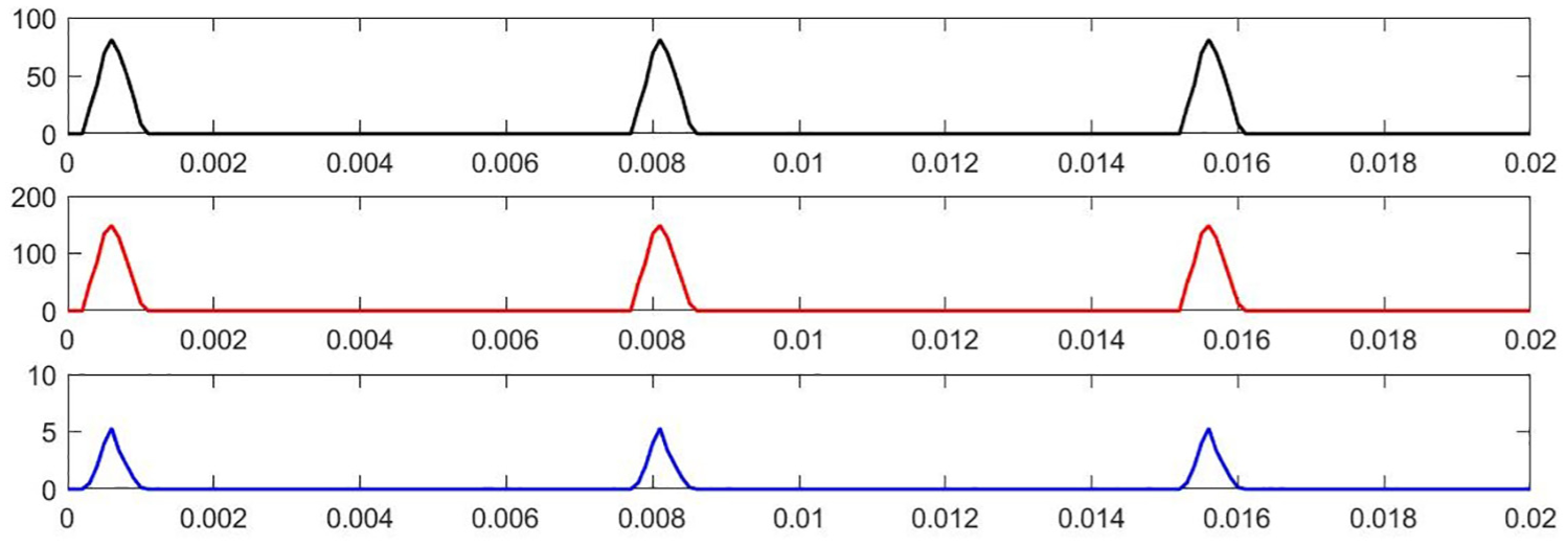
Table 2 lists the ultrasonic parameters. The waveform of the cutting force by a single tooth is plotted using MATLAB.
Parameters of ultrasonic vibration.

According to the simulation results of the cutting force waveform shown in Figure 5, when the cutter cut a workpiece in the ultrasonic vibration milling process, the cutting force increases; under an action of the ultrasonic vibration, the cutter performs high-frequency cut-in and retard motions and the cutting force waveform is a high-frequency high-energy vibration signal.

Waveform of ultrasonic cutting force.
Experiment study
Experiment conditions
Table 3 lists the parameters of the used Ti-6A1-4V alloy. SGO55 ultra-fine-particle tungsten-steel ball-end milling cutter, with a diameter of 8 mm, was used, whose parameters are presented in Table 4. Figure 6 illustrates the developed longitudinal–torsional resonance ultrasonic milling system, in which the ultrasonic torsional vibration can be generated by a spiral groove on the amplitude-change horn. Using the PV70A impedance analyzer developed by Beijing Lianbangshidai Electronics Co., Ltd., the system’s resonant frequency was measured, as shown in Figure 7. The system’s resonant frequency was 35.476 kHz. The amplitudes were measured by the laser displacement sensor developed by KEYENCE Company. As shown in Figure 8, Point 1 and Point 2 were arranged for measuring the longitudinal–torsional vibration amplitudes of the ball-head cutter. Through the multiple measurements, the ratio of the longitudinal vibration amplitude to the torsional vibration amplitude of 0.25 was almost unchanged. Figure 9 shows the experimental set-up.
Chemical composition of Ti-6Al-4V alloy.

Geometrical parameters of cutting tool.


Model and simulation of optimized horn.
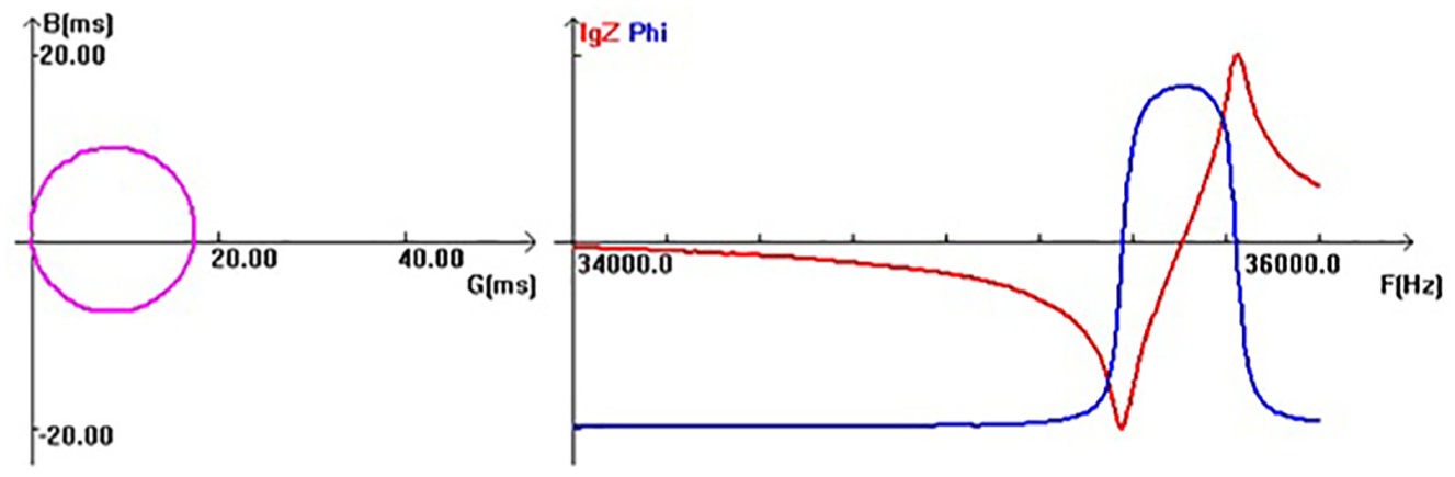
Impedance analysis of the horn.

Measuring ultrasonic amplitude.

The experimental devices.
Experiment results
Analysis of the cutting force
Figure 10(a)–(f) displays the measured and simulated cutting force waveforms when a single cutting edge cuts a workpiece using ordinary processing and ultrasonic processing, respectively. Table 5 lists the cutting force coefficient.

Waveform of cutting force (R = 30 mm, K = 15°, ap = 0.5 mm; fz = 0.05 mm/z; v = 20 m/min).
Cutting force coefficient. 23

It can be observed that during the ultrasonic vibration milling process, when the cutter cut a workpiece, the cutting force increases. Under an ultrasonic vibration action, the cutter performs high-frequency cut-in and retard motions, and the cutting force waveform is an addition of the high-frequency high-energy vibration signal to a smooth curve. Meanwhile, the exposing to ultrasound can remarkably reduce the radial force Fx, but impose slight effects on the variations of the tangential force Fy and the axial force Fz.
Comparing the cutting forces obtained under different cutting conditions as shown in Figure 10, it was found that all the cutting forces Fx, Fy, and Fz were decreased when processed by ultrasonic. That is, the simulation values of the radial force Fx, axial force Fy, and tangential force Fz were decreased by 58%, 19%, and 33%, respectively. Simultaneously, the measured values Fx, Fy, and Fz were decreased by 60%, 27.7%, and 33%.
Conclusion
First, by selecting the axial position angle as the main parameter, the geometrical model of the cutting edge of the ball-end milling cutter was designed; the instantaneous thickness of chippings was solved by the cutter path and then substituted into the mechanical linear cutting force model, and finally, the model of the cutting force of the ball-end milling cutter under the longitudinal–torsional compound vibration condition was derived.
An ultrasonic longitudinal–torsional vibration milling cutter system was designed and manufactured. According to the acoustic performance tests, the system’s resonant frequency was 35.476 kHz, and the ratio of the longitudinal vibration amplitude to the torsional vibration amplitude remained almost unchanged at approximately 0.25 value.
The processing characteristics of Ti-alloy surfaces using the longitudinal–torsional compound vibration ultrasonic milling process were investigated. According to the experimental results, the introduction of the ultrasonic vibration can remarkably reduce the radial force Fx, but impose slight effects on the variations of the tangential and axial forces Fy and Fz. The simulation values of the radial force Fx, axial force Fy, and tangential force Fz were decreased by 58%, 19%, and 33%, respectively. Simultaneously the measured values Fx, Fy, and Fz were decreased by 60%, 27.7%, and 33%, respectively.
Footnotes
Handling Editor: Xichun Luo
Declaration of conflicting interests
The author(s) declared no potential conflicts of interest with respect to the research, authorship, and/or publication of this article.
Funding
The author(s) disclosed receipt of the following financial support for the research, authorship, and/or publication of this article: This research was supported by National Natural Science Foundation of China (no. 51675164, no. U1604255, and no. 51875179).