
Abstract
The stability and free vibration analyses of single and double composite Timoshenko beams have been investigated. The closed-section beams are subjected to constant axially compressive or tensile forces. The double beams are assumed to be connected by a layer of elastic translational and rotational springs. The coupled governing partial differential equations of motion are discretized, and the resulted eigenvalue problem is solved numerically by applying the Chebyshev spectral collocation method. The effects of the elastic layer parameters, the axial forces, the slenderness ratio, the bending–torsional coupling, and the boundary conditions on the critical buckling loads, mode shapes, and natural transverse frequencies have been studied. A parametric study was performed, and the obtained results revealed different features, which hopefully can be useful for single- and double-beam-like engineering structures.
Keywords
Introduction
Beam-type structures are basic components of several applications in the mechanical and aerospace engineering disciplines and are commonly used in constructions and structural systems. Understanding the different characteristics of the structures is crucial to ensure a good performance and to avoid failure. For example, determining the natural frequencies of a structure is important to avoid resonance. Moreover, estimating the critical buckling loads is essential to prevent instability and to help the designer in choosing an appropriate length and cross-sectional area of the beam to be used in such application.
Due to their high strength-to-weight ratio, high stiffness, and vibration absorption; double-beam systems are widely used in engineering applications such as sandwich or composite beams, multiple-walled carbon nanotubes, aircraft wing spars, tall building, double-beam cranes, railway tracks resting on elastic foundations, pipelines, bridge spans, and trusses. 1 In some applications, as the main beam is excited, passive vibration control could be achieved by suppressing the undesired vibration by the aid of the auxiliary (secondary) beam.2,3 Besides, the relative motion of the two beams could play an important role in dissipating the mechanical energy of the system.
Many researchers addressed the dynamic analysis of double-beam systems. For example, H Fei et al. 4 investigated the dynamic characteristics of a inclined and tensioned double-beam system. The two different beams are connected by elastic springs, and the governing equations of motion are derived by considering the effects of the flexural rigidity, sag, inclined angle, and the boundary conditions. The system was simplified into 4-degrees-of-freedom (DOF) system, and a semi-theoretical semi-numerical approach was proposed to solve the dynamical properties and the frequency equation of the structure. Furthermore, Murmu and Adhikari 5 presented the vibration analyses of coupled nanobeam system under initial compressive pre-stressed condition. Eringen’s nonlocal elasticity model was used to obtain the expressions for bending-vibration of the double-nanobeam-system. The nano-scale and coupling spring effects were examined, and it was shown that they have a significant influence on the natural frequencies of the nonlocal double-nanobeam-system. The results revealed that the nonlocal effects and the increase in the pre-stressed load tend to decrease the frequencies. In another study, Szmidt 6 experimentally and analytically carried out the dynamics of twin cantilever beams connected by a viscoelastic member, and the shear deformation was taken into consideration. A continuous system was introduced to identify the model by finding the stiffness and the damping properties of the free vibrations of a single cantilever beam excited in the first mode. The effect of the viscoelastic member on the vibration characteristics of the system was examined. Li et al. 7 discussed the free and forced vibration analysis of a double-beam system connected by a viscoelastic layer. A semi-analytical method was applied to find the natural frequencies and mode shapes. The forced vibration responses were obtained by utilizing a modal-expansion iterated method by deriving an orthogonality condition for the double-beam system to decouple the governing differential equations of motion. Moreover, KV Nguyen 8 studied the effect of a concentrated mass position on the free vibrations of a cracked double-beam system connected by an elastic layer. Numerical simulations were conducted, and it was shown that the frequency of the cracked double beam varies irregularly when the concentrated mass is located at the crack position, and the crack position can be detected by the location of peaks of the wavelet transform of the relationship between the natural frequency and the location of concentrated mass. Kelly and Srinivas 9 applied a normal mode solution to determine the natural frequencies and mode shapes for a set of Euler–Bernoulli beams subjected to axial loads and connected by continuous elastic layer. Mirzabeigy et al. 3 utilized the differential transform method to obtain the natural frequencies and the mode shapes of two parallel beams connected by a layer with a linear and parabolic variation. It was assumed that the ends of the beams were supported by translational and rotational springs. The influence of the stiffness layer, flexural rigidity of the beams, and the boundary conditions on the vibration characteristics was addressed. Oniszczuk 10 applied the classical Bernoulli–Fourier method to determine the natural frequencies of two parallel simply supported beams continuously joined by a Winkler elastic layer. Two partial differential equations (PDEs) were used to describe the motion of the system, and the initial-value problem was considered to find the natural frequencies and the mode shapes. In another study, Di Lorenzo et al. 11 carried out the study of flexural behavior of layered elastically connected Euler–Bernoulli beams. It was assumed that the beams were supported with translational and rotational springs (considered as supports and joints). The theory of generalized function was used to derive the exact beam modes for the systems with discontinuities associated with the supports and joints. By applying the pertinent orthogonality conditions, the time response was found using the linear superposition and the modal analyses.
Moreover, the effect of the compressive force on the dynamics of beams undergoing bending–torsional-coupled vibrations was investigated by Prokić and Lukić. 12 A closed-form solution of the equations of motion simply supported thin-walled beams was derived using Vlasov theory. The impact of axial force, bending–torsion coupling, rotary inertia, and warping stiffness on the behavior of thin-walled beams was demonstrated. In addition, Li et al. 13 applied the dynamic transfer matrix method to analyze the free vibration behavior of thin-walled Timoshenko beams subjected to axial loads. A continuous model was assumed, and the equations of motion for coupled bending and torsional vibration were obtained. A parametric study was carried out to determine the impacts of the axial compression force, warping stiffness, shear deformation, and rotary inertia on the frequencies and mode shapes of the Timoshenko beams.
In another study, J Li et al. 14 utilized the dynamic transfer matrix method to examine the free bending–torsional vibrations of axially loaded Euler–Bernoulli beams with thin-walled open monosymmetrical cross sections. The coupled vibration characteristics of axially loaded slender composite beams were investigated by J Li and X Jin. 15 The natural frequencies and mode shapes are obtained by solving the governing differential equations of motion. The normal mode method was used to obtain the displacement response of slender composite beams with solid and closed thin-walled cross sections.
Other articles addressed the mechanics of bending–torsional behavior of beams. For example, Vo and Lee 16 utilized the stationary value of total potential energy to examine the flexural behavior of composite box beams. The finite element method was applied to predict the deflection of thin-walled composite box beams acted upon by vertical and torsional loads. The effects of boundary conditions, laminate orientation, and span-to-height ratio of the composite beam on the vertical displacement and angle of twist were illustrated.
Also, Latalski et al. 17 discussed the free and forced vibrations of a rotating rigid hub and a flexible composite thin-walled beam. Hamilton’s principle is used to derive the PDEs of motion of the beam that is featuring bending-twist coupling. The influence of the hub mass, rotary inertia, and fiber lamination angle on the natural frequencies was considered. Sousa and Da Silva 18 carried out the behavior of multilayered composite beams with horizontal interlayer slip, where the displacements and slips were obtained after applying the boundary conditions. Kahya 19 presented the buckling response of laminated composite beams. The first-order shear deformation theory was utilized, and the finite element method was applied to obtain the critical buckling loads.
Based on the above review, it is noted that the free vibrations and the buckling characteristics of double composite Timoshenko beam systems were not investigated. In addition, in most cases, it was assumed that the elastic layer, that connects the beams, is a set of translational springs only. In this theoretical study, the free vibration and buckling behavior of double composite Timoshenko beam systems, connected with an elastic layer that consists of translational and rotational springs, are proposed. The double-beam system is featuring bending–torsion coupling, which is of particular interest from an aeroelastic point of view. The spectral Chebyshev collocation method is used to discretize the governing PDEs of motion and to convert them into a system of algebraic equations. Then, the resulted eigenvalue problem is solved to determine the natural frequencies, mode shapes, and the critical buckling loads of the double-beam systems under consideration.
Mathematical model of a single and double composite Timoshenko beams
In order to obtain the governing equations of motion of a single straight beam subjected to axial compressive force, and featuring coupled bending–torsional vibrations, Hamilton’s principle will be utilized. The total potential energy, U and the kinetic energy, T of the axially loaded composite Timoshenko beam are given as
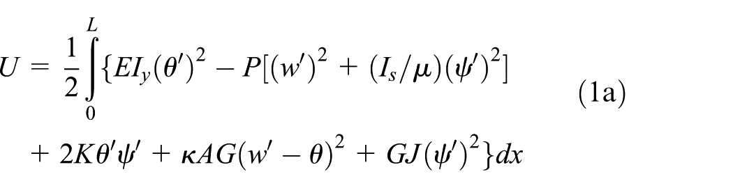

where ρ is the density of the material, E is Young’s modulus,
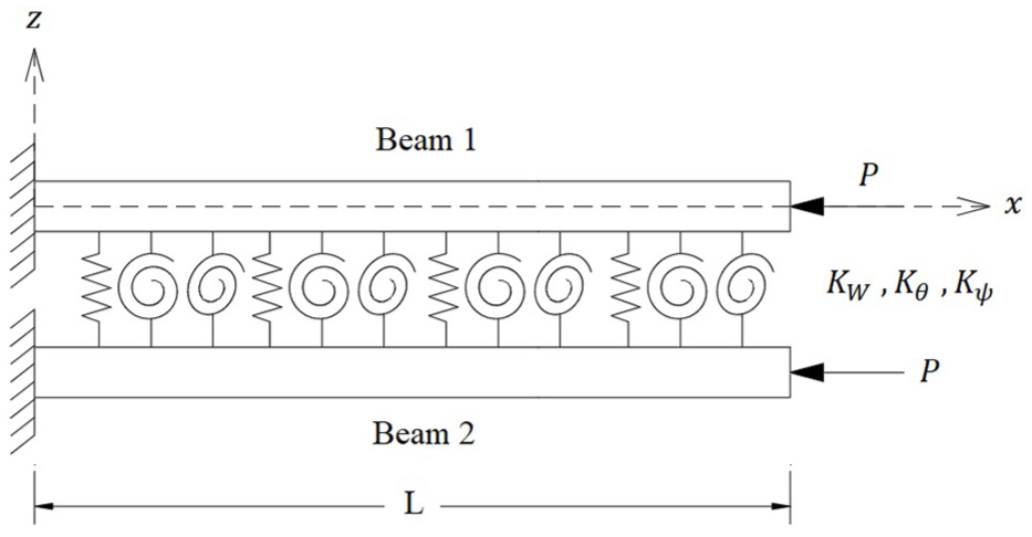
The double composite Timoshenko beam system under consideration.
Hamilton’s principle is applied to obtain the governing equations of motion and the boundary conditions

where W is the virtual work done by the nonconservative forces, which is set to zero in this study. Substituting equations (1a) and (1b) into equation (2), and setting


Due to the symmetry in the xz and xy planes, and as the x-axis is the locus of the shear centers, only the ply orientation causes the bending–torsional vibrational coupling. The equations were derived previously in Kaya and Ozgumus 20 and repeated in this study for convenience. Assuming harmonic solutions in time as


where

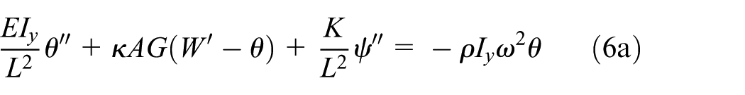
Substituting equations (4a)–(4c) and (5) into equation (3a)–(3c) yields


In this study, two types of boundary conditions, free (F) and clamped (C) are considered. For a clamped edge, the displacements W, θ, and ψ equal zero; whereas for a free edge, the bending moment, shear force, and the torque equal to zero, and they are given as: 20
Bending moment

Shear force

Torque

For the double-beam system, equations (4a) and (4b) can be applied to each of the beams that are connected by a continuous elastic layer (that consists of linear translational and rotational springs) shown in Figure 1. Assuming that the beams are identical (have the same material properties), the governing equations of motion are given as


where Kθ and Kψ are the stiffnesses of the rotational springs that resist the rotation around the z and x axes, respectively, and KW is the translational stiffness of the spring that resists the translation in the z-axis. It is assumed that the stiffnesses of the translational/rotational springs are independent of the material properties of the beams.
Solution procedure: Chebyshev collocation method
When performing analysis on single and double composite Timoshenko beam undergoing coupled bending–torsion coupling, it becomes challenging to obtain a closed-form solution to the vibration and buckling problems for these systems. Hence, the Chebyshev spectral collocation method is utilized for numerical solutions. Gauss–Chebyshev–Lobatto or Chebyshev collocation points are defined as the projections of equally spaced segments on the upper half of the unit circle on the interval [–1, 1]. These points are numbered from right to left, and are defined as 21

The Chebyshev differentiation matrix,

In this study, the X axis is normalized to be in the range of [0, 1]; thus, the Chebyshev differentiation matrices will have different entries than those obtained by Trefethen21 as they depend on the distribution of the points. Due to its accuracy, fast convergence, and simplicity in implementation, the Chebyshev spectral collocation method has effectively been utilized to carry out the free vibration and buckling analyses of one, two, and three-dimensional continuous systems (at the macro- and micro-levels).22–24 When discretizing ordinary differential equations (ODEs) and PDEs by the Chebyshev collocation method, the nth derivative of a function is represented by Dn = (DN) n . According to the Timoshenko beam model under consideration, each Chebyshev point possesses 3 DOFs—θ, Ψ, and W. Hence, a displacement vector is defined as

where N + 1 is the number of points in the X direction (along the beam’s span); θ1, Ψ1, and W1 are the displacements at X = 0, and θN
+
1, ΨN
+
1, and WN
+
1 are the displacements at X = 1. The size of the vector {U} is

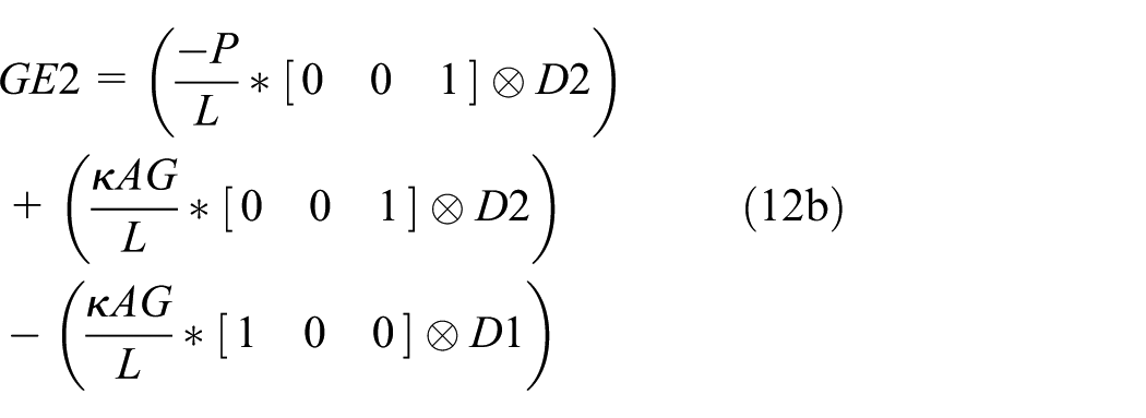

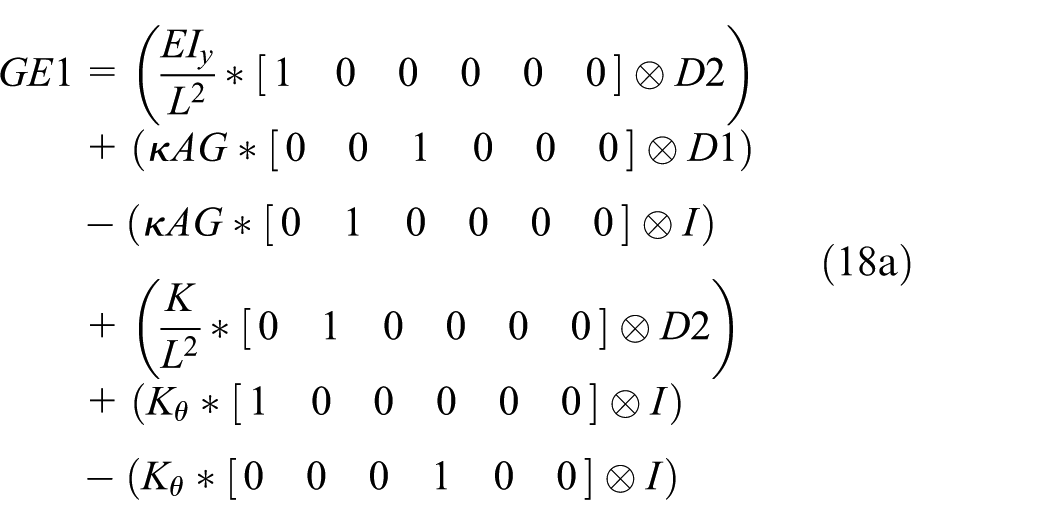
In a similar manner, the right-hand sides of equations (6a)–(6c) are discretized as


The whole system of equations is put in matrix vector form as
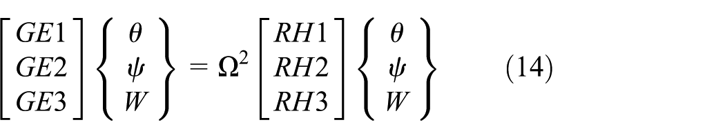
The size of each term (GE1, GE2, GE3, RH1, RH2, and RH3) is
Clamped (C)


Free (F)


where
For the double-beam system, the displacement vector is defined as
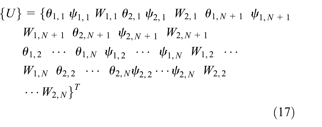
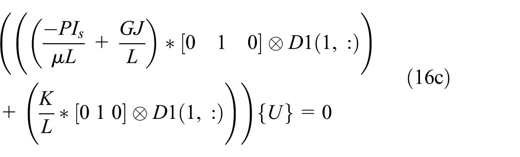
where the first subscript refers to the ith beam (beam 1 or beam 2), and the second subscript refers to the jth Chebyshev point along the beam’s span (j = 1, 2, …, N + 1). The governing equations (8a)–(8f) are discretized as
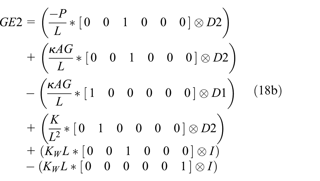

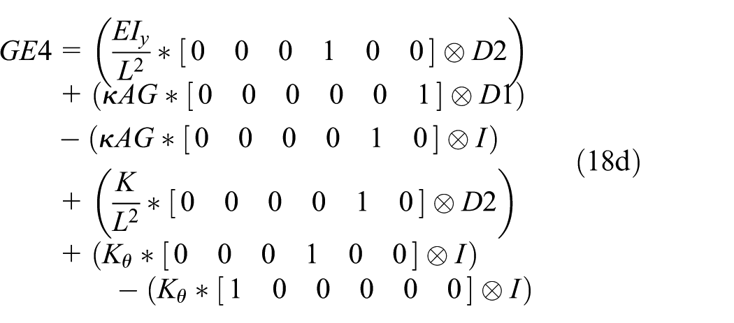

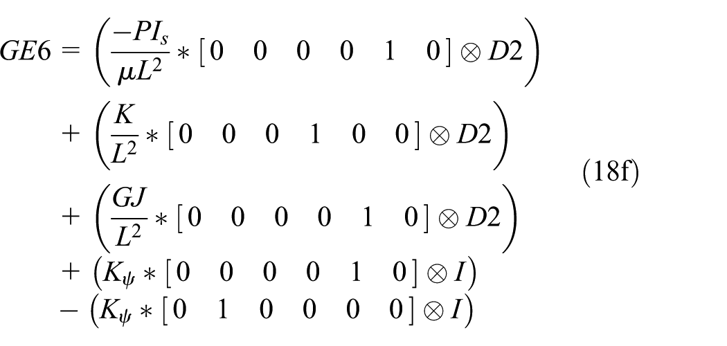
The right-hand side of the governing equations and the boundary conditions are discretized following the same scheme. Once the boundary conditions are applied, the system (single or double beam) is written as

where the subscripts B and I indicate the grid points used for writing the collocation analog of the boundary conditions and the governing differential equation, respectively. For the single beam, the size of
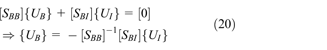
Substituting equation (20) into equation (19) yields the final eigenvalue equation as

The natural frequencies are obtained by calculating the eigenvalues of the matrix

Results and discussion
A glass–epoxy composite beam with a rectangular cross section is used in the analysis, and it is assumed that the beam has unidirectional plies with fiber angles of 15°. The beam has the following properties (unless otherwise stated): 20 width = 12.7 mm, thickness = 3.18 mm, EI = 0.2865 N m2, GJ = 0.1891 N m2, kAG = 6343.3 N, µ = 0.0544 kg/m, Is = 0.777 × 10⁻⁶ kg m, K = 0.1143 N m2, L = 0.1905 m, r2 = 0.00002322.
For the validation purpose, the natural frequencies of a single composite Timoshenko cantilever beam obtained from the proposed technique are compared with those obtained by Kaya and Ozgumus. 20 The first six natural frequencies for clamped-free (cantilever) composite Timoshenko beams are computed using the presented numerical method where N is considered equal to 18 in the performed computations to attain convergence for the first six frequencies. As shown in Table 1, it is clear that the results are in good agreement with those found in Kaya and Ozgumus, 20 which reflects the validity of the spectral collocation method. In addition, it is clear that the bending–torsion coupling tends to decrease the frequencies. It is worthwhile mentioning that in this study, the structure is considered as a closed box beam (beam with a closed cross section), and it is assumed that it has a negligible warping stiffness. Therefore, the bending–torsional vibrational coupling is only due to the ply orientation. However, for asymmetric composite beams with open sections (which is not the case in the present analysis), the coupling would be due to the warping of the cross section, the bending–torsion material coupling, and the non-coincidence of the elastic axis and the mass axis.25,26
First six natural frequencies (Hz) of a single composite cantilever Timoshenko beam.

Figure 2 shows the effect of the square of the inverse of the slenderness ratio (r2) on the first three natural frequencies of a cantilever composite Timoshenko beam. It is observed that as the value of the inverse of the slenderness ratio increases, the natural frequencies decrease, where the decrease is more significant for the second and third modes. The figure reveals that the Euler–Bernoulli beam theory is sufficient for calculating the fundamental natural frequency for a thick closed box beam (as the inverse of the slenderness ratio has a negligible influence on the fundamental frequency), and the frequencies of a Timoshenko beam are less than those for an Euler–Bernoulli beam. This conclusion is true for closed box beams only with the properties given in Kaya and Ozgumus, 20 whereas for thin-walled beams with closed cross sections, the discrepancies between Euler–Bernoulli and Timoshenko beam models may be significant even for very slender beams. 27

The effect of the inverse of the slenderness on the first three natural frequencies of a cantilever beam: (a) P = 7.5, K = 0; (b) P = 7.5, K = 0.1143; (c) P = –7.5, K = 0; and (d) P = –7.5, K = 0.1143.
The influence of the compressive axial force on the first three natural frequencies of a cantilever beam with r2 = 0.01 is presented in Figure 3. It is observed that as the axial load increases, the natural frequencies decrease. In addition, one may notice that the bending–torsion coupling has a decreasing effect on the critical buckling loads of the beam. It is known that the critical buckling loads correspond to the zero natural frequencies. For example, the first three critical buckling loads of cantilever beam with the flexure–torsion coupling rigidity K = 0 are 19.5, 170.6, and 452.3 N compared to 14.8, 130, and 346.4 N for the cantilever beam with the flexure–torsion coupling rigidity K = 0.1143. The impact of the compressive axial force on the first three natural frequencies of a CC beam with r2 = 0.01 is displayed in Figure 4, where CC denotes that the beam is clamped at both edges (X = 0 and X = 1). In this figure, the first three critical buckling loads with the flexure–torsion coupling rigidity K = 0 are 297.2, 574.3, and 1042 N compared to 226.8, 442, and 808.5 N for the CC beam with the flexure–torsion coupling rigidity K = 0.1143.

Effect of axial force on the first three natural frequencies with the of a cantilever beam with r2 = 0.01: (a) K = 0 and (b) K = 0.1143.

Effect of axial force on the first three natural frequencies with the of a CC beam with r2 = 0.01: (a) K = 0 and (b) K = 0.1143.
The first six non-normalized mode shapes of a cantilever composite Timoshenko beam subjected to an axial compressive load (P = 7.5) without and with the bending–torsion coupling are presented in Figures 5 and 6, respectively. From these figures, it can be concluded that the fourth mode shape is the fundamental torsion mode of the cantilever beams under consideration. Moreover, the first six mode shapes of the CC Timoshenko composite beam subjected to an axial compressive load (P = 7.5) with bending–torsion coupling, are presented in Figure 7.
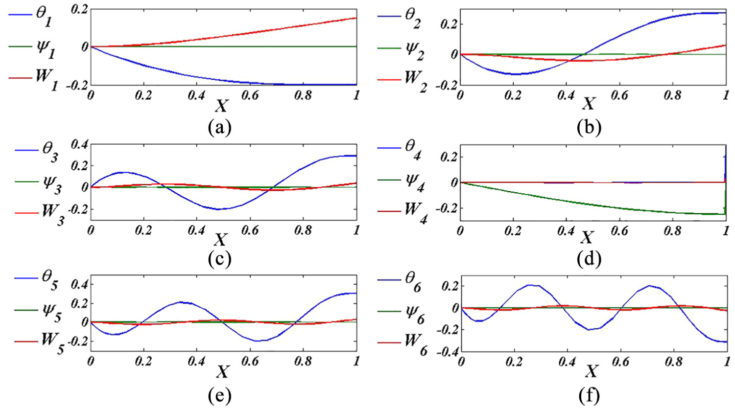
(a–f) First six non-normalized mode shapes of a composite cantilever Timoshenko beam (P = 7.5, r2 = 0.00002322, K = 0).
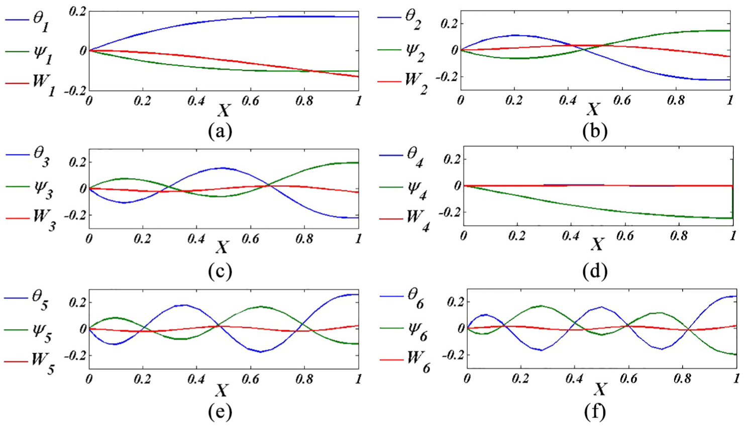
(a–f) First six non-normalized mode shapes of a composite cantilever Timoshenko beam (P = 7.5, r2 = 0.00002322, K = 0.1143).

(a–f) First six non-normalized mode shapes of a CC Timoshenko beam (P = 7.5, r2 = 0.00002322, K = 0.1143).
Figure 8 is devoted to present the first three non-normalized mode shapes of CF-CF double-beam system exposed to an axial compressive load (P = 7.5), and the beams are connected by an elastic layer with KW = 10 N/m2 and KΘ = KΨ = 10 N/rad. For these two identical beams (same cross-sectional area, same length, same material, and so on), it is clear that the first and third mode shapes (odd numbered modes) have the same magnitudes and opposite directions over the span of the beams. Also, the second mode shapes (even-numbered mode) of the beams have the same magnitudes and directions. The first three non-normalized mode shapes of a CF-CC double beams that are connected by an elastic layer with KW = 100 N/m2, and KΘ = KΨ = 100 N/rad, are shown in Figure 9.
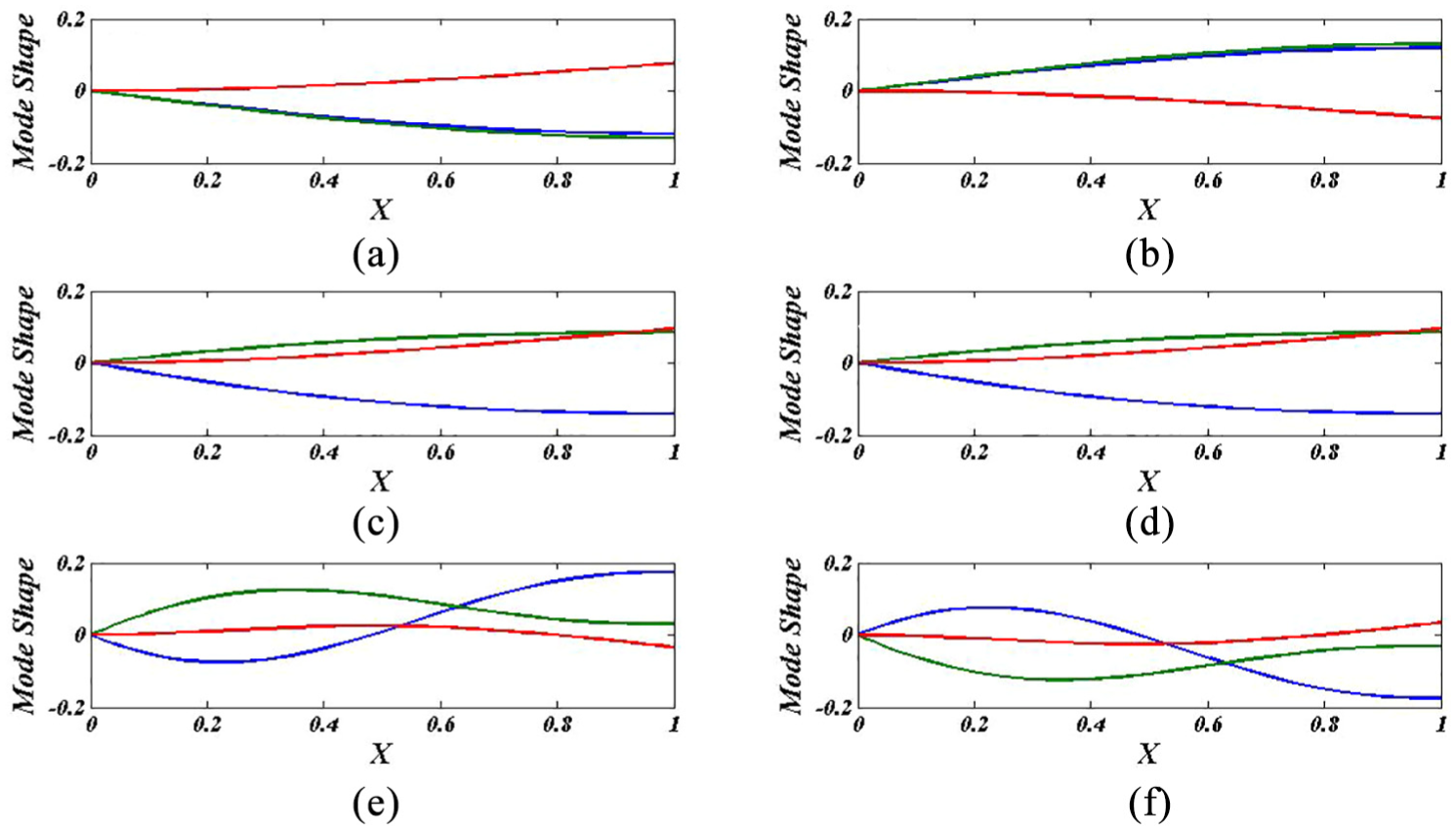
(a–f) First three mode shapes (blue: θ, green: Ψ, red: W) of a CF-CF double beam, P = 7.5, KW = 10 N/m2, andK
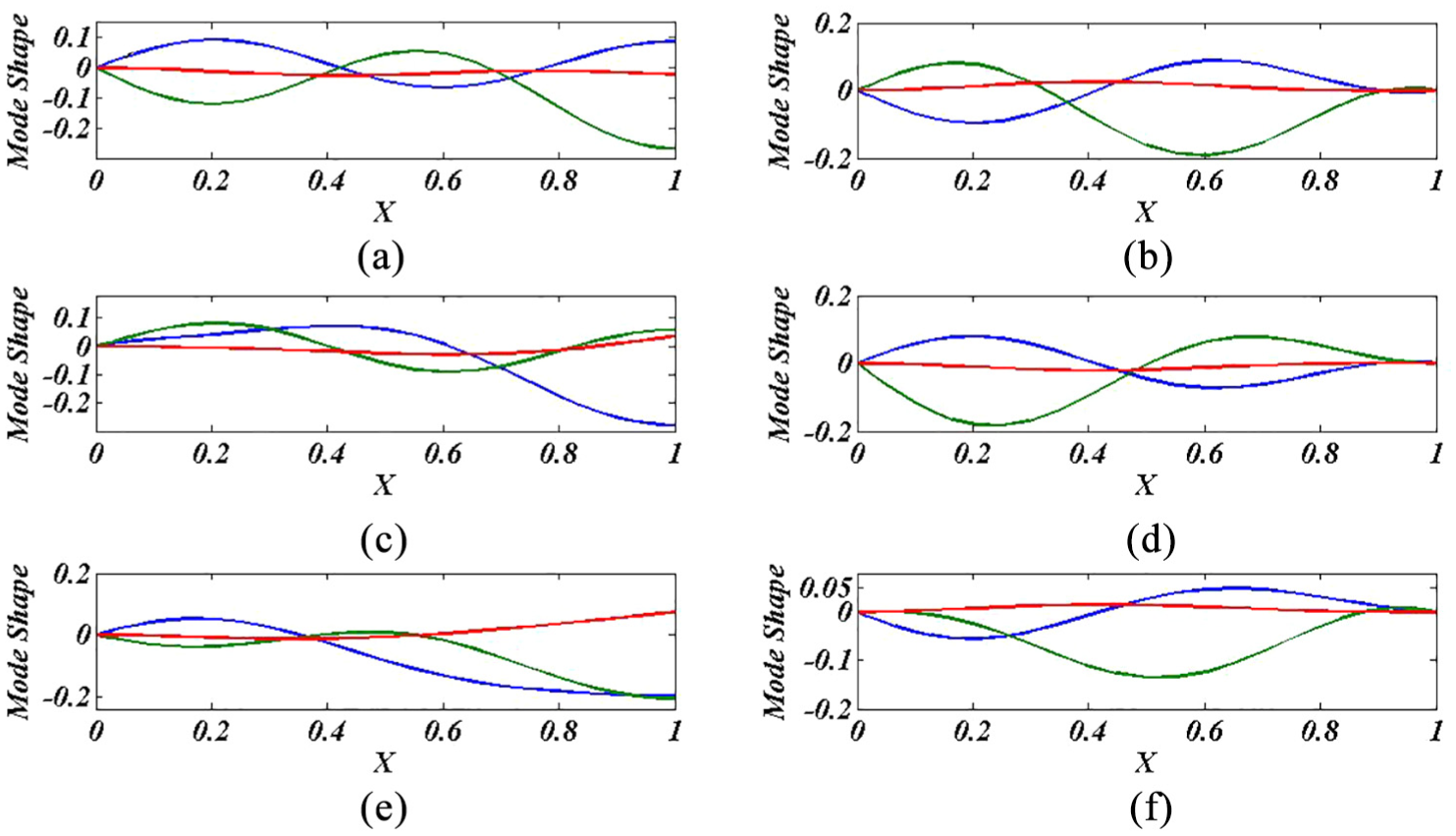
(a–f) First three mode shapes (blue: θ, green: Ψ, red: W) of a CF-CC double beam, P = 0, K = 0.114, KW = 100 N/m2, and K
In Figure 10, the effect of the axial compressive force on the first three natural frequencies of the CF-CF double-beam system with r2 = 0.01, connected by an elastic layer with KW = 10 N/m2, and KΘ = KΨ = 10 N/rad, is shown. It is noted that the natural frequencies decrease as the axial load increases. Moreover, the bending–torsion coupling has a decreasing effect on the critical buckling loads of the beam. For example, the first three critical buckling loads of a CF-CF double beam without coupling are 19.47, 170.6, and 274.3 N compared to 14.76, 31.75, and 129.9 N for the double beam with coupling. One may notice that the decrease in the critical buckling loads is more significant for higher modes. The effect of the axial compressive force on the first three natural frequencies of the CF-CF double beam at two different values of the inverse of the slenderness ratio (r2), and are connected by an elastic layer with KW = 200 N/m2, and KΘ = KΨ = 200 N/rad, is presented in Figure 11. The figure reveals that at relatively high values of the elastic layer parameters, the value of r2 has a negligible influence on the critical buckling loads.

Effect of axial force on the first three natural frequencies of a CF-CF double composite Timoshenko beam with r2 = 0.01, KW = 100 N/m2, and K

Effect of axial force on the first three natural frequencies of a CF-CF double composite Timoshenko beam with KW = 200 N/m2, K
The effect of the axial force on the first three natural frequencies of the CC-CF double beam that are connected with an elastic layer with KW = 10 N/m2, and KΘ = KΨ = 10 N/rad, is illustrated in Figure 12(a) and (b). In this case, the bending–torsion coupling has an increasing effect on the critical buckling loads. The first three critical buckling loads of the CF-CF double beam without coupling are 9.38, 160.7, and 288.2 N compared to 114.7, 210.4, and 333.5 N for the double beam with coupling. A point of interest is that the veering phenomenon occurs as the axial load increases. The veering refers to a region in which two eigenvalue loci approach each other and almost intersect as the system parameter is varied (the axial load in this case). Instead of intersecting, they veer away from each other. For instance, for the CC-CF double beam without coupling, at P = 28.14 N, there is veering between the second and the third natural frequencies. In addition, for CC-CF double beam with coupling, at P = 264.5 N, there is veering between the third and fourth natural frequencies. Furthermore, Figure 13(a) and (b) demonstrates the effect of the axial force on the first three natural frequencies of the CC-FF double beam with coupling at different parameters of the elastic layer. For the CC-FF beam connected by a layer with KW = 10 N/m2, and KΘ = KΨ = 10 N/rad, the second and third critical buckling loads have the same values. The figure shows that as the stiffnesses of the springs of elastic layer increase, the critical buckling loads increase, and the veering phenomenon between the third and fourth natural frequencies take place at P = 100.9 N.

Effect of axial force on the first three natural frequencies of a CC-CF double composite Timoshenko beam with KW = 10 N/m2, and K

Effect of axial force on the first four natural frequencies of a CC-FF double composite Timoshenko beam with r2 = 0.00002322, K = 0.1143: (a) KW = K
Tables 2 and 3 list the first six natural frequencies of the double-beam systems with different boundary conditions with and without coupling, respectively. The beams are connected by an elastic layer with KW = 10 N/m2, and KΘ = KΨ = 10 N/rad, and are under the effect of an axial compressive load (P = 7.5). These tables reveal that the bending–torsion coupling has a decreasing or increasing effect on the natural frequencies of the presented double-beam systems. For example, the coupling has a decreasing effect on the CF-CF and CC-CC double-beam systems; whereas, it has an increasing effect on the FF-CF and CC-CF beams. The CF-CF double beam denotes that beam 1 is clamped at X = 0 and free at X = 1, and beam 2 is clamped at X = 0 and free at X = 1. For the beams with bending–torsion coupling, it is noted that the CF-CF beams have the lowest natural frequencies, while the CC-CC beams have the highest frequencies. Furthermore, the first, third, fifth, and sixth natural frequencies of the FF-CF double-beam system are higher than those of the CC-CF beams. However, the second and fourth natural frequencies of the FF-CF beam are lower than those for the CC-CF beams. From these tables, it is depicted that the CC-CF beams have the lowest natural frequencies and the CC-CC beams have the highest frequencies. Also, the first six frequencies of the FF-CF beams are lower than those for the CF-CF beams.
The first six frequencies of double Timoshenko beams (P = 7.5, r2 = 0.00002322, K = 0.1143, KW = 10 N/m2, andK

The first six frequencies of double Timoshenko beams (P = 7.5, r2 = 0.00002322, K = 0, KW = 10 N/m2, and K

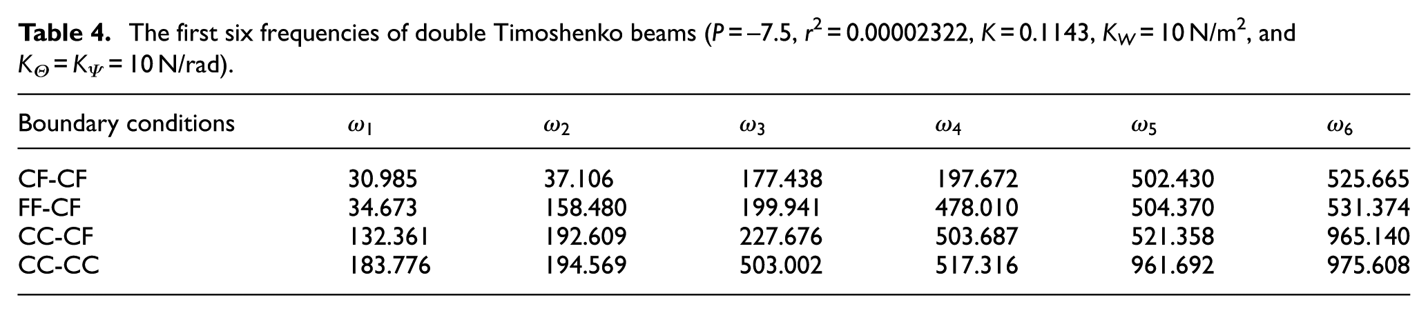
In a similar manner, Tables 4 and 5 show the first six natural frequencies of double-beam systems with different boundary conditions with and without coupling, respectively. The beams are connected by an elastic layer with KW = 10 N/m2, and KΘ = KΨ = 10 N/rad, and are subjected to an axial tensile load (P = –7.5). The coupling has a decreasing effect on the natural frequencies of the FF-CF and CC-CC double beams and an increasing effect on the natural frequencies of the CF-CF and CC-CF double beams.
The first six frequencies of double Timoshenko beams (P = –7.5, r2 = 0.00002322, K = 0.1143, KW = 10 N/m2, and K
The first six frequencies of double Timoshenko beams (P = –7.5, r2 = 0.00002322, K = 0, KW = 10 N/m2, and K

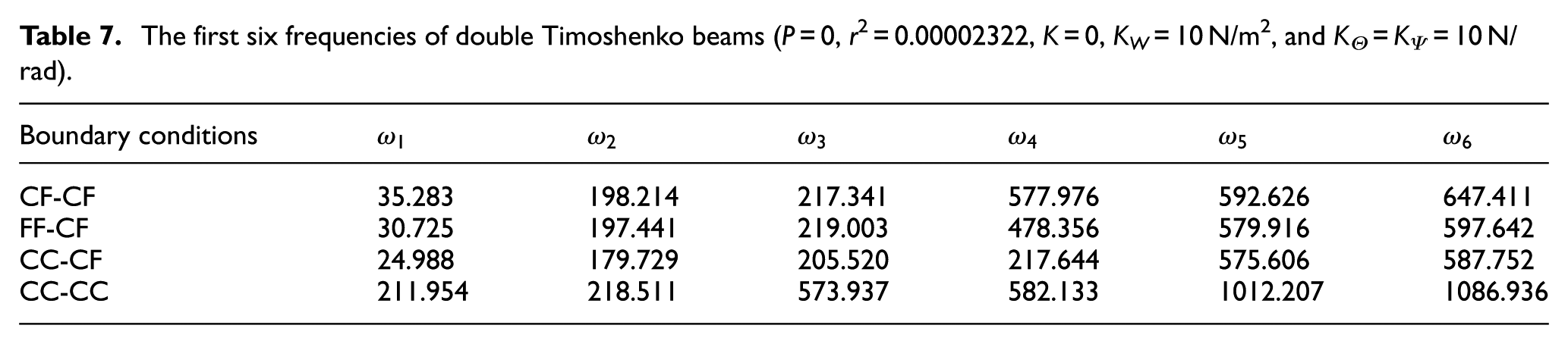
The frequencies for double-beam systems, which are not subjected to any axial force, are listed in Tables 6 and 7. It is seen that the coupling has a decreasing effect on the natural frequencies of the CF-CF, FF-CF, and CC-CC beams and an increasing effect on the CC-CF beams.
The first six frequencies of double Timoshenko beams (P = 0, r2 = 0.00002322, K = 0.1143, KW = 10 N/m2, andK

The first six frequencies of double Timoshenko beams (P = 0, r2 = 0.00002322, K = 0, KW = 10 N/m2, and K
Conclusion
The buckling behavior and the free vibration analysis of composite single and double Timoshenko beams, subjected to axial forces and featuring coupling between the bending and torsional vibrations, were investigated. The double beams were connected by a continuous elastic translational and rotational springs. The Chebyshev spectral collocation method was used, and the governing PDEs of motion were discretized. Then, the resulted eigenvalue problem was solved to obtain the critical buckling loads and the natural frequencies. The effects of the axial forces, the elastic layer parameters, the coupling between the bending and torsional vibrations, the slenderness ratio, and the boundary conditions on the critical buckling loads and the natural frequencies were studied. The obtained results show that the bending–torsion coupling has a declining effect on the natural frequencies and the critical buckling loads of single beams, whereas it has a decreasing or increasing effect on the natural frequencies of double beams. Moreover, the veering phenomenon between the frequencies of double beams was observed as a result of varying the axial loads.
Footnotes
Handling Editor: Muhammad Akhtar
Declaration of conflicting interests
The author(s) declared no potential conflicts of interest with respect to the research, authorship, and/or publication of this article.
Funding
The author(s) received no financial support for the research, authorship, and/or publication of this article.