
Abstract
Coupled vibrations are difficult to overcome in automatic transmission with mixed gear trains. In this study, a mathematical model for the bending–torsional–axial–oscillation vibrations of mixed gear trains with parallel-axis gear pairs, a clutch, planetary gear sets and a shaft rotor was developed using the concentrated mass method. The dynamic vibration response and transmission error of the meshing gears in different gears were analysed. The response sensitivity of the vibration parameters was obtained using the design coupling function of the peak–peak dynamic transmission error. The degree of coupling of each part with system vibrations was analysed and it was found that the stiffness and damping of gears influenced the coupled vibrations. Finally, the top seven degrees of coupling were obtained, the first two contributions were taken as the target to improve, the thickness of the P1 gear ring was increased by 5 mm and the bushing was added between the P2 planetary and sun gear to increase the stiffness and damping of gears. It could be validated that the vibration performance improved significantly from 3% to 6%. This article presents an analytical method of theoretical and practical value, which can provide a strong basis for reducing the vibrations and noise in automatic transmission.
Keywords
Introduction
The vibrations and noise occurring during automatic transmission (AT) affect the driving comfort of a vehicle. Rapid developments occurring in the AT technology not only satisfy the demands for a vehicle’s dynamic performance but also ensure driving comfort. 1 Vehicle comfort includes not only driving comfort, 2 but also the vehicle’s vibrations and noise levels. 3 The connection structure of AT is complex because the transmission system is made up of mixed gear trains with parallel-axis gear pairs, a clutch, planetary gear sets and a shaft rotor. 4 Owing to the relationship between structural coupling and gear meshing frequency, not just the gear meshing but also the entire mixed gear coupling system should be taken into account. Thus far, no comprehensive theoretical methods have been put forth to solve the problem of coupled vibrations and noise of the compound gear train in AT.
To improve the vibrations and noise performance of gears, many scholars studied the vibration characteristics of spur gears or planetary gears. J Wei 5 studied the influence of dynamic driving error and vibration stability of helical gears. G Liu and RG Parker 6 studied the dynamic behaviour of gear systems under different working conditions. MR Kang and A Kahraman 7 studied the dynamic response of double-helix gear pairs based on experimental and theoretical analyses. Jauregui and Gonzalez 8 developed a single degree-of-freedom (DOF) model to study the axial vibrations caused by the manufacturing error of the double-helix gear. A Kahraman 9 analysed the load distribution characteristics of planetary gear transmission. J Lin and RG Parker 10 analysed the inherent characteristics of free vibrations of planetary gear systems. However, these studies focus only on the vibrations or coupled vibrations of gears, shafts and bearings, and do not study the vibrations of compound gear trains in AT.
Previously, studies were conducted to evaluate the vibrations and noise performance of transmission systems. LX Chang et al. 11 use the nonlinear lateral torsion coupling mode of a vehicle transmission system to study the response sensitivity and evaluate nonlinear vibrations. HW Lee et al. 12 carried out a study on the vibration characteristics of vehicle transmission. Anderson et al. 13 established a test rig for the twin planetary gear mechanism and measured the vibration amplitude of the system using an accelerometer. However, there is not much information available on the coupling. Sondkar and Kahraman 14 developed a three-dimensional (3D) dynamic model on a dual planetary gear mechanism consisting of a gear mesh and bearing supports; it is concluded that different values of stagger are shown to excite different types of modes, resulting in different dynamic response curves. G Kouroussis et al. 15 conducted dynamic vibration analysis of vehicle and powertrain based on AT. Although these results involve coupled vibrations of AT, there are still three points that should be considered:
A large number of studies are available on the vibrations and noise of a single pair gear, while only a few studies are available on vibrations occurring in compound gear sets during transmission;
There are more studies on bending–torsional vibrations and less on bending–torsional–axial–oscillation vibrations in mixed gear trains;
There are more studies on the vibration characteristics of gears and less on the response sensitivity of the vibration parameters.
AT involves multiple meshing gears for certain gears 16 and a dynamic response is generated due to transmission speed and torque; 17 furthermore, coupled vibrations are caused by multiple excitation sources and are transmitted by the structure. 18
The major contribution of this work lies in studying the coupled vibration principle of mixed gear trains for AT; a method is proposed to control the vibrations and noise during transmission. First, an eight-speed AT 19 was considered as the research object. Based on the mathematical theoretical analysis, 20 a mathematical model of the bending–torsional–axial–oscillation vibrations of mixed gear trains containing parallel-axis gear pairs, a clutch, planetary gear sets and a shaft rotor was designed. Second, the dynamic vibration response and transmission error of the meshing gears in different gears were analysed along with the degree of coupling of each part to the system vibrations and the response sensitivity of vibration parameters was evaluated. Third, techniques to reduce dynamic transmission error and vibration dynamic response were proposed by optimising gear stiffness and damping; these techniques were validated experimentally. This study is expected to form a theoretical and practical integrated design method for noise/vibration/harshness (NVH) control in AT.
Model for coupled vibrations
Coupled vibrations are difficult to overcome in AT with mixed gear trains. It was found that there occurred a series noise in the fourth driving gear (D4) during eight-speed AT; the noise sources were gear 4 and gear 7 (G4 and G7, respectively; Figure 1). At first, we only modified the profile modification of gear 4 and gear 7(G47 for short), but did not improve the vibrations. Later, we found that the noise of G47 improved significantly after changing the microscopic parameters of other meshed gears, and at the same time it was found that vibration coupling occurred between meshed gears.
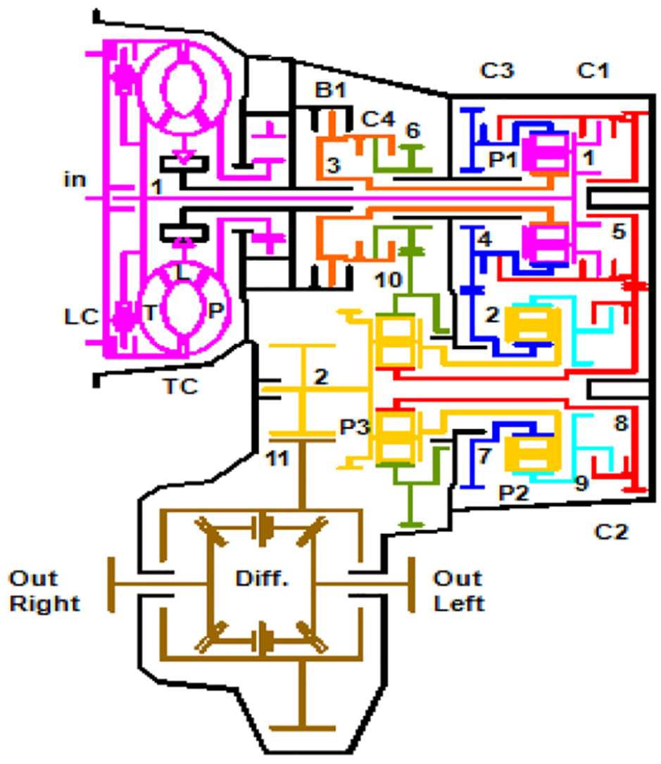
Layout of the eight-speed automatic transmission.
Figure 1 shows the transmission layout of the proposed AT. The numbers represent shaft numbers. If there is a gear attached to a shaft, the number of the gear is the same as the number of the shaft (e.g. G2 stands for gear 2 and G5 stands for gear 5). There are five multi-plate shifting elements, three planetary gear sets and three parallel-axis gear pairs connected by two parallel axes.
The first planetary gear set (P1) on the first axis splits the input power to the pinion gear of the three parallel-axis gear pairs (G5 and G8, G4 and G7, and G6 and G10), which provide three paths for power flow from the first axis to the second axis. The second (P2) and third planetary gear sets (P3) are on the second axis. The final gears G2 and G11 are arranged between the second axis and the output axis. Gear G2 is arranged on the second axis and gear G11 is connected to the differential housing. Power is transferred to the output shaft, and at the same time the differential balances the different speeds of the two wheels. The five shifting elements link certain gear elements together or to the transmission housing. Brake B1 and clutches C1, C3 and C4 are on the first axis, while clutch C2 is on the second axis. The shift elements are either closed or opened to achieve a specific certain gear ratio. The shift logic is given in Table 1.
Shift logic of the eight-speed automatic transmission.
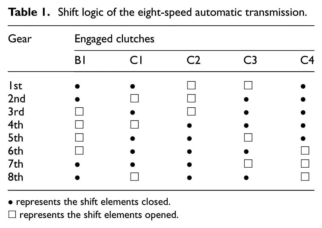
• represents the shift elements closed.
□ represents the shift elements opened.
A novel structure is suggested for the eight-speed AT; the shift logic is ‘simple shifting’ (open one clutch and close another clutch) and the gear ratio is perfect for the vehicle speed.
Power is input from the left side of the planetary carrier through different clutches and brakes are used as the controls, which can realise different gears. Each gear has five shift elements: three closed and two opened; this results in a specific ratio of transmission.
From Table 1, it can be seen that C2, C3 and C4 are closed and B1 and C1 are opened in D4 gear. Figure 1 shows the gear G4 and P1 ring gear is fixed connection as one component, the gear G7 and P2 sun gear is fixed connection as one component, the gear G4 and gear G8 is connected by clutch C3 closed. Different gear and planetary sets act as the fixed connection, thereby forming mixed gears of parallel-axis gear pairs and planetary gear sets. These form coupling points with interconnected elements in the power transfer process. Figure 2 shows the connection of different meshed gears in the D4 gear.

Coupling components of D4 gear.
In this section, we analysed the route of power flow in D4 gears and used the method of substructure decomposition, according to the form of the conjugate gears, to determine the excitation source of the transmission gear system.
The vibration model of bent–torsional–axial–oscillation for helical gears
Because of the axial dynamic meshing force in helical gears, there are not only bent vibration, torsional vibration and axial vibration, but also oscillation vibration. So it is necessary to establish the model for a coupled gear system.
In order to simplify the model, the friction force of meshing gear and torsional elastic deformation of the transmission shaft are not considered, and the transverse bending of the transmission shaft is simulated with stiffness and damping. The vibration model of bent–torsional–axial–oscillation for helical gears is shown in Figure 3.

The vibration model of bent–torsional–axial–oscillation for helical gears.
From Figure 3, an 8-DOF system is established in the 3D space, and the generalised displacement array

where
Displacement array of the bending–torsional–axial–oscillation vibrations
In D4 gears, the clutches C2, C3 and C4 are closed; four pairs of external meshing gears, G58, G47, G610 and G211, are included along with three planetary gears, namely, P1, P2 and P3. Each excitation source has four directional bending–torsional–axial–oscillation vibrations. Furthermore, each excitation source is connected by the clutch and spline, which causes coupled vibrations. The power flow route of D4 is shown in Figure 4.

Power flow route in a mixed gear system in D4.
Therefore, for D4 gears, the generalised displacement array of bending–torsional–axial–oscillation vibrations is expressed as


where parallel-axis gear
In addition,
The coupled vibrations of mixed gear trains can be defined as

where [m] is the mass matrix defined as

[c] is the damping matrix defined as

[k] is the stiffness matrix defined as


According to these equations, the vibration of every part is coupled to that of the others. Changing the structural parameters of any part will affect the parts that are coupled. Assuming that damping is not taken into account, the vibration displacement
Principle of coupled vibrations
Coupled vibration refers to the phenomenon in which the input and output of two or more components interact with each other and transfer energy from one side to the other through interaction. Depending on the deformation direction, vibrations can be divided into bending vibration, torsional vibration, axial vibration and oscillation vibration.
Bending vibration
The bending vibration equation of G4 is shown below

The bending vibration equations of other gears are similar.
Torsional vibration
The torsional vibration equation of G4 is shown below

The torsional vibration equations of other gears are similar.
Axial vibration
The axial vibration equation of G4 is shown below

The axial vibration equations of other gears are similar.
Oscillation vibration
The oscillation vibration equation of G4 is shown below

The oscillation vibration equations of other gears are similar.
Torsional vibration of the clutch
When the clutch is incorporated into the gear drive system for dynamic vibration analysis, only the direction of torsional vibration is considered. Suppose that

The torsional vibration equations of other clutches are similar.
Here
According to equations (3) and (9), if the coupling effect between structures is not considered, the vibration displacement in the torsional direction of G4 is only related to conjugate gears

If the coupling effect between structures is considered, the vibration displacement in the torsional direction of G4 is

Equation (14) shows that the vibration displacement of G4 is positively correlated with the vibration displacement of other gears. If the vibration displacement of other structures is reduced, the vibration of G4 can be reduced by reducing the vibration coupling.
Vibration analyses of gear trains
As a professional multi-body dynamic simulation tool for transmission systems, Romax can fully consider the bending–torsional–axial–oscillation vibrations. At the same time, the coupled vibrations between different excitation sources can be simulated by the microstructure and dynamic response analysis.
Connection of meshing gear in D4
The connections between different meshing gears of D4 are shown in Figure 2. G58, G47, R1 and R2 are connected by one clutch, while G610 and S1 are connected by a second clutch. The rest of the connections are fixed.
Romax model of AT
A multi-body dynamic model is built using Romax, in which the gear, bearing and spline are parameterised and the shaft and case are imported by the finite element method. This model takes into account the meshing characteristics of gears and other parts and the supporting characteristics between them. The model is shown in Figure 5.

Multi-body dynamics model constructed by Romax.
Parameter design
In order to ensure the reliability of the obtained results, the micro-modification parameters of five other pairs of meshing gears were also varied; the variation was set at 10 µm (see Table 2 for details). Working condition 1 yields the basic data to calculate the coupling degree. The helix slope deviation of the gear (fHβ deviation of condition l) is adjusted by 10 µm in working conditions 2–6. Figure 6 shows a schematic diagram of fHβ.
Different working conditions of active gears.

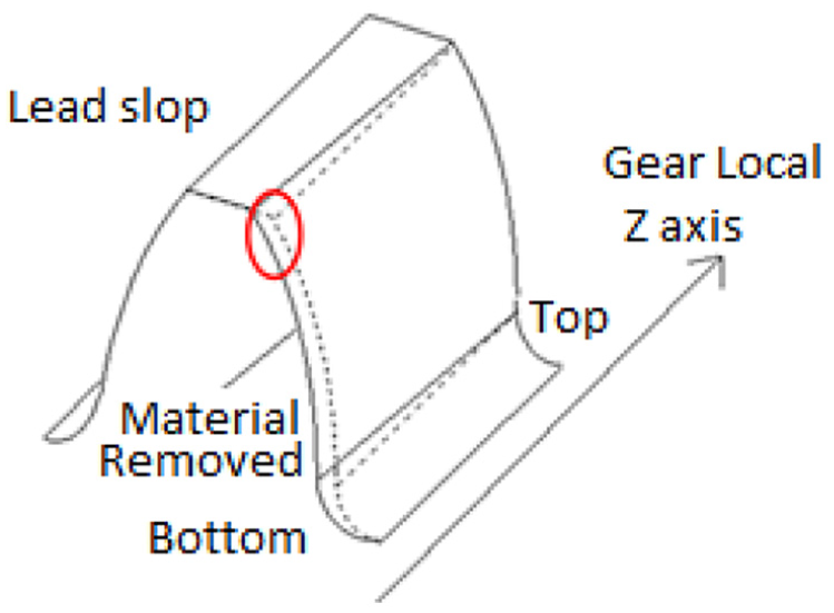
Schematic diagram of fHβ.
Vibration analysis of all the gears
Transmission error is a parameter used to describe the tolerance of gear transmission. In the process of gear working, the difference position between the actual position and the calculated value is the transmission error.
Transmission error is expressed as the deviation of rotation angle

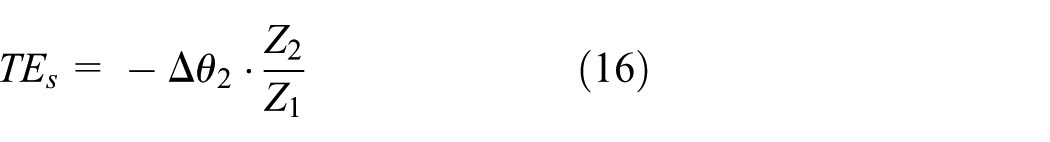
For convenience, the transmission error is expressed as the deviation of mesh displacement on the mesh line

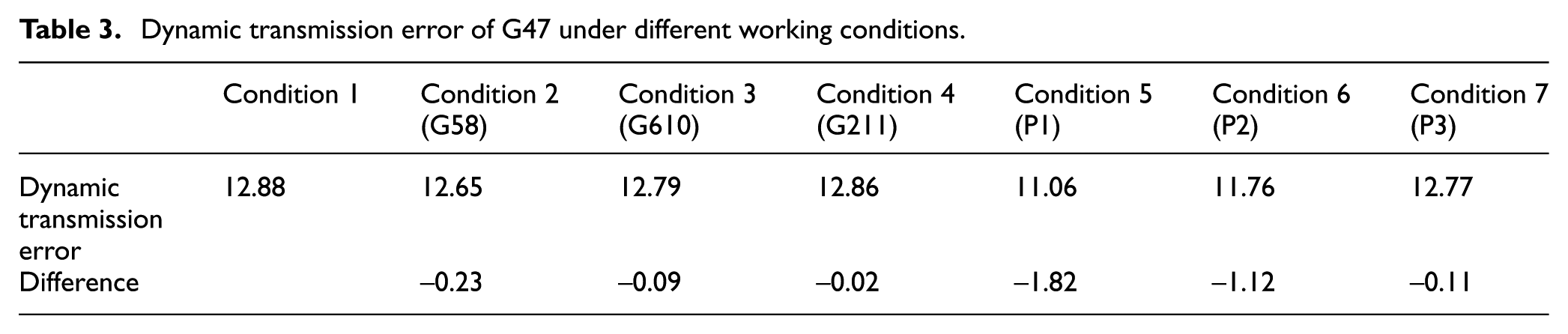
The dynamic transmission error of G4 under working condition 1 was calculated as the basic data, after which the parameters of other gears (working conditions 2–6) were changed and the dynamic transmission error of G4 was recalculated (see Table 3 for details).
Dynamic transmission error of G47 under different working conditions.
Coupling degree design
It can be seen from Table 3 that the dynamic transmission error of G47 is different after the parameters of other gears (working conditions 2–6) were changed. Therefore, the coupling degree of G47 can be defined as the difference in the rate of dynamic transmission error of other meshed gears relative to the transmission error in working condition 1 as shown in the following equation

where
The coupling degree of other meshing gears with G47 under different working conditions is obtained using the equation for coupler design. See Table 4 for specific data.
The coupling degrees of other meshing gears with G47.

It can be seen from Table 4 that the coupling degree of other meshing gears with G47 is in the order of

As shown in Table 4, G47 exhibits a large coupling degree with other gears because G47 is directly connected to P1 and P2, resulting in a larger coupling degree of the above-mentioned meshing gear with G47. It has been proved that the coupled vibrations of meshing gears are related to structural transmission.
Methods of reducing coupled vibrations
It has been proved that the coupled vibrations of G47 gear can be reduced by improving the vibration of P1 and P2, and the vibration can be decreased after increasing its stiffness k. The following two methods are mainly used to reduce the vibration and noise of G47, and the two methods are verified by simulations and experimental testing.
Simulation verification
Method 1: damping and stiffness of the structure
In the transmission system, the thickness of the gear ring of P1 was 5 mm. To improve the vibration and noise level of G47 by Romax simulations, the thickness of the gear ring was increased to 10 mm (Figure 7).

Increase in the thickness of the P1 ring.
As shown in Table 5, as vibrations decreased with an increase in part thickness, the vibration coupling degree of G47 decreased and the vibration acceleration amplitude of G47 decreased from 2.6 to 2.32 m/s2.
G47 vibration acceleration with an increase in P1 ring gear thickness.

Method 2: increasing the support stiffness
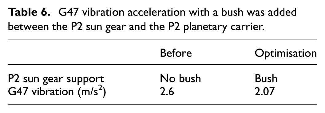
The P2 sun gear was supported by planet gears. To improve the vibration and noise level at G47, a bush was added between the P2 sun gear and the P2 planetary carrier. The vibration acceleration amplitude of G47 was simulated and analysed, as shown in Figure 8.

Increase in the stiffness of the radial support.
As shown in Table 6, after the bush was added between the P2 sun gear and the P2 planetary carrier, the radial support stiffness of the P2 sun gear increased and its vibrations decreased. The vibration coupling degree of P2 sun gear with G47 was reduced, which finally reduced the vibration acceleration of G47 from 2.6 to2.07 m/s2.
G47 vibration acceleration with a bush was added between the P2 sun gear and the P2 planetary carrier.
Test verification
Figure 9 illustrates the vibration test setup of the transmission in a vehicle. The vibration accelerometer was fixed on gearbox housing near the gear G47. The microphone was placed in a seat near the driver’s ear. And at the same time, a speed sensor was fixed to monitor the driving speed of wheel. An accelerometer and a microphone were connected to the test equipment, and the test equipment was connected to a computer, as shown in Figure 10.

Vibration test setup of transmission in a vehicle.

Vibration test setup of transmission in a vehicle.
The noise level of the transmission was tested before and after optimisation on the base band modem (BBM) test equipment from Mueller Company, Germany. The key parameters of the equipment are as follows:
Number of channels: 16;
Maximum sampling frequency: 102.4 kHz/channel;
Maximum analysis bandwidth: 40 kHz;
Analogue-to-digital conversion: Sigma-Delta type, 24-bit precision;
Phase accuracy: <0.2@10 kHz.
The gear box is driven by an internal combustion engine (ICE), and the wheel will move forward. The speed of ICE is controlled from 750 to 3500 r/min in D4 gear, and the vibration data are collected from the accelerometer and microphone, which are time-domain signals. The corresponding order of noise pressure level of each gear is obtained by Fourier transform.
The two modes of the vibration coupling reduction described in the previous section were verified experimentally.
Method 1: damping and stiffness of the structure
Figure 11 shows the noise data of G47 before and after changing the P1 ring gear thickness (the thickness of P1 gear ring changed from 5 to 10 mm). The red dots represent the noise before improvement and the blue dots represent the noise after improvement.

Comparison of G47 noise level data.
The vibrations of G47 were decreased by 4–8 dB, and the noise level was improved by 3%–6% after increasing the P1 ring gear thickness.
Method 2: increasing the support stiffness
In the case of vibration coupling between the P2 sun gear and gear G47, the vibration energy of the P2 sun gear is diverted by adding a bearing bush between the P2 sun gear and the P2 carrier. The location of structural changes is shown in Figure 12.

Structure of P2 sun gear.
As shown in Figure 13, after adding a bearing bush support between the P2 sun gear and the P2 planetary carrier, the noise level of G47, which was caused by a dynamic drive error, was decreased by 2–10 dB and the noise level was reduced by 3%–6% after adding the bush.
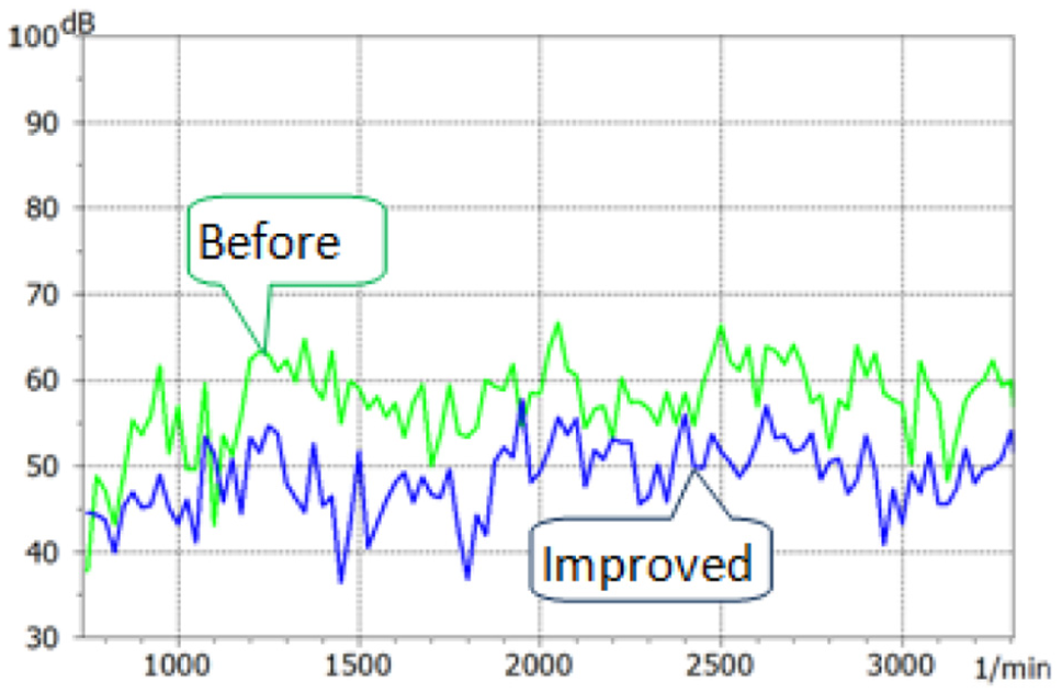
Comparison of G47 noise level data.
Conclusion
This study analysed the coupled vibration principle of AT to obtain an effective method for controlling vibrations and noise. The following conclusions were drawn from the obtained results:
A model for the bending–torsional–axial–oscillation vibrations of mixed gear trains containing parallel-axis gear pairs, a clutch, planetary gear sets and a shaft rotor was established and the dynamic response of the gear pairs was studied.
The dynamic characteristics and dynamic transmission errors of the gears were analysed and the vibration coupling degree of the system was evaluated, and the top two degrees of coupling were chosen as the target to improve.
The vibrations reduced and the noise could be improved by increasing the thickness of the P1 gear ring by 5 mm and adding the bushing between the P2 planetary gear and sun gear to increase the stiffness and damping of gears.
The optimised results were validated experimentally and it was found that the noise could be improved by 3%–6%.
An integrated method was established for analysing the coupled vibrations and dynamic response of AT; this model has particular significance for dynamic vibration response analysis and can be used to effectively reduce vibrations and vehicle noise.
Footnotes
Handling Editor: Ali Kazemy
Declaration of conflicting interests
The author(s) declared no potential conflicts of interest with respect to the research, authorship and/or publication of this article.
Funding
The author(s) disclosed receipt of the following financial support for the research, authorship and/or publication of this article: The authors acknowledge the financial support provided by the National Science Foundation of China (Grant No. 51705012) and The National Project to Strengthen Industrial Foundation Development of China (Grant No. TC150B5C0-23).