
Abstract
It is an important guarantee to precisely measure multi-dimensional force vector with variable directions. In this article, variable force ratio (force ratio is a concept of a ratio of maximum force over minimum force) test system based on piezoelectric effect is proposed to meet the requirement of force measurement characterized with variable force ratio. Force error analysis model of test system is established. Variable force ratio loading device is designed, realizing force ratios of loading forces from 1.4 to infinity by changing loading angle. The orthogonal static calibration, variable force ratio loading experiments as well as dynamic calibration can be completed based on the above systems. The results of orthogonal static calibration express that when resultant loading force is 5000 N, the maximum nonlinearity of X, Y, and Z direction is 1.95%, repeatability is only 0.06%. The results of static calibration of variable force ratio show that when angle is 2°, 5°, 10°, and 30°, the average deviation is 111.9 N (2.2% full of scale). The results of dynamic calibration show that the first natural frequency of test system is 463.99 Hz, which is twice the minimum test frequency (200 Hz). The results of tests reflect dynamic and static characteristic of variable force ratio test system. The system can be utilized for universal variable angle large force measurement (>500 N) in vector control engine (thrust vector control engine), friction stir welding, and large manipulator.
Keywords
Introduction
The demand of precisely measure three-dimensional forces with variable angle of direction simultaneously is increasing in experiments and practical applications, like aerospace, robot, biomedical engineering, manufacturing, and so on. 1 Variable angle of force vector is a universal characteristic of many force-generating devices showing the direction of the forces. Thus, it is essential for force-measuring instrumentation to precisely measure forces with variable angle arrangement.
There are some papers previously involving measuring and calibrating forces with variable angle arrangement.2–4 Aiming large forces with variable loading angle, applications in aircraft rocket engine, and friction stir welding has aroused great concern in scientific researchers. Especially in thrust vector control (TVC) engine,5,6 as one of key experiments is focused on large force measurement with variable angle, it is required to ensure accuracy of fast motion in TVC engine. Different from characteristics of fixed injection direction of nozzle in non-TVC engine, the injection directions in TVC engine change with its angle in real time, resulting in a rapid change of magnitude and direction of thrust vector, so it is difficult to guarantee high-precision test of thrust vector with variable loading angle. 7 In addition, in order to represent the real-time state of variable angle thrust vector accurately, high-frequency measurement, which makes it difficult to accurate thrust measurement, 8 is needed. Overall, solving variable angle thrust vector test in high frequency is a core technology of force measurement in TVC engine. 9
The previous studies of TVC engine are of widely concerned about thrust control and structure design, while those of force measurement are relatively small. As for TVC engine of fighter, US F-22 Raptor fighter was measured for real-time force vector with variable angles (±20°). M Mansell 10 introduces that British aerospace public limited company utilizes three piezoelectric wafers of 1000 lbs preloads to measure forces of a vertical and/or short take-off and landing (V/STOL) fighter. Thrusts of TVC engine developed by USSR, Germany, United Kingdom, France, and other European countries are measured accordingly.11,12 As for test model of TVC engine, many previous papers are studied. Mikiya Araki 13 from Japan Aerospace Exploration Agency measured thrust of a rectangular hypersonic nozzle using an inclined baffle plate. A 1:100-scale model of the hypersonic nozzle is manufactured, and its resultant thrust was investigated. Yu Youan 14 devises six-component boxlike balance, overcoming vector nozzle’s weight and unbalance between force and torque, decreasing vibration of stand. China Gas Turbine Establishment 15 develops six-component force measurement system with axial of 15 kN in high rigidity and stability. Fu Raoming 16 develops a novel six-component force measurement system with table balance structure and accomplishes static and dynamic test. Zhen Huahai 17 develops a strain measurement balance to measure thrust, solving connection problems of nozzle and balance with advantages of large load and high stability.
Force ratio is a relationship between maximum force (Fmax) and minimum force (Fmin) as shown in Figure 1. Variable force ratio (VFR) enables to follow force arrangement with loading angles, so force ratio is a key parameter representing force measurement in angle variation. Magnitude of force ratio brings measurement difficulties. In the case of small force ratio, ranges of all directions are relatively close, and between them appear, so the problem of decoupling vector forces in multiples ranges must be solved. While as for large force ratio, force in large range is almost 10 times than that in small range that tend to submerge, and interference of large range to small range is severe, so the problem of vector force decoupling in small range must be solved. In a word, forces with VFR must be investigated, while few studies are published.

Description of variable force ratio (VFR).
As an important intelligent material, piezoelectric quartz has received widespread attention of researchers because of its high rigidity, high natural frequency, and excellent static characteristics and is especially suitable for high-frequency dynamic force measurement.18,19 In this article, taking the problem of vector force test of TVC engine as an example for measuring forces with variable loading direction, VFR test system based on piezoelectric effect is designed to meet the requirement of thrust vector characterized with VFR. Force vector measurement at different values of the angle arrangement is simulated in the system, and role of the factor is studied. In order to simulate the force loading state in TVC engine, and VFR loading device is designed by changing force direction. Second, in order to improve accuracy of force determination at different force ratios, position and motion errors of key components in transmission chain are analyzed; then the error analysis of VFR loading device is completed. Third, parallel support device is designed to reduce loading error, improving loading accuracy determination. For VFR test system, orthogonal static calibration and VFR loading experiments are completed. Finally, modal analysis is utilized, 20 in order to assess dynamic performance of the test system.
VFR test system
Force test analysis of thrust vector engine
Thrust vector engine includes baffle type, binary type, axisymmetric type, spherical convergent type, and fluid type. 21 As a mature thrust vector technology, the binary type avoids low life expectancy and low reliability caused by complex mechanical driving mechanism, which is applied to F-22 Raptor fighter.22,23 Binary vector nozzle in F-22 consists of four pieces of adjustment sheet. Rotating two pieces of convergence adjustment sheet can change throat area. Rotating two pieces of diffusion adjustment sheet can not only change ventilating area, but also achieve thrust rotation, which can achieve ±20° injection of vector force. Thus, the vector force test for binary vector nozzles should meet following requirements:
High stiffness requirement. Based on the experimental requirements, according to the different size test model, ranges are from several thousands to hundreds thousands N, so force-sensitive elements and their structure must have the ability to withstand big loadings.
High-frequency requirement. The turning rate of AL-31FU’s engine reaches 30°/s, and Lockheed’s F-16 VISTA AVEN vector thrust engine has a maximum reachable turning rate of 50°/s. 24 Therefore, the high turning rate proposes a challenge to the frequency response characteristics of force-sensitive element. If the nozzle deflection speed is 20°/s and nozzle deflection speed accuracy is 0.1°, the test frequency of force-sensitive component must be as high as 200 Hz.
High measurement precision requirement of force with VFR. When the turning angle is 20°, the force ratio is up to 3.3. Vector force test should follow interference between all direction forces. Especially, in force measurement with large range ratio, the small range of force is easily disturbed by the large range of force.
VFR test system
In order to realize VFR loading and measurement, VFR test system is devised, as shown in Figure 2. The whole system mainly contains dynamometer, lateral loading device, rigidity support, and VFR loading device. The VFR loading system can produce forces with hydraulic loading system, which transfer to piezoelectric dynamometer that produces induced chargers, realizing force measurement in three directions. Piezoelectric dynamometer uses four-square-sensor layout to measure forces in X, Y, Z directions. Layout of four-square sensors not only simplifies calculation, but also compensates error of deflection caused by low rigidity and ambient environment. Rigidity support mainly uses stiffener to strengthen rigidity, guaranteeing position precision of all parts.
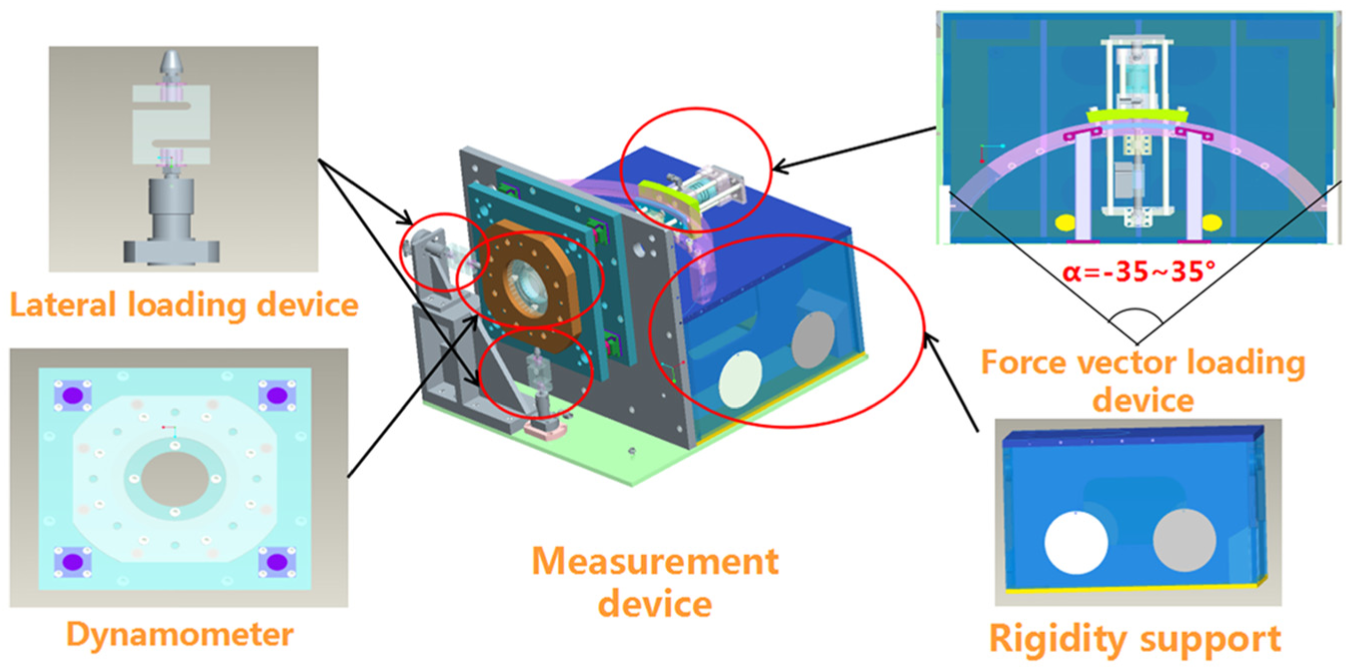
VFR test system.
Based on the test requirement of high frequency and variable angle, the system used piezoelectric chips as force-sensitive components. Piezoelectric sensors have the characteristics of high stiffness and high frequency (the highest quartz frequency is 200 kHz). Piezoelectric sensor and piezoelectric chip are shown in Figure 3; the size of piezoelectric was of 55 × 55 × 60 mm. Upper and lower plates adopt stainless steel (1Cr18NiMoV), which has the characteristic of anti-magnetic and antirust. Other parts of body structure were made of ductile iron (Q350).

Piezoelectric sensor and piezoelectric crystal.
VFR loading device, as a key part of the main system, realizes not only force but also calibration in main direction. Lateral loading devices of X and Y directions are laid in Y, X directions, respectively. Hydraulic forces of Y and X directions can be generated in hydraulic cylinders of lateral devices. Therefore, in lateral force calibration, lateral forces in Y, X directions can be generated by lateral devices with hydraulic loading principle.
Assuming that four sensors can separately measure forces


Layout of force sensors.
Analysis and structure improvement of VFR test system
Force error analysis of VFR test system
Based on error analysis of multibody system, this section aims at calculating force deviation between theoretical and practical loading position based on VFR loading device. VFR loading device mainly contains dynamometer, arc guide, hydraulic loading device, and loading rod, as shown in Figure 5. Coordinates of four parts R0, R1, R2, and R3, and origin of coordinates O0, O1, O2, and O3 are separately followed. Ideally, practical center of dynamometer O0 coincides with center of loading rod center O3. Because manufacturing errors of devices, two centers do not coincide in practice, which causes force deviation. Thus, this article mainly studies force deviation of O0 and O3.

VFR loading device.
In force transfer process, forces are generated by hydraulic loading device, forming a force transferring trace of arc guide, hydraulic loading device, loading rod, dynamometer. Deviation of loading rod center O3 is mainly caused by error coupling of three parts: arc guide, hydraulic loading device, and loading rod. Thus, based on error analysis of multibody system, errors due to arc guide, hydraulic loading device, and loading rod are studied, separately numbered as parts 1, 2, 3. Topological structure of three parts is shown in Figure 6.

Topological graph of error analysis.
In order to analyze errors of all parts, in consideration of manufacturing and assembly errors, assuming movement displace errors of part i (i = 1–3) in X, Y, Z directions are
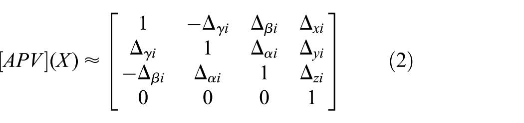
Similarly, matrix of movement in Y and Z direction and rotation from X, Y, Z axis are separately

where
1. Arc guide
Arc guide center is directly connected with stand and does not move in process of loading, so
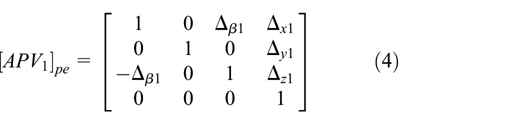
2. Hydraulic loading device
Hydraulic loading device connected with arc guide can move under loading process and simultaneously change angle, so
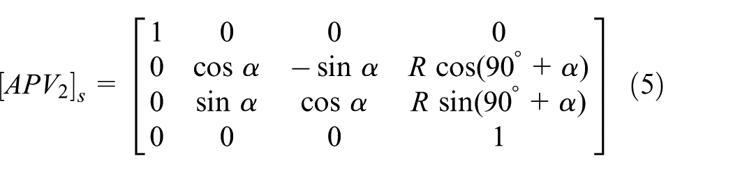
Similarly, because hydraulic loading device rotates from X axis, displace error caused by α can generate errors

3. Loading rod
Loading rod connected with arc guide and dynamometer can move in loading process and simultaneously change angle, so

Similarly, because loading rod rotates from X axis, displace error caused by α can generate errors

With the obtained matrix
Self-alignment device restricts loading center, decreasing errors in all directions. As shown in Figure 7, self-alignment device mainly contains center pillar and loading cover. Center pillar and loading cover are directly connected, making vector force transfer from center pillar to piezoelectric dynamometer, restricting errors in X, Y, and Z directions and realizing high measurement precision. Moreover, it also restricts angle error from Y and Z axes. In order to illustrate error restricted degree of self-alignment device, restricted coefficients are introduced.

Self-alignment device.
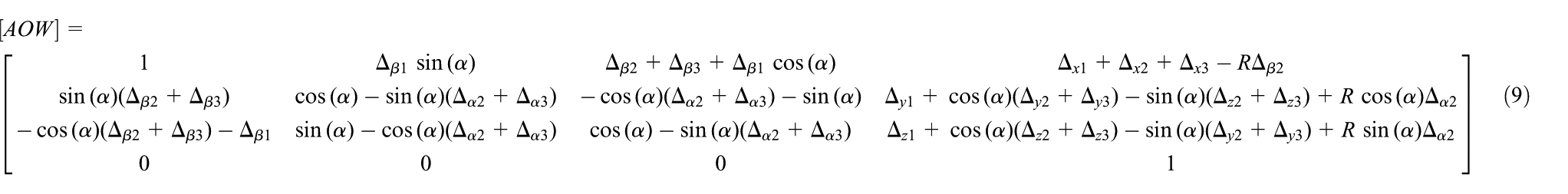
Based on error transfer matrix

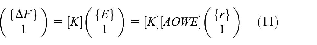
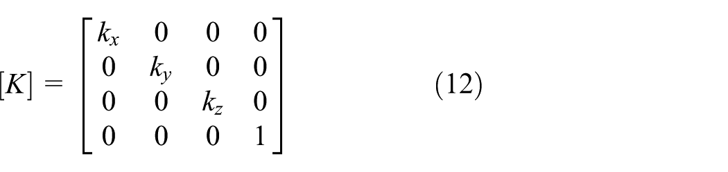
where

In order to analyze the influence of all variables on total force deviation, error sensitivities of all variables in
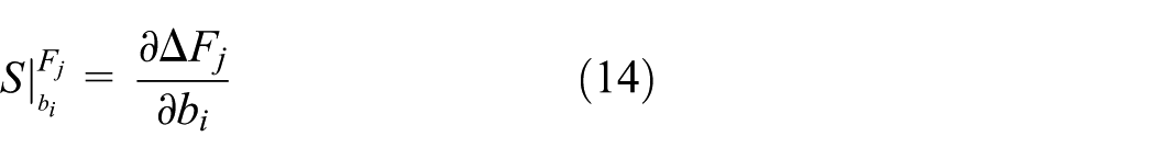
All the non-zero results are shown as follows
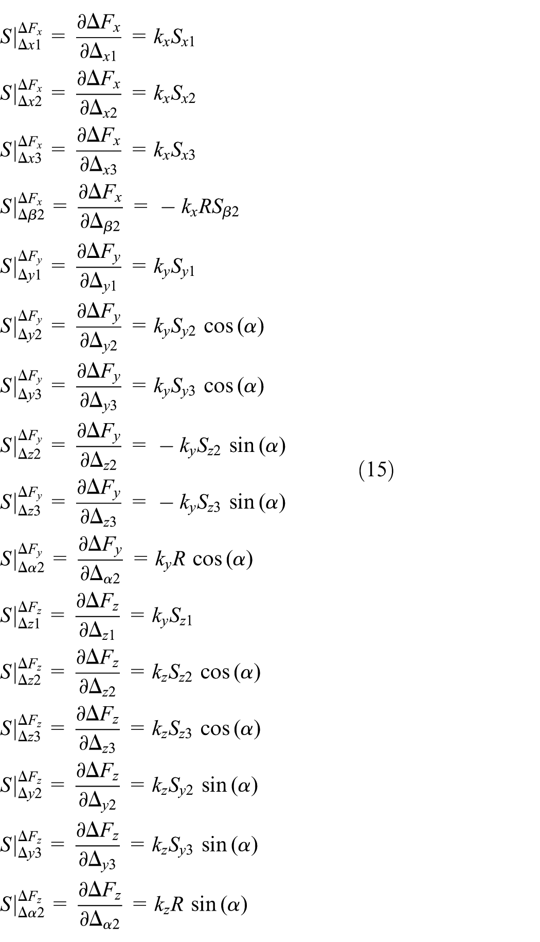
It is obvious that with restriction of self-alignment device,
Structure improvement of VFR system
Because the influence of force error, force deviation generates, which decreases output precision. Aiming at decreasing force deviation, paralleled supporting rod is put forward, in Figure 8. Paralleled supporting rod uses a structure of pillar through arc guide, arranged in left and right sides. The hole of arc guide restricts additional rotation of loading rod. Therefore, the rotation angle error can be decreased.
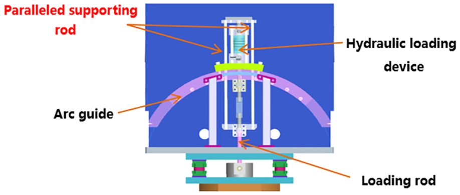
Structure improvement of VFR system.
Diameters of holes in arc guide and paralleled supporting rod directly influence force transfer process. Because hydraulic loading device in loading process produces straight-line movement, if there is contact between rod and hole, friction that decreasing measurement precision must generate. So there is a gap between rod and hole. However, if the gap is too large, restriction performance is lower. Synthesizing the statement above, clearance fit can be used in shaft-hole fit. Assuming radius of hole is larger than that of rod by

Assuming that
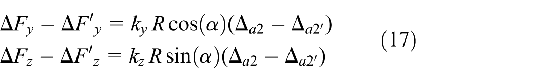
As shown in equation (17), if
Experiments and discussion
In order to investigate influence of forces with VFR on calibration and measurement precision, static calibration and VFR loading experiments are devised. Static calibration mainly utilizes hydraulic loading device to load three-directional forces and its performance can be accessed through the indices of nonlinearity and repeatability; simultaneously, sensitivities of sensors are obtained. VFR loading experiments mainly utilize VFR loading device to load force with VFR and ranges, investigating influence of ranges on sensitivities and VFR on measurement precision.
Orthogonal calibration experiments
VFR test system is shown in Figure 9. The whole system mainly consists of VFR test system, 12 charge amplifiers (Kistler 5018A), 1 data acquisition (Data Translation DT9804), a computer and software. Calibration system containing VFR loading device and lateral loading device can load 0–5000 N. Based on the positive piezoelectric effect, the dynamometer can produce induced charges caused by force, and the charges can be processed through the charge amplifier, data acquisition module, and computer to obtain the output voltages of the forces.
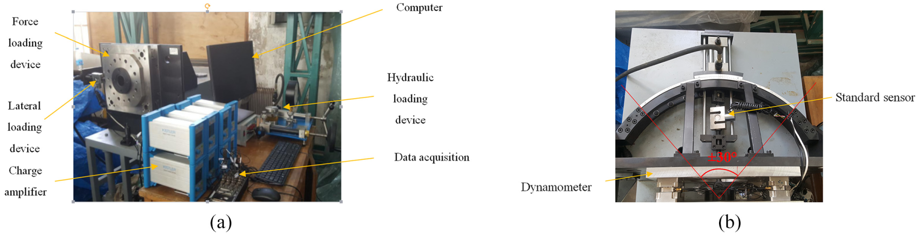
VFR measurement experiments: (a) experimental equipment and (b) VFR loading system.
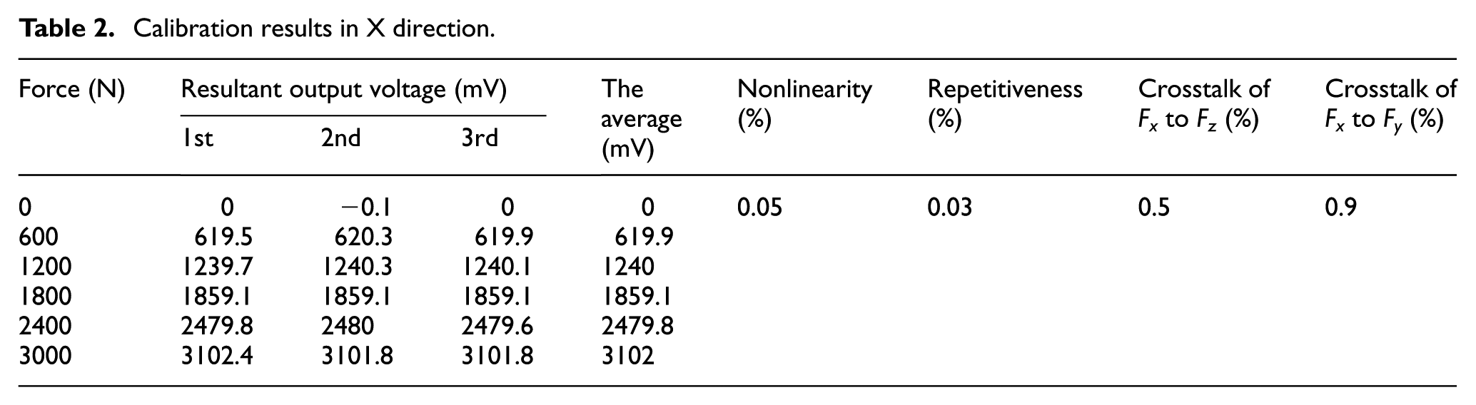
The resultant force employed for calibration of the VFR device was equal to 5000 N. Calibration mainly provides fundamental parameters like sensitivities for VFR experiments. Based on VFR measurement system, main forces are loaded in main direction. Hydraulic loading device was represented by the following values of 1000, 2000, 3000, 4000, and 5000 N. The sensitivities of charge amplifiers in Z directions are 4.00 and 8.00 pC/N in X, Y directions. Standard sensor is used to obtain the loading force in calibration. The sentivity of dynamometer can be fitted with the loading force and voltage outputs of dynamometer. Calibration results in three directions (X, Y, Z) are presented in Tables 1–3.
Calibration results in Z direction.

Calibration results in X direction.
Calibration results in Y direction.
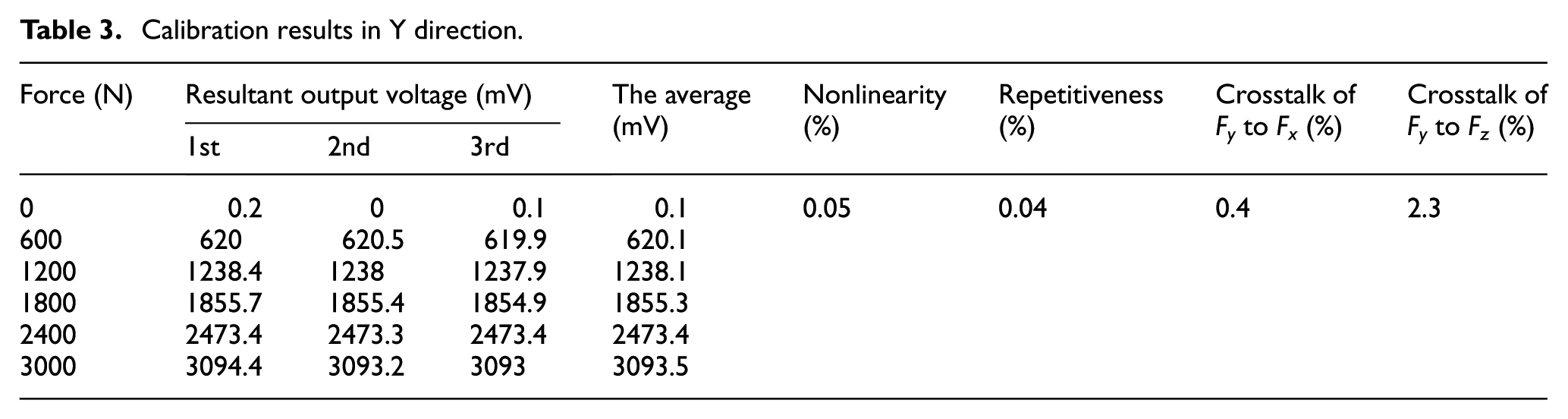
From Tables 1–3 and Figures 10–12, sensor’s outputs of three directions have correct indices. The nonlinearity in X, Y, and Z reaches following values of 1.95%, 0.05%, and 0.05%, respectively. Repetitiveness reaches following values of 0.06%, 0.03%, and 0.04%, crosstalks in three directions are less than 2.5%, meeting the measurement requirement.
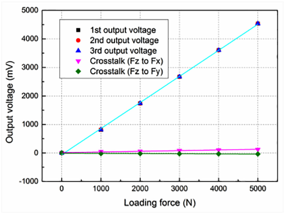
Force calibration curve in Z direction.

Force calibration curve in X direction.

Force calibration curve in Y direction.
VFR loading experiments
At 5000N-resultant force from 0° to 30°, VFR measurement system is used to load forces with VFR. Based on following requirements, force variation in main direction is relatively small (4330–5000 N), and calibration range is set as 5000 N. While force variation in Y direction is relatively big (0–2500 N), calibration ranges are set as 200, 500, 1000, 1500, and 3000 N and their sensitivities are determined in Figure 13.
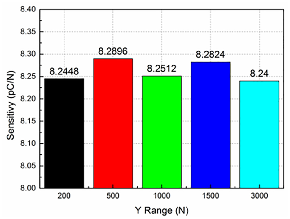
Sensitivities of different ranges in Y direction.
As shown in Figure 13, sensitivities’ fluctuation of different ranges in Y direction is very small, that is, the maximum difference is only equal to 0.0496 pC/N.
At resultant force of 5000 N, vector forces with force ratios of 28.63, 11.43, 5.67, and 1.7 are loaded with different angles of 0°, 2°, 5°, 10°, and 30° generated by hydraulic system. When the angles are 2° and 5°, force ratios are above 6, belonging to large force ratio loading; while the angles are 10° and 30°, force ratios are less than 6, belonging to small force ratio loading. The influence of different force ratios on measurement precision is investigated at different force ratios.
From Figure 14 and its data, measurement precision decreases with larger force ratios. As for large force ratio (loading angle of 2° and 5°), at loading angle of 2°, max. resultant deviation is 89.8 N (1.7% full of scale (FS)) and average deviation is 40.4 N (0.8% FS); at loading angle of 5°, max. resultant deviation is 106.3 N (2.1% FS) and average deviation is 46.3 N (0.9% FS). As for small force ratio (loading angle of 10° and 30°), at loading angle of 10°, max. resultant deviation is 88.3 N (1.8% FS) and average deviation is 51.1 N (1.0% FS); at loading angle of 30°, max. resultant deviation is 223.4 N (4.5% FS) and average deviation is 111.9 N (2.2% FS).
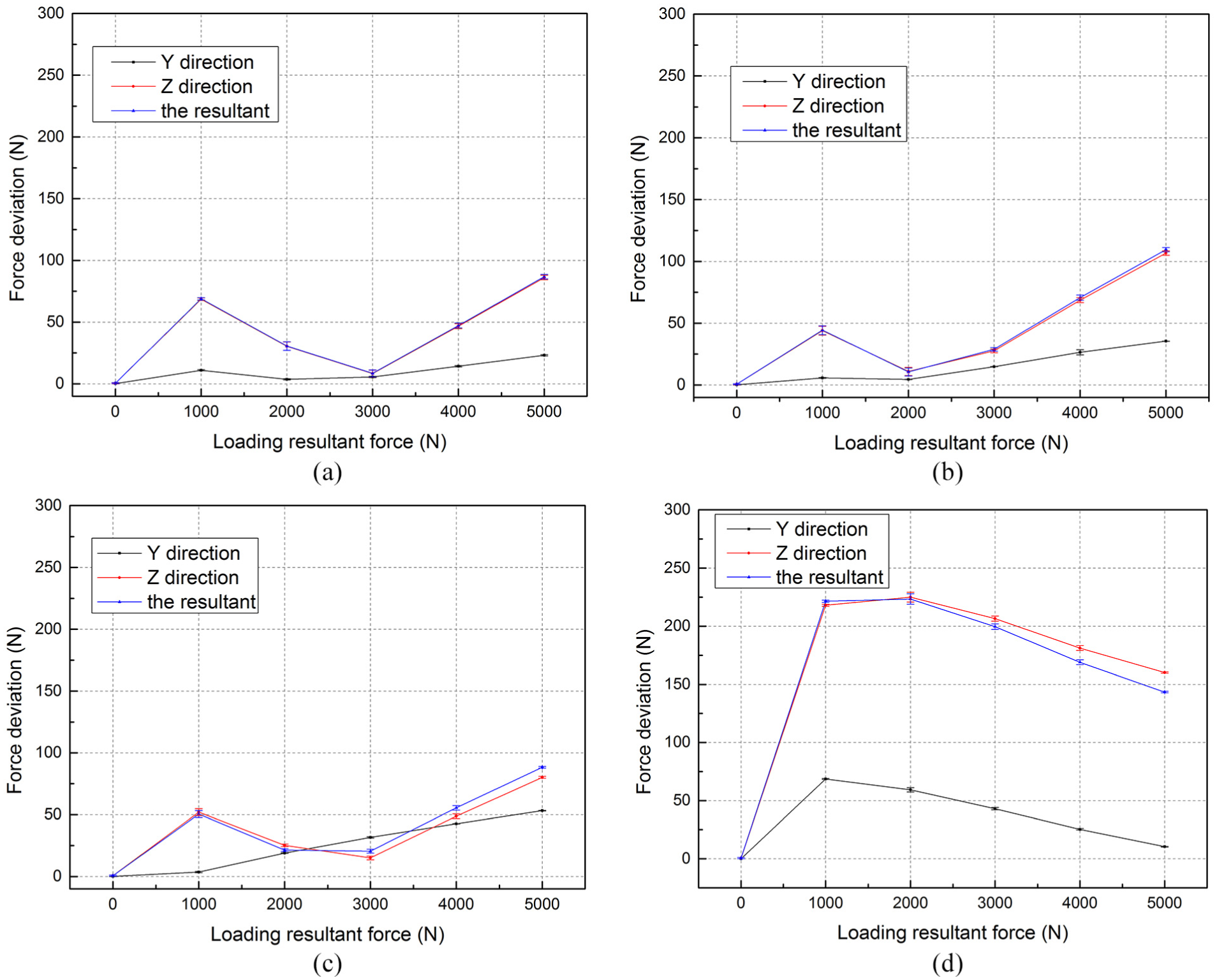
Force deviations in different force ratios: (a) 2°, (b) 5°, (c) 10°, and (d) 30°.
Dynamic calibration of test system
Sensors of different dynamic characteristics have a significant influence on the force parameters, so the dynamic calibration of sensors is particularly important. The common methods for performing dynamic test are frequency response method, step response method, and hammering method.
The hammering test method is fast, and test period is short. This method does not enable to follow the connection between incentive device and test structure. The test system shown in Figure 15 consists of dynamometer, hammer, charge amplifier (Kistler 5018A), data acquisition (Data Translation DT9804), computer, and software. The hammer is incentive device of the method, and it is composed of top hat, force sensor, and accessory. The magnitude of power is determined by percussion speed and quality of the accessory. Force sensor is stroked with a certain force, and then force sensor generates charges through the signal acquisition system into the computer. MATLAB is used for filtering analysis. The corresponding natural frequency curve is shown in Figure 16.
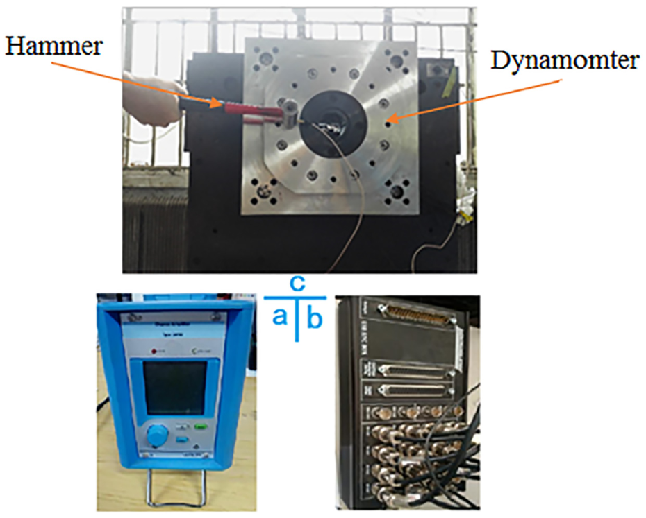
Dynamic structure of test system: (a) charge amplifier (pC/N), (b) data acquisition, and (c) test device.
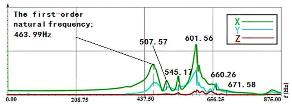
Frequency spectrum curve of test system.
It can be seen from Figure 16 that the system has the biggest amplitude in the X axis, and the Z axis has the smallest. The first natural frequencies of X, Y, and Z axes are 463.99, 470.01, and 545.17 Hz, respectively. The curve law of X axis direction and Y is roughly the same. The second and third natural frequency of X axis reaches the following values of 507.57 and 545.17 Hz at very small amplitude. When the frequency is lower than the fourth natural frequency of X, the amplitude of three directions is relatively mall. When the frequency increases, the amplitude of the three directions will become bigger. The fourth natural frequency of X axis and Y axis is 660.26 Hz, and at this frequency, the amplitude of X axis and Y axis reaches the maximum, but that of the Z axis is still small. The fifth natural frequency is 656.25 Hz; then the amplitude of Y axis is bigger than X axis. However, when the frequency is higher than 661.58 Hz, the X, Y, and Z axes are in the attenuation state. With the frequency increasing, the amplitude of the three directions decreases gradually until it is zero. It can be seen that the first natural frequency is high, and it is higher than the minimum test frequency (200 Hz), which can effectively avoid system resonance. In addition, when the frequency is low, the amplitude of the three directions is small, which has little impact on the experimental results, so the test result is more accurate and reliable.
Conclusion
In this article, VFR test system based on forces with variable-loading-angle characteristics is proposed. The conclusions are as follows:
Aiming at force vector loading demand with different force ratios, VFR loading device is designed, realizing force ratios of loading forces from 1.4 to theoretical infinity by changing loading angle.
In order to improve the loading accuracy at different force ratios, position errors and motion errors of key components in transmission chain are analyzed, and the error analysis of VFR loading device is completed. Paralleled support device is designed to reduce loading error, improving loading accuracy with different angles.
The orthogonal static calibration, VFR loading experiments are completed in VFR test system. The results in orthogonal static calibration show the main indices are less than 2%, verifying static performance of the system. The results in VFR loading experiments show that the overall average deviation is 2.2% FS, verifying high force measurement accuracy with VFR in the system.
The dynamic calibration obtains the first natural frequencies of test system in three directions of X, Y, and Z are higher than the lowest test frequency, showing good dynamic performance of the test system.
Our further research will concentrate on the improvement of force measurement precision with VFR.
Footnotes
Handling Editor: Michal Kuciej
Declaration of conflicting interests
The author(s) declared no potential conflicts of interest with respect to the research, authorship, and/or publication of this article.
Funding
The author(s) disclosed receipt of the following financial support for the research, authorship, and/or publication of this article: This project is supported by National Natural Science Foundation of China (grant nos 51475078 and 51675084), Aeronautical Science Foundation of China (grant no. 20160163001), and Fundamental Research Funds for Chinese Central Universities (grant no. DUT17GF211).