
Abstract
Multi-point forming uses forces applied to a tool, comprising of multiple pins set at different heights, to form sheet metal for panelling in white goods, automotive bodywork, aircraft frames and so on. The use of multiple pins allows for rapid change over and flexibility in the tool making it suitable for small-batch and prototype component manufacture. To explore the relationship between ‘springback’ of the sheet metal on release from the tool, and the applied pin force, it is first necessary to understand and measure the forming forces. This article presents a novel method of measuring forming forces on individual pins in a multi-point forming tool using fibre Bragg grating sensors, monitoring the elastic strain on the selected pins during the forming process. The operating principles behind forming force measurements using fibre Bragg gratings are introduced and a relationship is developed between springback in the formed part after the final unloading and the forming force as measured on selected individual pins under different compression ratios (30%, 40%, 50% and 60%) of the elastic cushion between the tips of the pins and the workpiece. Experiments were performed to validate the proposed measuring method, and results indicate that forming forces detected by the proposed method correlated well with the results obtained by numerical simulation. This suggests the proposed method has good potential for real-time measurement and monitoring of forming force distribution in multi-point forming tools during the forming process.
Introduction
Multi-point forming (MPF) is a kind of flexible metal sheet forming technique with reconfigurable dies for three-dimensional (3D) surfaces with low manufacturing costs compared with solid dies in industrial applications such as aerospace, architecture and automobiles.1–3 Figure 1 is a schematic diagram of an MPF tool. 4 This shows the pin matrices (MPF-Punch and MPF-Die), the elastic cushions and the workpiece (metal sheet) sandwiched between the elastic cushions. MPF technology was utilised for rapid fabrication of 3D sheet metal parts using two reconfigurable element groups with height-adjustable pins (continuous upper and lower solid dies).5,6 A multi-point matched-die forming technique and its typical applications were reported. 7 A flexible hybrid sheet forming process combining MPF and incremental sheet forming (ISF) was used for the control of the thickness of metal parts. 8
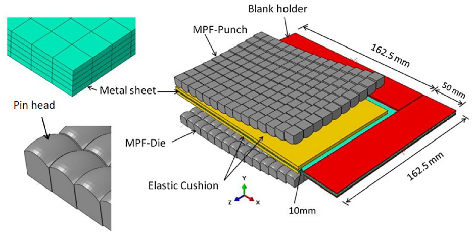
Schematic diagram of an MPF tool. 4
The MPF process parameters including the elastic cushion thickness, coefficient of friction, pin size and radius of curvature were investigated and optimised. 9 Springback is a common defect in sheet metal processes and needs to be minimised or compensated for, depending on part usage. 10 The forming parameters influencing springback in an MPF process were investigated by experiments and finite element simulations. 11 Numerical investigations of an MPF process were carried out, which covered wrinkling, dimpling and springback. 12 With individually controlled force-displacement, a new MPF process was presented to reduce springback. 13 The forming parameters such as the hardness and thickness of the elastic cushion, blank holder force, coefficient of friction and radius of curvature were investigated and optimised to improve the quality of parts using MPF. 14
Forming force measurements are essential for the investigations of MPF processes to avoid defects and improve forming precision. To detect forming forces on individual pins in MPF tools within a narrow working area requires sensors with high specifications. Fibre Bragg grating (FBG) sensors have a series of unique advantages over conventional electrical and piezoelectric sensors, including high precision, small size (125 μm diameter with cladding), lightweight, immunity to electromagnetic interference, distributed measurement and ease of installation.15,16 FBG sensing technology has found many uses in manufacturing and industry.17,18
FBGs can deliver sensitive and distributed strain and force measurements for different materials and structures.19,20 FBG sensors embedded into polymer composite materials were adopted for strain measurements. 21 An experimental method using FBGs for strain measurements of wooden structures was presented and validated. 22 FBG sensors were embedded in a 3D printed sensor structure for mechanical strain measurements. 23 FBG sensors were used for quasi-distributed dynamic strain measurement and strain modal analysis of hydraulic system pipelines.24,25 Embedded FBGs were used to monitor strain in aluminium alloys during production. 26 Multi-point strain measurement in an NbTi superconducting sample coil was carried out using FBG sensors at low temperature and in a high background magnetic field. 27 FBG sensors were used to measure strain and temperature induced during micro-turning operations. 28
Force sensitive forceps with an FBG sensor on the grasper were proposed for a surgical robot in a surgery environment. 29 A bolt force status monitoring method using FBG sensors was proposed for remote real-time monitoring of roadway anchorage engineering. 30 A FBG-based transverse force sensor was presented and experimentally demonstrated. 31 A method of measuring bending force and temperature was proposed. 32 A FBG six degree-of-freedom force-moment sensor was developed for a surgical robot 33 and FBG sensors were used to monitor inner forces of a reinforced concrete frame-shear wall structure. 34
The work reviewed above highlights the extensive use of FBG sensors in strain and force measurements. However, there has been no reported research into using FBG sensors in MPF tooling. The aim of this article is to present a novel method suitable for detecting and analysing real-time forming forces on individual pins in MPF tools. By measuring the forces on strategically located pins, the force distribution on MPF tools could be obtained to optimise MPF process parameters for springback reduction. The proposed measurement method uses FBG sensors to monitor the elastic strain on pins of MPF tools. The article is organised as follows: the ‘Operating principles of forming force measurement’ section introduces the operating principles of forming force measurement using FBG sensors. An analysis of forming forces on MPF tools using numerical simulations is described in the ‘Numerical simulation’ section. The ‘Experiment setup and results’ section reports on experiments to measure forming forces using FBG sensors. The ‘Conclusion’ section concludes the article and provides suggestions for further work.
Operating principles of forming force measurement
The operating principles of forming force measurement are investigated in this section. The sensing principle of FBG is introduced and the method of forming force measurement using FBG is outlined.
Sensing principle of FBG
FBG is a kind of distributed Bragg reflector (Bragg grating) built into an optical fibre. When light from a broadband source is incident on one side of the reflector, the inscribed Bragg gratings act as a mirror reflecting certain wavelengths while passing the rest. FBG sensors could be added to the surface of a pin to obtain real-time information on the strain on it.
The Bragg wavelength reflected by the grating

Both strain and temperature affect the Bragg wavelength, as both change the grating periodicity, the latter due to the thermal expansion/contraction through the thermo-optic and thermal expansion coefficients.
Thus, any change in the refractive index of the fibre grating and/or fibre grating periodicity will cause a change in the wavelength of the reflected light from

Expanding equation (2) as a Taylor series and taking a first-order approximation, then for a fibre with a coefficient of thermal expansion

where Δε is the change in strain of the optical fibre, and ΔT is the temperature change. Generally, the temperature of the environment remains more or less constant and temperature effects could be neglected during a quick measurement. Thus, any shift in the Bragg wavelength
Forming force measurement
The basic operation of forming force measurement as carried out on four individual pins is shown on a quarter of the 3D finite element model in Figure 2. A ‘smart’ sensorised individual forming force tool is constructed by installing an FBG sensor axially along the pin. Each FBG attached to each pin reflects with a different wavelength allowing real-time information on total change in strain to be obtained for that chosen pin.
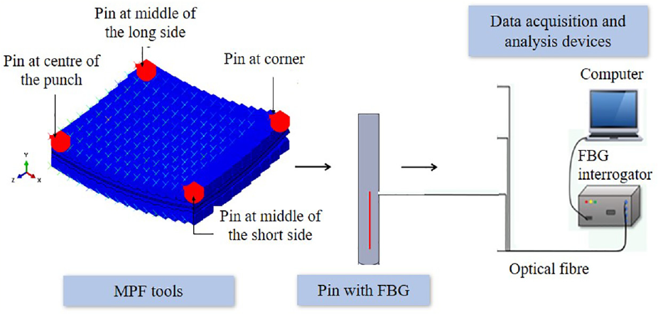
Measurement system for forming force on individual pins (quarter MPF tool).
The schematic diagram in Figure 2 shows the system used to measure forming forces of MPF tools (punch and die) including FBG sensors installed on the pins’ longitudinal surfaces, a data acquisition system and analysis devices. A multi-channel FBG interrogator is used to acquire the elastic strain change signals from the FBGs. The collected data for elastic strain is analysed and evaluated by a computer.
As shown in Figure 2, FBG sensors are attached to monitor the elastic strain of the four pins during sheet forming. The strain is proportional to the magnitude of the forming force. Assuming that temperature effects are negligible as the surrounding environment temperature is stable (ΔT = 0), equation (3) can be re-written as
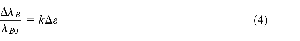
where k = (1 − pe) and pe = 0.22 (photo-elastic coefficient), then k = 0.78 × 10⁻⁶ με−1. Substituting these values into equation (4), we obtain
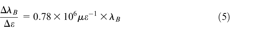
From equation (5), it can be calculated that when the FBG is strained by 1 με the reflected Bragg wavelength increases by 1.21 pm for an FBG with a centre wavelength of 1550 nm. 18 The initial wavelength of the sensor is known, and k is constant. The elastic strain (ε) on pins under the forming force could be calculated using equation (6)
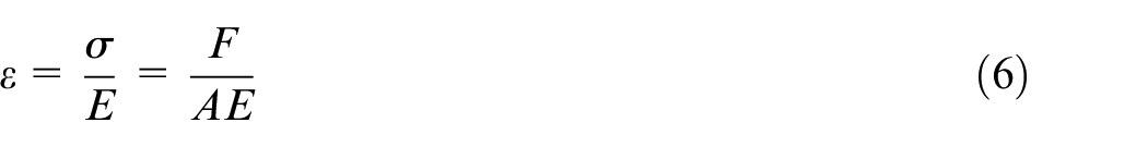
where F is the force on the pin, A is the cross-section area of the pin and E is Young’s modulus of the pin’s material. According to equations (4) and (6), the forming force on pins could be calculated using equation (7)
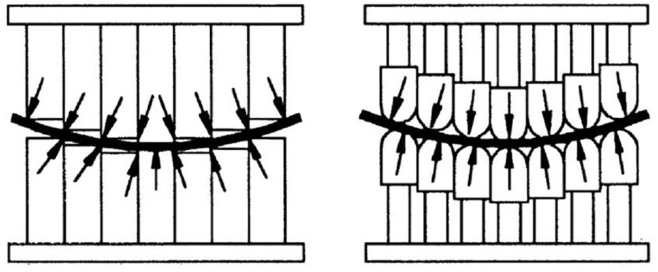
As shown in Figure 3, the forming force does not act vertically on every pin but depends on the pin’s position and shape. The forming force is vertical on the pins at the centre of the MPF tool, but it will gradually incline away from the vertical depending on the radius of forming curvature until, at the edges of the MPF tool, it reaches the maximum degree of inclination. Equation (7) could be applied to calculate the local force on the pin.
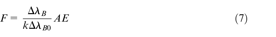
Different pin shapes with different force distributions. 37
For small values of radius of curvature (R ≤ 400 mm), the height difference between the pins is relatively large. In this case, the forming force distribution will be different from that for a large radius of curvature (R = 800 mm) because the difference between the pin heights is smaller, as shown in Figure 4. Consequently, at the end of the loading step, the values of the force on the same pin at the same position in the two cases will be different, as shown in Figure 5(a) and (b). The simulation results are for a 40% compression ratio of the same pin at the centre of punches with 800 and 400 mm radii of forming curvature.
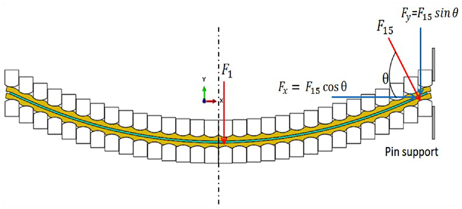
Force distributions on different pins (R = 800 mm).
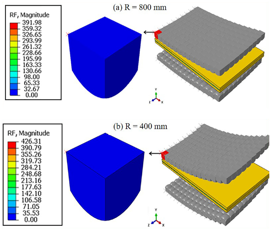
Forming force on a pin at the centre of the punch for different forming radii: (a) 800 mm and (b) 400 mm.
Figure 6 shows the simulated force results on the selected pins at different positions in the two cases. As the radius of forming curvature increases, the force distributions become uniform due to smaller differences between pin heights.
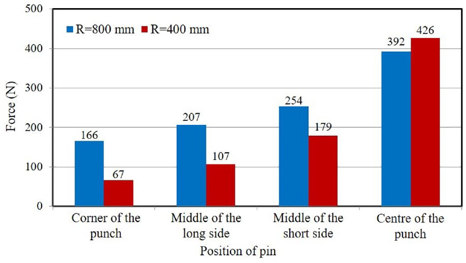
Forces on individual pins for different radii of forming curvature.
Numerical simulation
To verify the proposed method of forming force measurement on individual pins of MPF tools, numerical simulation (finite element analysis (FEA)) was carried out using ABAQUS software. Figure 7(a) shows the positions of selected pins in an MPF tool. Pin 1 is at the corner of the MPF tool where maximum springback occurs. Pins 2 and 4 are respectively situated in the middle of the long and short sides of the MPF tool with less springback. Pin 4 is located at the centre of the tool with minimum springback. The simulated results for springback at the end of the unloading step in an MPF process with 800 mm as radius of forming curvature are shown in Figure 7(b).
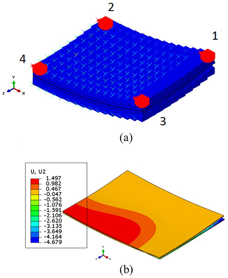
(a) Positions of selected pins and (b) simulated springback value after unloading for 40% compression ratio of elastic cushion.
Figure 8 shows the elastic cushion subjected to different compression ratios of its original thickness (3 mm). For example, 40% compression ratio of a 3-mm-thick elastic cushion means 0.4 × 3 mm = 1.2 mm and when the punch reaches the end of the forming distance, it will move downwards 1.2 mm. A general contact algorithm was used to model the interaction between the elastic cushion and the tips of the MPF tool. 1 Coulomb friction of 0.1 was used to model the contact between the elastic cushion and pins as well as the elastic cushion and sheet metal. The simulated forming forces on individual pins at different compression ratios of the elastic cushion are shown in Figure 9. It is clear that the force on the selected pins rises as the punch moves down and increases the compression ratio of the elastic cushion (30%, 40%, 50% and 60%) without causing dimpling of the formed sheet.
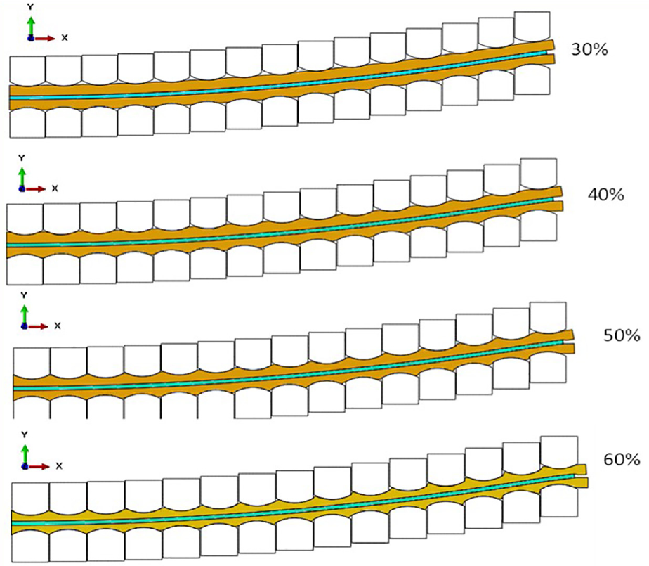
Simulation results for different elastic cushion compression ratios.
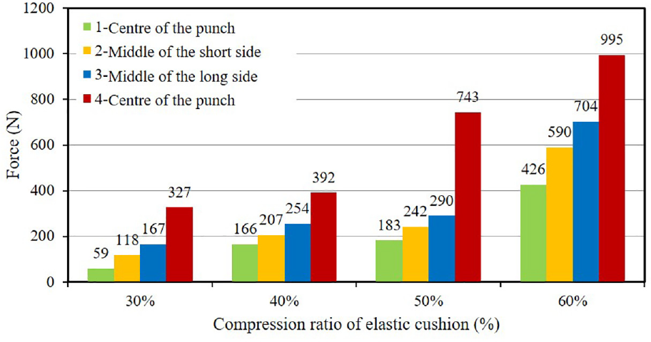
Forming forces on individual pins.
Figure 10 shows the relationship between springback of the final formed part (R = 800 mm) at the end of the loading step for different compression ratios of the elastic layer and the values of the forming force on the selected pins. For example, at a 30% compression of the elastic layer, the forming force on the pin at centre of MPF punch was over 300 N and springback more than 6.5 mm, while at 60% compression the force was nearly 1000 N and the springback approximately 5.0 mm.
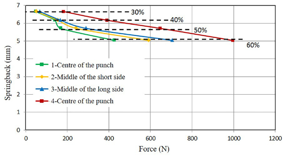
Springback versus force on different pins for different compression ratios.
There was a sharp increase in the force on the pin, as the space between the pin tips became filled with elastic material due to the increased compression ratio, see Figure 8. This caused more resistance to movement of the MPF punch. As a result, the local force increased and springback decreased.
Experiment setup and results
Static calibration
To obtain the sensitivity of the FBG sensors on the pins, static calibration experiments were carried out using the setup shown in Figure 11. A universal test machine from Instron was used to apply compressive forces on a pin fitted with an FBG sensor. The pin was secured on the workbench of the machine by a clamping vice. The forces applied on the pin changed from 0 to 10 kN in increments of 2 kN. A four-channel FBG interrogator (SmartScan from Smart Fibres Ltd,) 38 was used to record the wavelength changes of FBG sensors with a resolution of 1 pm and a maximum acquisition rate of 2.5 kHz per channel. The Young’s modulus of the pin material is approximately 200 GPa and the cross-section area of the pin is 10 mm × 10 mm. 39
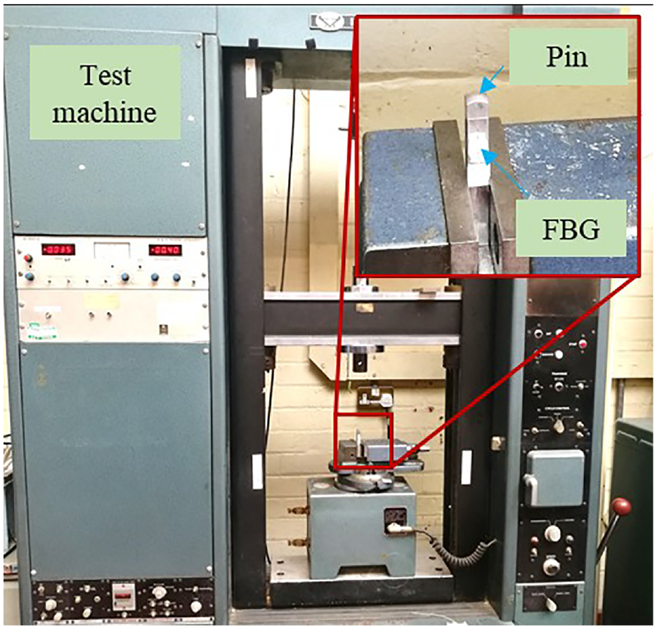
Experimental setup of static calibration.
Figure 12 illustrates the wavelength shift of the FBG versus the compressive forces on the pin. The experiments ware repeated six times with the force being increased and then decreased to demonstrate the repeatability of the FBG sensor, as shown in Figure 12(a). Figure 12(b) shows the average wavelength shift versus force. The relationship between wavelength shifts and force is given by equation (8) which was obtained by linear fitting

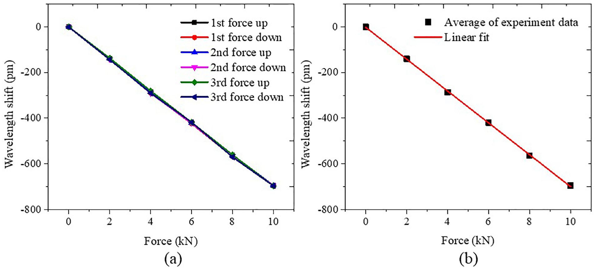
Static calibration results: (a) wavelength shift of the FBG versus the compressive force and (b) average wavelength shift versus force.
The force sensitivity of the FBG sensor is −69.7 pm/kN and the fitting linear correlation coefficient is 99.97%. The force sensitivity of the FBG sensor is −60.5 pm/kN calculated from equation (7).
Forming force measurement
Experiments were carried out to test the proposed ‘smart’ way of forming force measurement on pins of MPF tools. Figure 13 shows the experimental setup including an MPF tool installed on a 200-tonne Mackey Bowley press, FBG sensors, an FBG interrogator and optical fibres.
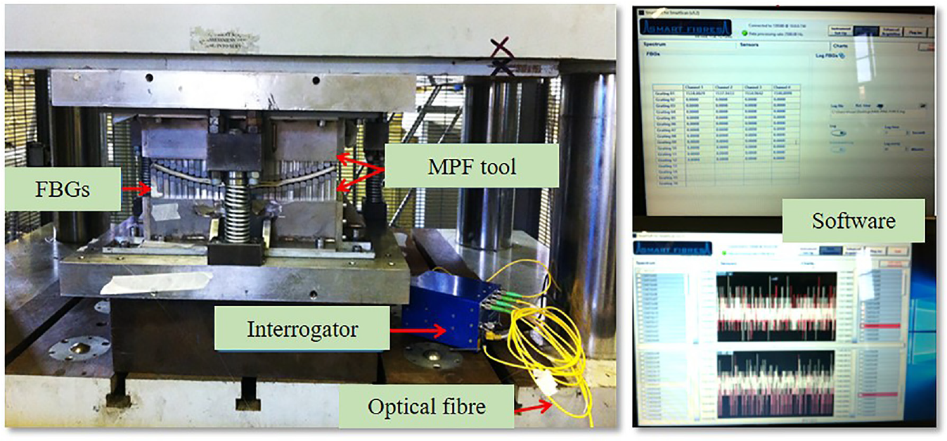
Experimental setup of forming force measurement.
Figure 14 shows the locations of the selected pins on the MPF tool. Each candidate pin used to measure the forming force was fitted with an FBG sensor. Before the bonding of the FBG sensors to the pins, it was important to prepare the pin’s surface to avoid introducing measurement errors such as strain transfer between compressed pin and FBG sensor. The press was adapted for loading the MPF tool to form sheets of 1.2 mm thick in aluminium alloy O-5251, with a radius of forming curvature of 800 mm. For this operation, springback on the final formed part was large.
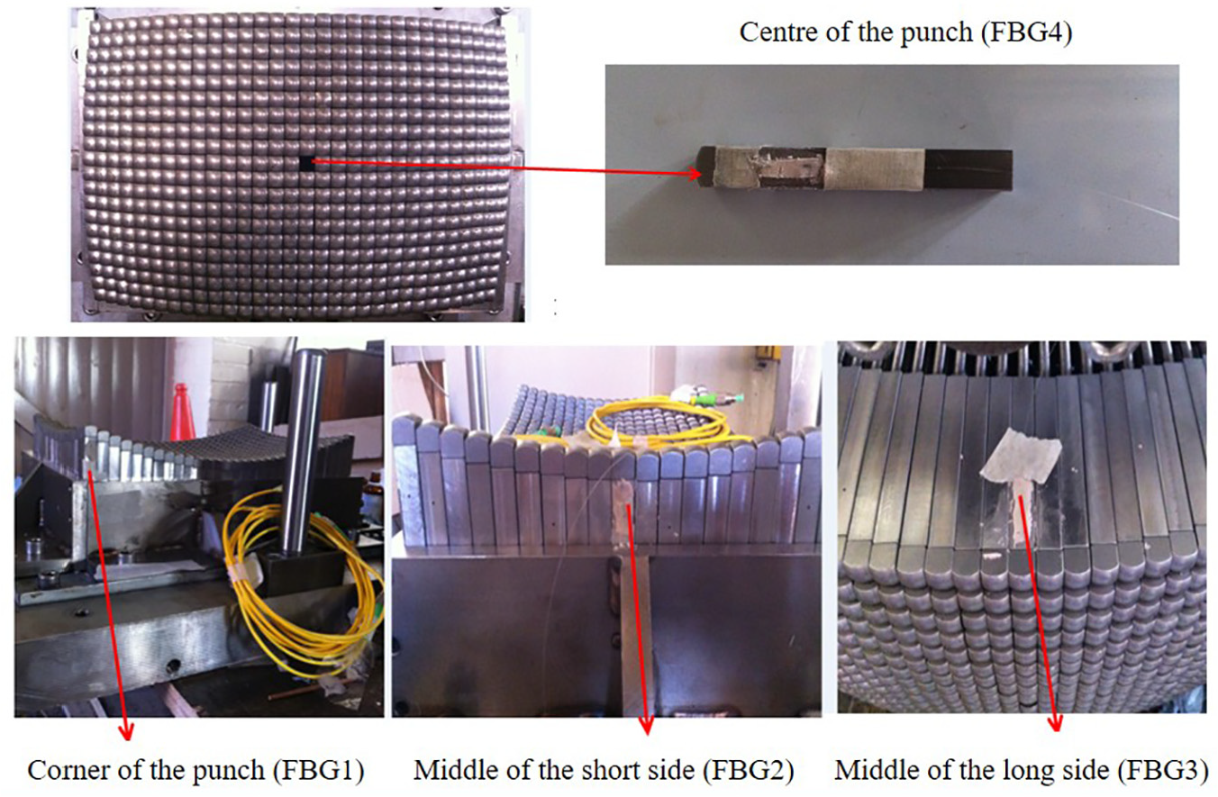
Locations of selected pins on MPF tool.
The wavelength changes and forming time histories were recorded for all four pins during the forming process. As an example, data collected for FBG4 on the pin at the centre of the punch is shown in Figure 15.
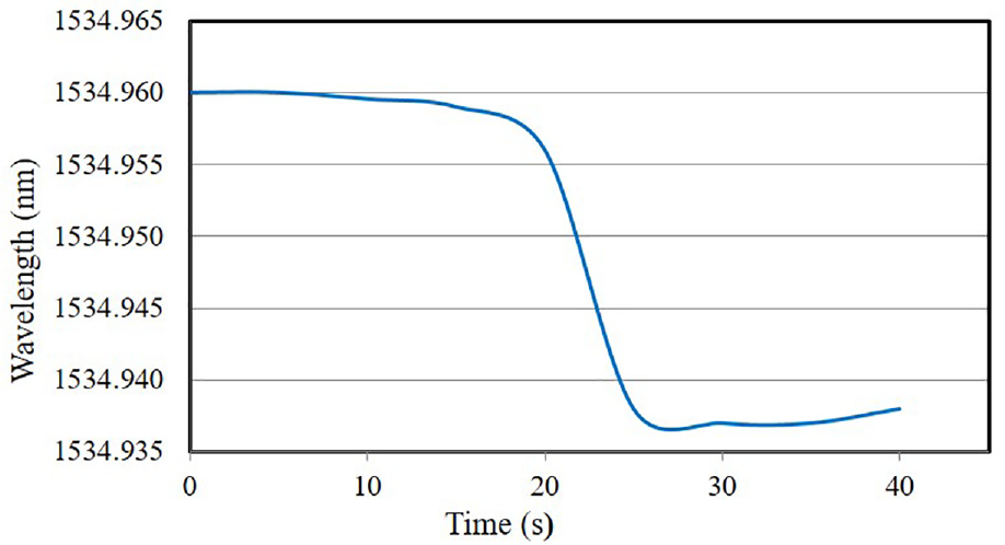
Wavelength shift of FBG4 versus time on the pin at the centre of MPF punch.
For the first 5 s, the movement of the punch takes up the slack in the system and no change in wavelength is observed. As the punch continues to move down, it starts to compress the elastic cushion, and from about 5 s to about 17 s, the wavelength of the FBG changes as the cushion is increasingly compressed (see Figure 7). At about 17 s, the rate of decrease in the FBG wavelength rises significantly as the forming process starts. The sharp fall in wavelength continues until at about 25 s the wavelength plateaus due to the compression strain in the pin at the end of the forming process. At about 40 s, the load is released.
As previously mentioned, the sensitivity of the FBG sensor is typically 1.2 pm/με. Table 1 lists the extracted wavelengths of FBGs at several time points in the forming process. According to equation (7), the maximum forces on each pin can be calculated using the data in Table 1, as shown in Figure 16. In order to evaluate the measurement accuracy of the forming forces on the pins, a comparison between the simulated and measured forces for each pin is shown in Figure 17.
Wavelength changes of FBG sensors under forming force.
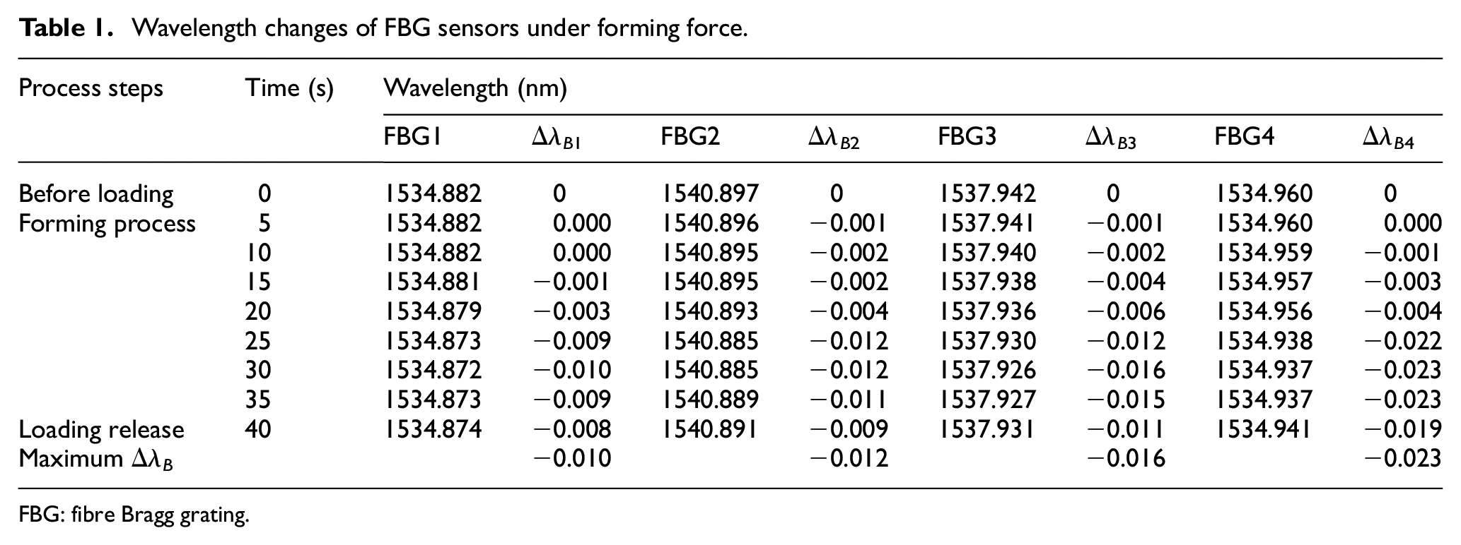
FBG: fibre Bragg grating.
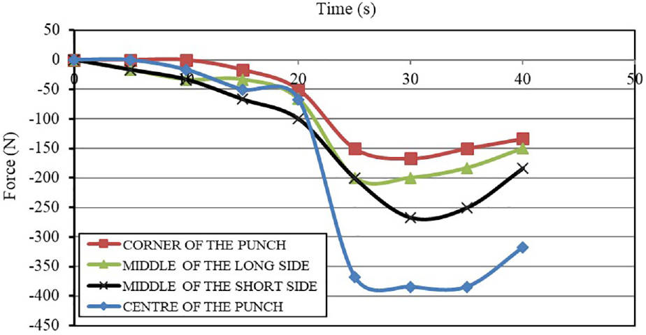
Force–time curve for different pin locations.
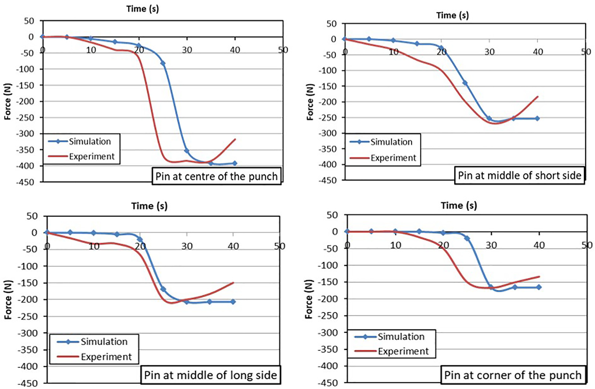
Comparison between simulation and experimental force trends for selected pins.
Also, the numerical error has been calculated as below

Figure 18 shows that the numerical errors are small, which indicates that the proposed measurement method was able to measure forming forces accurately.
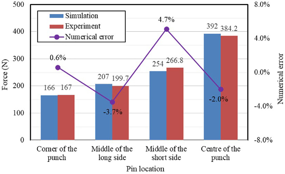
Validation of simulated forming force for radius of forming curvature 800 mm.
Conclusion
In this article, a method of forming force measurement in MPF tools using FBG sensors has been presented and validated for the first time. FBG sensors were used to measure the forming force on individual pins by monitoring the elastic strain in the forming process. The operation principle of the proposed measurement method was introduced. The article investigated the effect on springback of forming radius curvature and the forming force on selected pins. Experiments were carried out to validate the measuring method. Experimental results show that forming forces measured by the proposed method are in good agreement with those obtained by numerical simulations. The proposed method offers a good solution to measure or monitor forming force distribution on individual pins of MPF tools. Future work will focus on temperature compensation for the proposed forming force measurement method to increase its accuracy.
Footnotes
Declaration of Conflicting Interests
The author(s) declared no potential conflicts of interest with respect to the research, authorship, and/or publication of this article.
Funding
The author(s) disclosed receipt of the following financial support for the research, authorship, and/or publication of this article: This research is supported by the Engineering and Physical Sciences Research Council (EPSRC) and Innovate UK (Grant EP/L505225/1).