
Abstract
The present article highlights the acoustic waves scattering in a trifurcated waveguide containing compressible fluid together with step discontinuities and change of bounding material properties. The study is important because of its applications in active noise control measures, especially used to control the low-frequency noise and related vibrations. The governing boundary value problem is solved by using the mode-matching technique. The solution is developed for the analysis of symmetric, uniform, and non-uniform cross-sections. The solution procedure begins by determining the expanded form of field potentials in various duct regions of the waveguide. Then, the pressures and the normal velocity modes across the waveguide regions are matched at interface. The energy flux against frequency and various duct configurations is plotted. The solution is validated altogether through the apposite analytical and numerical results.
Introduction
Over the years, a range of interesting and challenging problems that involve the wave scattering analysis in bifurcated and trifurcated waveguide channels have been discussed by many researchers. The interest to minimize the noise pollution impending from the heating, ventilation, and air conditioning (HVAC) system of buildings or automotive exhaust systems of vehicles or aircrafts has stipulated the continued interest. The dissipative silencers containing complex geometrical shapes and bulk reacting materials have been modeled to attenuate the broadband noise. Several analytic and numerical techniques have been developed so far to incorporate these theoretical models. The aim of these studies was to investigate the sound attenuation region against various configurations of channels and material properties.1–5
The reduction of unwanted noise through the parallel plate setting of walls together with rigid, soft, or impedance type bounding characteristics has been discussed by many authors. For instance, the studies6–11 include the acoustic scattering in planar trifurcated waveguides containing rigid, soft, or porous lining along with stationary and moving compressible fluid medium. In all such cases, the duct segments contain constant geometrical and physical properties for which the single field representation remains suitable. The integral formulation based on Fourier analysis yields the Wiener–Hopf (WH) solution of the problems. But for more complex geometrical and physical properties, where the wave number spectrum in the waveguide is not continuous, the use of WH technique is not appropriate. However, recently the mode-matching (MM) technique has been used to deal with more complex geometries along with different medium and material properties. Such methods were initially developed to tackle canonical problems represented by Laplace or Helmholtz equations and the ducts/channel boundaries depicted by Dirichlet, Neumann, or Robin conditions. The investigation of reflection and transmission of waves across the interface at discontinuities in pipes and ducts is hence performed generally by matching modes, for example, see literature.12–15
The fundamental interest of the present study is to apply the hybrid matching scheme to analyze the acoustic scattering in non-uniform and/or uniform trifurcated waveguide that contains compressible fluid in its duct sections and different bounding wall conditions. For the duct region of constant physical and geometrical properties, the modal field representation is formulated. The key challenge is to encounter the geometric discontinuities at the plane connection (junction) of duct segments. The study of acoustic radiation from structural discontinuities goes back to Rayleigh 16 even though traditionally it has been merely feasible to look at rather a simple non-uniform geometry with modest dimensions. However, Boström, 17 Miles, 18 and, more recently, Nawaz and Lawrie 19 and Nawaz et al. 20 discussed the sound scattering from structural discontinuities together with obstacles at finite junction. The continuity conditions of pressures and normal velocities at aperture are used to match the scattering modes. The geometric discontinuities are encountered in normal velocity fields and many modes are allowed to propagate.
Here, the MM scheme has been explored to solve a trifurcated waveguide problem involving geometric discontinuities. The inside of the waveguide regions contains compressible fluid and different bounding wall conditions. Whereas Hassan 21 and Hassan et al.22,23 applied the MM technique to discuss the acoustic scattering in planar trifurcated and pentafurcated waveguide containing compressible fluid in the absence of step discontinuities. The physical problem is stated in the ”Mathematical formulation” section. The MM solution is sorted in the “MM solution” section. The energy conservation has been analyzed in the “Energy balance” section, while the numerical results and discussion is given in the “Numerical results and discussion” section. The concluding remarks are given in the “Conclusion” section.
Mathematical formulation
To formulate the boundary value problem, we consider an infinitely stretched trifurcated waveguide occupying the regions
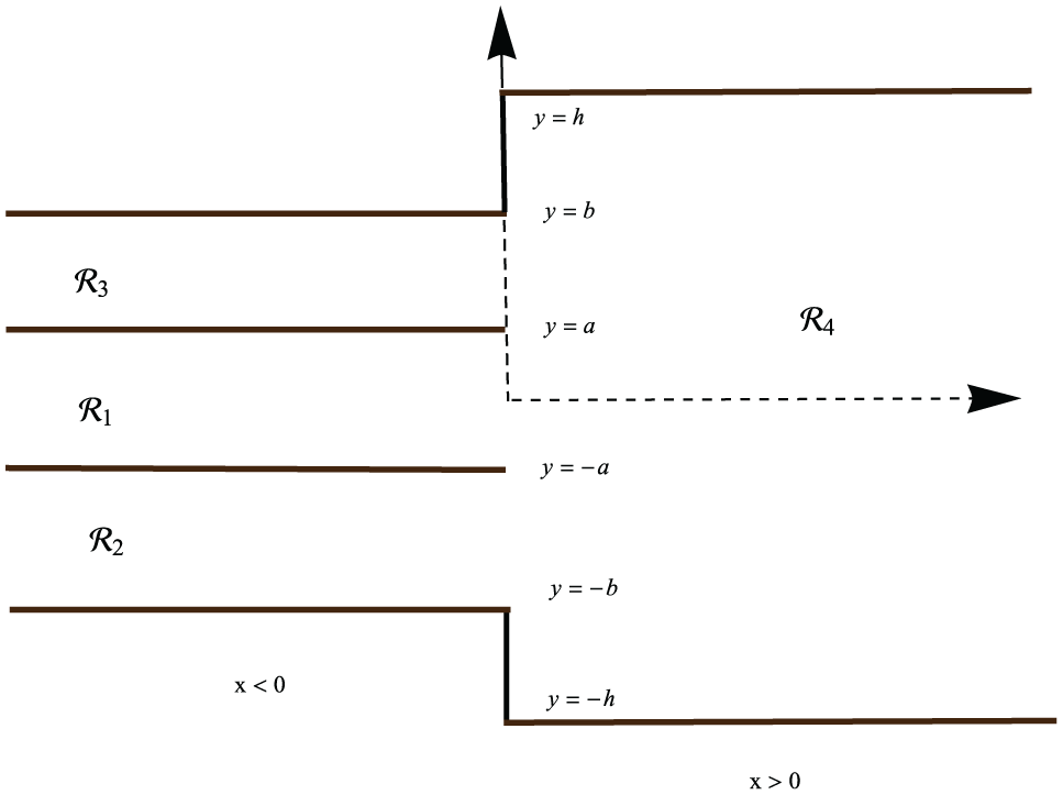
The physical configuration of the waveguide.
Consider an incident wave of harmonic time dependence propagating in

Now, we assume the harmonic time dependence of

In

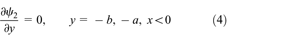

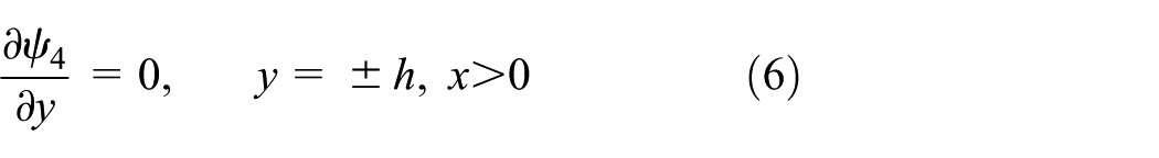

Here, equation (7) represents the rigid conditions for two vertical step discontinuities. However, the acoustically soft wall conditions for


Moreover, the continuity conditions of the fluid pressure and normal velocity at matching interface are


and

The subscript x here denotes differentiation with respect to x. In the following section, we solve the boundary value problem by using the MM technique.
MM solution
In order to solve the boundary value problem by using the MM technique, we first determine the eigenfunction expansions and related orthogonality conditions in each duct region. In different duct regions, these are found as

In this region, equations (2) and (3) yield the eigenexpansion form of field potential as

The quantity

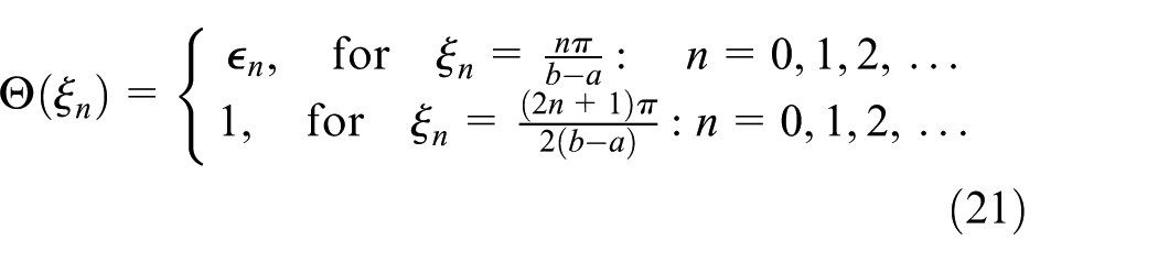
The corresponding eigenfunctions

where

From equations (2), (4), and (8), the eigenexpansion form is obtained as

where

However, for soft boundary condition at

The corresponding eigenfunctions

where

From equations (2), (5), and (9), the eigenexpansion form is found to be as

where

whereas for the soft surface at

The corresponding eigenfunctions


From equations (2) and (6), the eigenexpansion form of transmitted field is revealed as

where

The corresponding eigenfunctions

Now, the unknown coefficients

On multiplying equation (29) with

where


On using equations (17) and (26) into equation (10), we get

On multiplying equation (33) with

For all rigid–rigid cases

where

For all rigid–soft cases
where
On using equations (22) and (26) into equation (12), we get
On multiplying equation (39) with

For all rigid–rigid cases

where

For all rigid–soft cases

where

Now, to determine the transmitted mode coefficients, we use equations (17), (14), (22), and (26) into equation (13) to obtain

On multiplying with

Now, by means of equations (30), (34), and (40), it is straightforward to obtain equation (46) in terms of unknown

In this way, equation (47) leads to a system of infinite equations in which
Energy balance
The energy flux/power inside the duct regions in terms of non-dimensional time harmonic fluid velocity potential is defined by

where superscript asterisk (*) denotes the complex conjugate. From the definition of energy flux/power, the incident power is found to be


and

Now, it is important to note that the power fed into the system will be equal to the sum of scattering powers in different duct regions, that is

which is conserved power identity. For analysis purpose, we may scale the incident power at unity. For this, we divide equation (53) by a to get
Numerical results and discussion
Here, we truncate the system of equations defined by equation (47) up to N terms and then solve the retained system numerically to discuss the radiated energy flux/power in duct regions and to reconstruct the matching conditions at interface. Here, two types of bounding wall conditions for regions
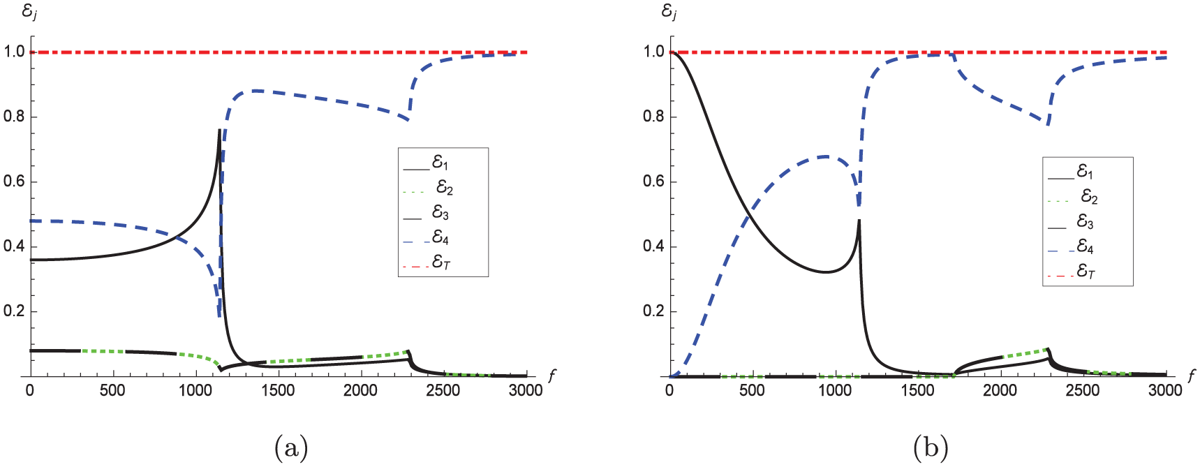
The energy flux/power components against frequency in discontinuous waveguide, with (a) rigid–rigid and (b) rigid–soft boundaries, where

The energy flux/power components against frequency in planer waveguide, with (a) rigid–rigid and (b) rigid–soft boundaries, where

The energy flux/power components against height discontinuities h, for (a) rigid–rigid and (b) rigid–soft boundaries, where
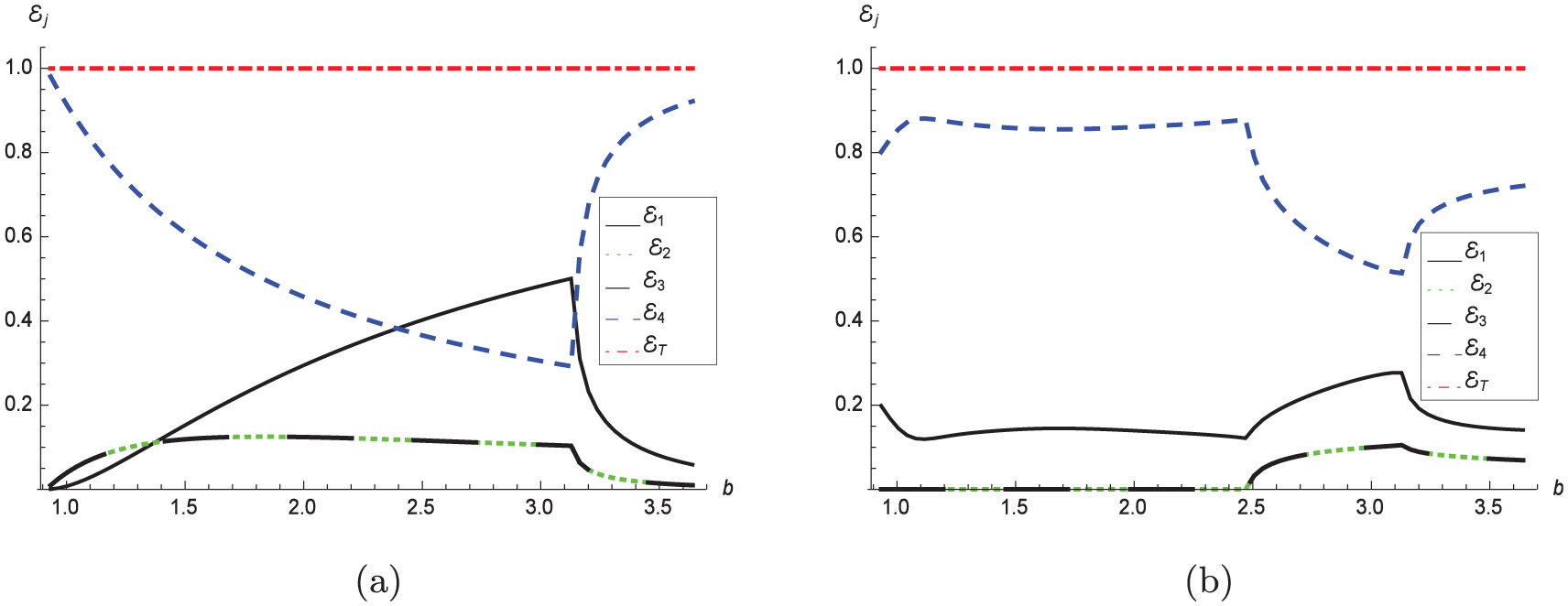
The energy flux/power components against b, for (a) rigid–rigid and (b) rigid–soft boundaries, where
The radiated power in different duct regions against frequency from
Note that the radiated energy against frequency depicted in Figure 2 contains sharp edges and the variation in radiated energy is more noticeable before and after these edges. These edges basically specify the cut-on position of duct modes. For the structural discontinuity case along with rigid bounding characteristics (Figure 2(a)), the two duct modes are cut-on at
In the next figure (Figure 3), we assume the planar waveguide configuration (without structural discontinuity) by taking
The effect of variation in symmetric height discontinuity on radiated energy is plotted in Figure 4. For the fixed frequency
Figure 5 shows the radiated energy in the planar waveguide against the size of the regions
By comparing all these four graphs, it is clear that the geometric discontinuity and the change of bounding material properties greatly affect the radiated energy duct modes, especially in low-frequency regime
Now, the continuity conditions of pressure and normal velocity are pieced together at interface to validate the truncated solution. Only the results for all rigid setting of waveguide along with height discontinuities are shown in Figures 6 and 7. The vertical dimensions of symmetric waveguide are fixed at
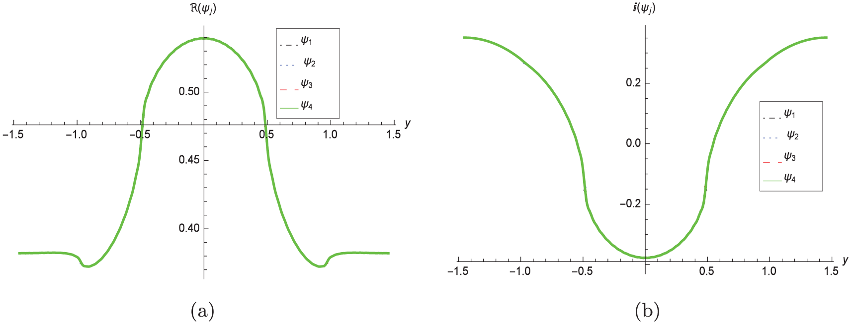
The (a) real and (b) imaginary parts of pressures against duct heights, at interface, with step discontinuities and rigid–rigid boundaries, where
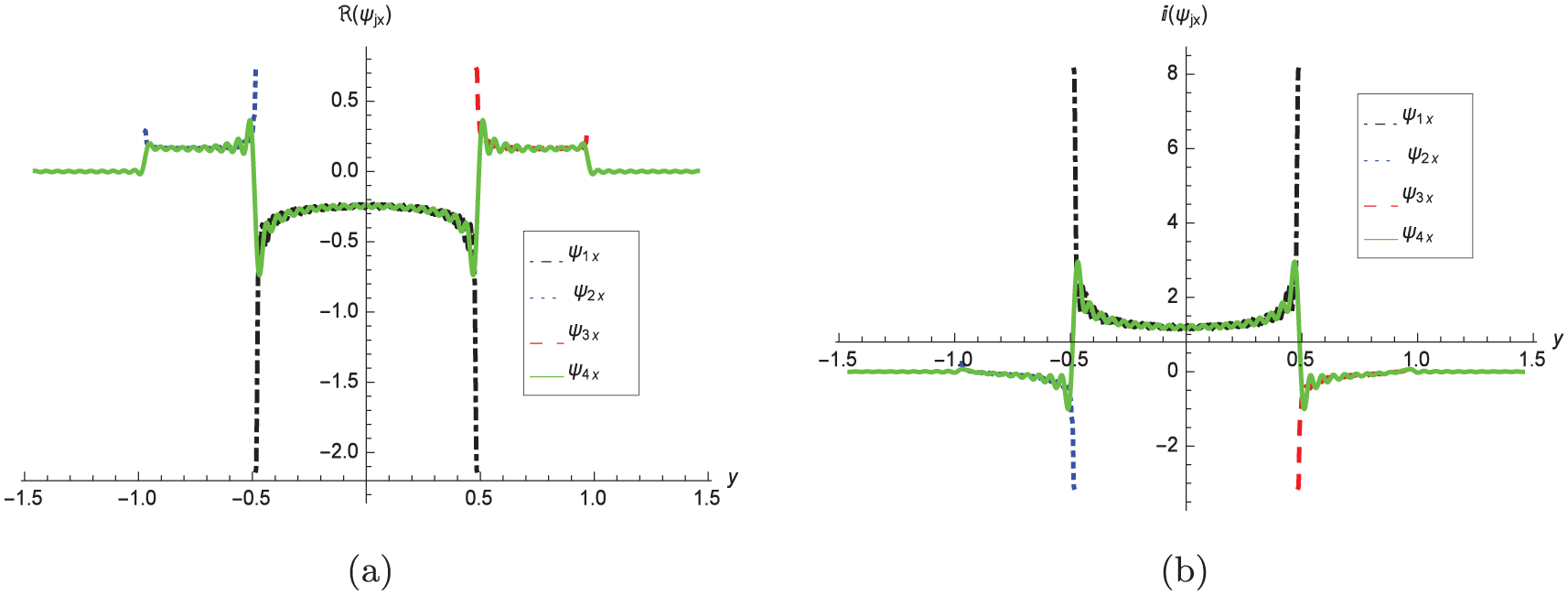
The (a) real and (b) imaginary parts of normal velocities against duct heights, at interface, with step discontinuities and rigid–rigid boundaries, where
In this way, the truncated solution reconstructs successfully the matching conditions of pressures and velocities at interface (see equations (11)–(13)). However, there appear some oscillations in normal velocity curves, which lessen on increasing the number of modes. One more physical check on accuracy of the truncated solution is the validation of conserved power identity
Conclusion
In this study, we have discussed the acoustic scattering in a trifurcated waveguide involving structural discontinuity at interface. The inside of the duct regions contains compressible fluid while the bounding wall conditions are chosen to be acoustically rigid and/or soft. By varying inside and bounding characteristics of the regions, two physical problems are formulated together. The MM technique has been explored to solve the envisaged boundary value problems. The eigenfunctions along with the appropriate orthogonality characteristics in their respective regions enable to recast the differential system into linear algebraic system. This system is then truncated and solved numerically. The provided solution remains valid for both discontinuous and planar waveguide structures. It also helps us to discuss the radiated energy against the variation of the geometric discontinuity and the size of the regions. The opposite numerical results are depicted in Figures 2 to 5. This problem can be regarded as a prototype that provides a benchmark scheme to model and solve a range of bifurcated or trifurcated waveguide problems involving geometric discontinuities and various material properties of medium and bounding walls.
Here, it is interesting to notice that the conservation of energy flux across the duct regions not only confirm the propagation of cut-on duct modes in various duct sections but also provide a useful check on the accuracy of algebra. Besides this, the truncated solution has also been used to reconstruct the matching of pressure and normal velocity modes at interface (see Figures 6 and 7). The validation of matching condition at interface along with the conservation of energy flux across the duct regions substantiate the MM solution altogether.
Footnotes
Handling Editor: Bo Yu
Declaration of conflicting interests
The author(s) declared no potential conflicts of interest with respect to the research, authorship, and/or publication of this article.
Funding
The author(s) received no financial support for the research, authorship, and/or publication of this article.