
Abstract
Stick–slip vibration is common in the oil well drilling process and is detrimental to down-hole equipment and drilling efficiency. In recent years, a new type of drilling technology, torsional impact drilling, has been developed to mitigate the stick–slip phenomena, particularly in the drilling of deep or abrasive formations. With this drilling technique, high-frequency torsional impacts are generated and applied to the drill bit, providing the drill bit with auxiliary energy. By mitigating or suppressing the stick–slip vibration, part of the energy wasted as a result of vibration can be regained. However, the effect of these impact loads on the dynamic response of a drill string in a stick state is unknown. In order to address this issue, a continuous system model of a drill string that includes torsional impact load was constructed. In the model, a Fourier series approach was used for the impact load, and the mechanical model was resolved with the mode superposition method. Case studies were done to understand the drill string dynamics, with and without the impact. The case study results demonstrate that high-frequency torsional impacts have little influence on the dynamic response of a drill string in a stick state.
Introduction
Friction-induced stick–slip vibration decreases the performance and safety of operation in a wide range of engineering problems, such as machine tool sliding 1 and squealing brakes. 2 In these systems, the combination of friction and movement can lead to system failure. The stick–slip vibrations of these systems are not the same because of differences in the motion characteristics and operating environment. The stick–slip vibration of a drill string is considered the most detrimental type of torsional vibration, for drilling equipment and drilling efficiency. 3
A major cause of deterioration of normal drilling performance is that a bit can stop rotating, as a result of encountering a tough formation, while the attached drill string continues to rotate. The torque that is applied through the drill string eventually succeeds in breaking the bit free, but the sudden release of the bit causes it to rotate faster than the drill string. 4 Cyclic stress is generated because of the alternation between the stick phase and slip phase, and this leads to fatigue problems in the drill string. 5 In addition, the high bit speed in the slip phase can excite severe axial and transverse vibrations in the bottom hole assembly, which may cause bit bounce, excessive bit wear, and a reduction in the rate of penetration.6–8 Figure 1 shows bit damage caused by stick–slip vibration.9,10

Previous work has investigated the suppression of stick–slip vibration in a drill string. Yigit and Christoforou 11 studied the effects of varying operating conditions on stick–slip and bit-bounce interactions and showed that the bit-rock contact conditions are a major influence on drill string dynamics. However, suppressing stick–slip vibration with active rotary table control approaches may not be effective because of the uncertain nature of the contact conditions. Utilizing modeling error compensation techniques, Puebla and Ramirez 12 presented a robust model-based feedback control scheme, to control stick–slip vibrations in oil drill strings. When the bit velocity and weight on bit (WOB) are used as variables that can be manipulated, stick–slip vibration can be suppressed via a decentralized control approach. Karkoub et al. 13 applied a control design technique known as µ-synthesis to study the problem of suppressing stick–slip vibration of the drill string. Zribi et al. 14 studied the problem of suppression of stick–slip vibration in oil well drill strings using the backstepping technique, to design control schemes for the system. Simulation results indicated good performance of the two controllers. Generally, for these studies, the most common approach to eliminating the stick–slip phenomena is reducing the WOB or increasing the rotary speed. However, these methods are not workable for a drilling application, because they usually lead to a decrease in drilling efficiency.15,16 For example, reducing the WOB may mitigate the stick–slip vibration as well as the bit bounce, but the possibility of decreasing the penetration rate is enhanced.17,18 Increasing the rotary table velocity may mitigate or suppress the stick–slip phenomenon, 19 but it may aggravate existing vibrations (e.g. lateral vibration) or trigger other types of vibration. In addition, some high-performance active control methods may be too expensive. 8
To address these issues, many new drilling technologies and drilling equipment have been developed, such as rotary percussive drilling. 20 Recently, a new type of drilling technology, torsional impact drilling,21–23 was introduced to mitigate the stick–slip phenomenon, particularly in the drilling of deep or abrasive formations. Field applications showed that the use of high-frequency torsional impacts (HFTI) can be effective in eliminating stick–slip and improving drilling efficiency. It is reported that in a field application in Western Oklahoma, an average of four trips and 12 days were saved, resulting in a total saving of US$763,000 for the drilling company. 24 In this drilling technique (as shown in Figure 2), a torsional impact generator is added to the drill string, directly above the drill bit. Torsional impact loads are generated and applied to the drill bit, providing the drill bit with auxiliary energy. The work of Tang et al. 25 provides details of the device and demonstrates that the HFTI can mitigate or eliminate stick–slip vibration. Even if stick–slip vibration remains when the high-frequency torsional drilling technique is applied, the amplitude of the vibration is reduced. By mitigating or suppressing stick–slip vibration in the drilling process, part of the energy that is wasted owing to vibration can be regained.

Schematic representation of a drilling system with a torsional impact generator.
For a drill string, encountering serious vibration is common during the drilling process. The impact generator, however, provides the drill string with impact loads. This raises the issue of whether the impact loads imposed on the drill string may be a source of other types of vibration or coupled vibration. If present, this could be harmful or beneficial to the drill string dynamics. In addition, the impact of these loads on the dynamic response of a drill string in a stick state is unknown. Therefore, the objective of this article is to study the effects of HFTI on the dynamic response of a drill string in a stick state.
In the “Torsional equation of motion of the drill string” section, the mechanical model of the drilling system is presented, the solution procedure is described in the “Drill string dynamics under torsional impacts” section, the case studies are displayed in the “Case studies and discussion” section, and the conclusions are given in the “Conclusion” section.
Torsional equation of motion of the drill string
In this section, the torsional equations of motion of the drill string are presented. Figure 3(a) shows the general view of the drill string, and Figure 3(b) shows the mechanical model of the drill string.

Sketch of the drilling system: (a) general view and (b) mechanical model.
In Figure 3, x is defined as the longitudinal axis of the drill string (

where G is the shear modulus of the drill string and

where
Any dynamics that is physically realized can be obtained by superposing the basic modes of the system. In this work, the mode superposition method is used to obtain the dynamics. The mode shape is intrinsic for a system. The homogeneous equation (2) is first studied

Introducing the variable separation method, the solution of equation (3) is written as

where
Substituting equation (4) into equation (3), the following equation is satisfied

where (·) denotes the derivation with respect to time t, (′) denotes the derivation with respect to x, and


The vibration shape of the drill string is determined by the solution of equation (7), for which the general solution is given as
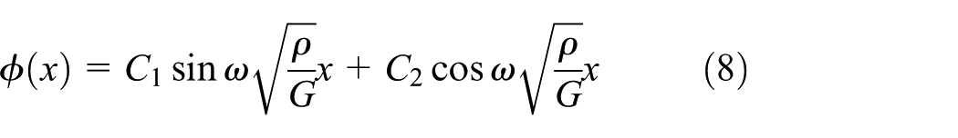
where
Drill string dynamics under torsional impacts
Impact torque
For HFTI drilling, HFTI (in the form of impact torque) act on a specific cross-section of the drill string. In this work, the impact load is assumed to be the pulses shown in Figure 4, where

The impact torque.
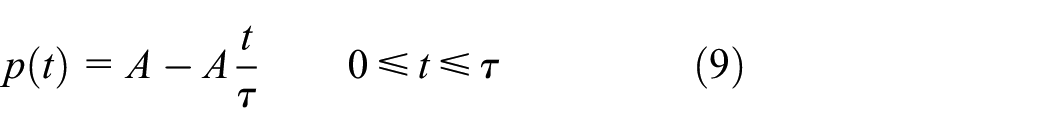
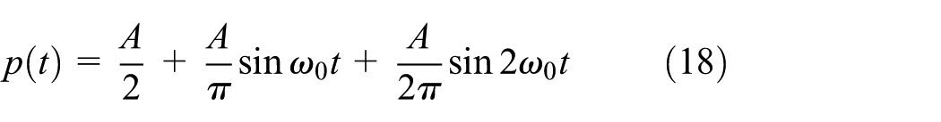
The impact load is piecewise, and thus, it is difficult to solve the equations with impact load. Therefore, a Fourier series is used to solve this problem. A function

where
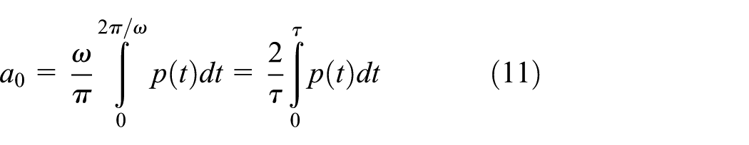


Substituting equation (9) into equations (11) to (13), the three equations are rewritten as
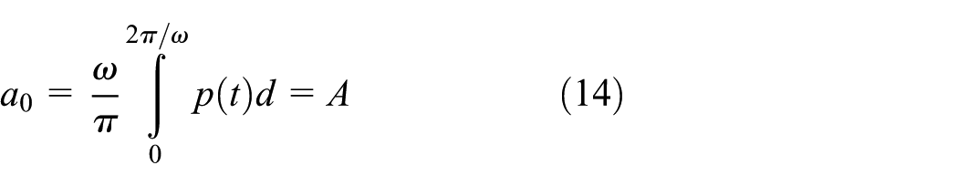


As a result, the expression of

where
Natural frequency and mode shape
For a drill string in a stick state, a fixed boundary condition at the drill bit

For the fixed end, the boundary condition is given as

Combined with equation (4), equations (19) and (20) are rewritten as


Substituting equation (8) into equations (21) and (22), the following two equations are derived

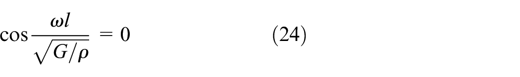
Based on equation (24), the natural frequencies of the drill string are obtained

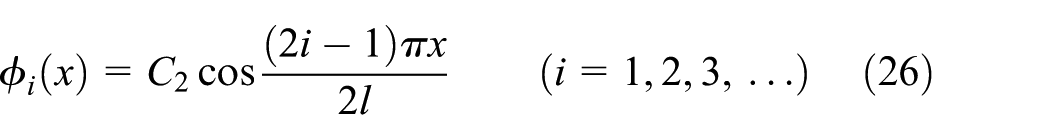
Combining equation (25) with equation (8), the mode shapes of the drill string are
For a drill string with a length of 3000 m, the first three mode shapes are shown in Figure 5.

The first three mode shapes of the drill string: (a) the first order, (b) the second order, and (c) the third order.
For the purpose of conducting quantitative analysis, a 3000-m drill string (the physical parameters are shown in Table 1) is analyzed.
Physical parameters of the drill string.

The first three natural frequencies are

Modal moment of inertia and modal load
Modal moment of inertia
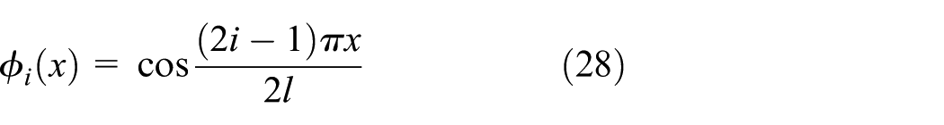
After obtaining the mode shape of the drill string, a normalized modal function is obtained by letting
Defining the modal moment of inertia of the ith order mode shape as

where J is the moment of inertia of a unit length drill string.
Combining equation (28) with equation (29), the modal moment of inertia of the drill string is rewritten as

The moment of inertia of the system presented in Table 1 is

Modal load
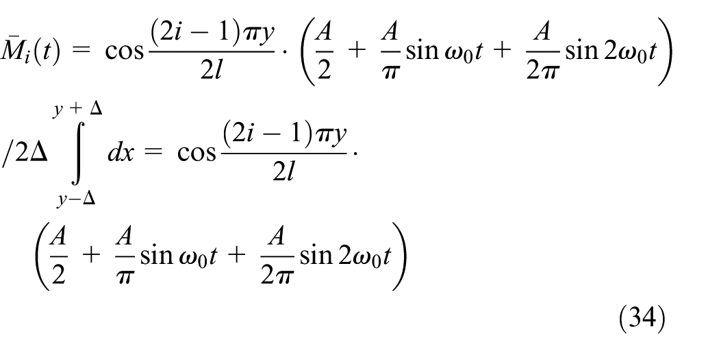
The ith modal load
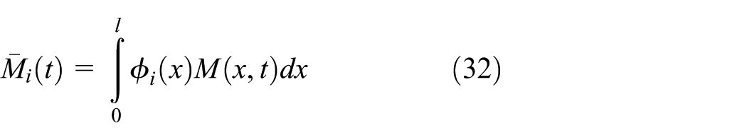
The HFTI are applied at a specific position on the drill string. In this study, the coordinate value of this position is regarded as y in the x axis. The high-frequency impact torque is a type of concentrated load. To simplify the calculation, this concentrated load can be regarded as a distributed load that acts on a micro-segment

For the distributed load in the micro-segment, y can be regarded as a constant. Thus, the modal load becomes
Principal coordinate of the system
Once the natural frequency and mode shape of the system are known, the continuous drill string can be analyzed using the approach utilized in a discrete system. In this work, the mode superposition method is used. For a continuous system, in theory, there are infinitely many mode shapes that should be superposed. In practical engineering, however, only the mode shapes that provide the main contributions are included. Therefore, in order to use the mode superposition method for the drill string, the continuous system is transformed into a discrete system. To obtain the dynamics of the drill string, equation (4) is rewritten as

where

In addition, the

The ith mode shape

where
The mode shape of the system can be obtained by analyzing the natural vibration characteristics of the system. However, the principal coordinate,
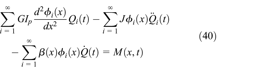
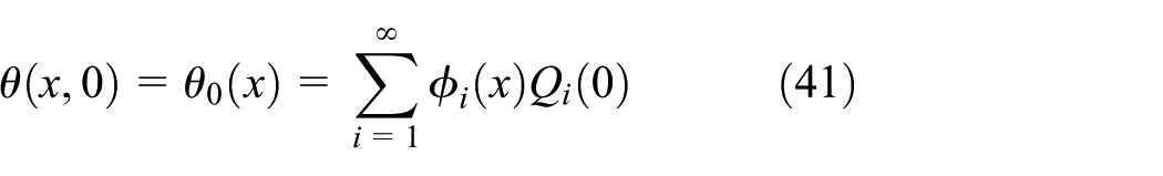
The initial conditions for equation (40) are

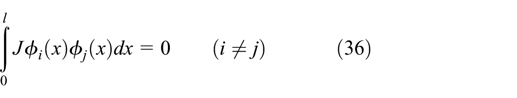
Multiplying

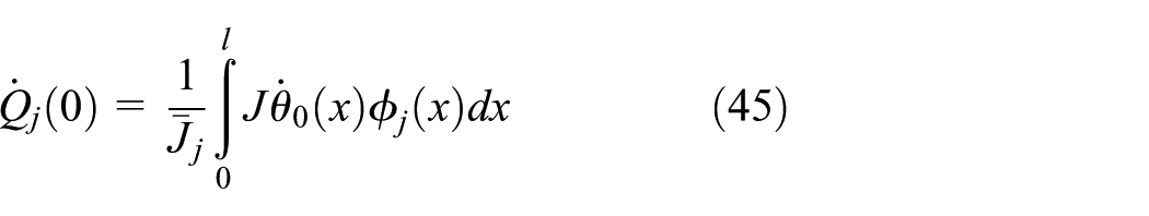
Performing a similar calculation, equations (41) and (42) are rewritten as

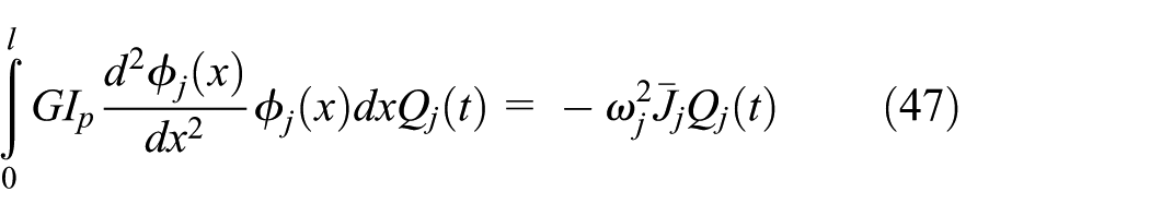
During the derivation process of stiffness orthogonality, there is

Combining with equations (29) and (32), the first term of equation (43) is given by
Thus, equation (43) becomes
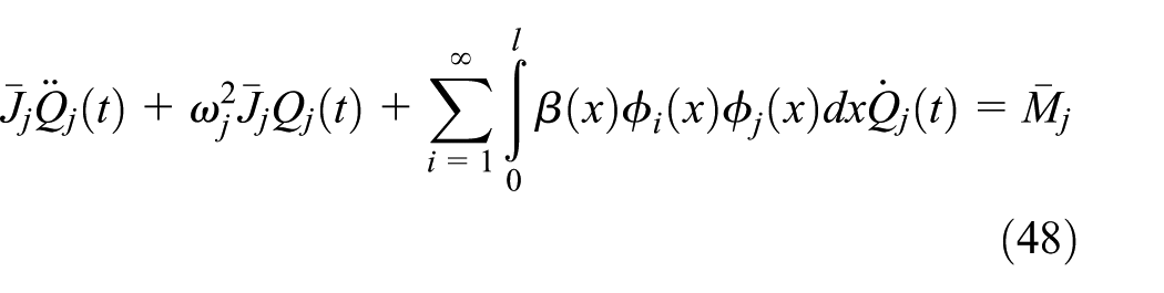
For equation (48), it is difficult to obtain a solution because of the non-symmetric matrix introduced by the third term. In order to decouple the principal coordinates of equation (48), the viscous damping coefficient is assumed to be 26

defining the damping ratio as

where a is a constant and
Combining equations (48) to (50), the differential equation of the principal coordinate that has been decoupled is given as
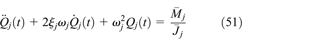
Using the transformation presented above, the problem of obtaining the system response becomes one of solving the modal response of a system with many independent degrees of freedom (DOF). The equation of each DOF contains a principal coordinate, and the solution is similar to that of the single-DOF system. The initial conditions of equation (51) are expressed by equations (41) and (42). After obtaining each principal coordinate, the dynamic response of the drill string can be obtained in terms of equation (35).
Equation (51) is an inhomogeneous equation, whose solution includes a solution of the associated homogeneous equation and a particular one. The associated homogeneous equation of equation (51) is given by

Combining this with the solution of the single-DOF viscously damped free vibration and the initial conditions given by equations (41) and (42), the general solution is given by

where


With both the initial displacement and initial velocity of the bit equal to 0, the general solution of equation (52) is 0. The particular solution of equation (51) depends on the type of loading. When there is no impact load acting on the drill bit, the solution of equation (51) is given by

where
For the constant term of the impact load (referred to as the first term of equation (18)), the corresponding modal impact torque is

where y is the location of the impact load on the drill string. This expression demonstrates that the principal coordinate is inversely proportional to the jth natural frequency
For the harmonic term of natural frequency equal to

where


For the harmonic term of natural frequency equal to

where


For the drill string under the driving torque (from the rotary table) and the impact torque, the solution of the principal coordinate (referred to as equation (51)) can be obtained using the mode superposition method

Case studies and discussion
In order to understand the response of the drill string, case studies were performed.
Case 1
In this analysis, the rotary table rotated at a velocity of 100 r/min, the impact frequency was 600 times per minute (10 Hz), and the torque impacts were located 1 m above the drill bit. For the impact generator, output impact torque was 366 N m, when the impact frequency was 10 Hz. 22
When using the mode superposition method to analyze drill string dynamics, only the first three modes were considered. In order to obtain the principal coordinate, system parameters were calculated. For a 3000-m drill string (some of the parameters are listed in Table 1), the system parameters were as follows:
Utilizing the parameters given above, the first three orders of the principal coordinate are


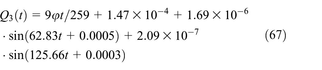
Substituting equations (65) to (67) into equation (35), the angular displacement of a point on the drill string is obtained by using the mode superposition method. The dynamic response of the drill string is given by

In equation (68),
Figure 6 shows the angular displacement of the drill string during the stick state, for the case where no torsional impacts act on the drill string. Figure 7 shows the angular displacement of the drill string during the stick state, for the case where torsional impacts (the impact frequency is 600 times per minute) are applied to the drill string. For the two cases, it was assumed that there was no relative angular displacement between the drill bit and the rotary table at t = 0. As can be seen from the two figures, the dynamic responses of the drill string is almost the same, which means the HFTI have little effect on drill string vibration. An explanation for this phenomena may be that the impact loads act at a place near the stick drill bit, and the impact frequency is higher than the natural frequency (in particular much higher than the first natural frequency) of the drill string.

Angular displacement of the drill string during the stick state for the case where no torsional impacts act on the drill string (assuming that at t = 0, there is no relative angular displacement between the drill bit and the rotary table).

Angular displacement of the drill string during the stick state for the case where torsional impacts (the impact frequency is 600 times per minute) act on the drill string (assuming that at t = 0, there is no relative angular displacement between the drill bit and the rotary table).
Case 2
For Case 2, an impact frequency of 300 times per minute was studied. For the impact generator, the output impact torque was 71 N m when the impact frequency was 5 Hz.
25
In terms of the analysis presented in the “Drill string dynamics under torsional impacts” section, the first three orders of principal coordinate can be described by equations (69) to (71). For the two cases, the difference appears primarily in the last terms, which have little influence on the equation. Since the structure and boundary condition of the drill string did not vary, the values of


Case 3
For Case 3, the rotary table velocity was set at 80 r/min (common in drilling applications), which is lower than the value for Case 1. All other system parameters were the same as those given in Case 1. According to the theoretical analysis in the “Drill string dynamics under torsional impacts” section, the equation of motion of the drill string can be described by equations (65) to (67). The rotary table velocity varied (in this case

Angular displacement of the drill string during the stick state in the case where the rotary table rotates at 80 r/min and torsional impacts (the impact frequency is 600 times per minute) act on the drill string.
Case 4
In Case 4, a drill string with a length of 4000 m was selected, and other size parameters of the drill string were similar to those presented in Table 1. For this case, the system parameters were as follows:


Similar to the above three cases, the drill string dynamics with and without impact are almost the same, which indicates that the effect of torsional impact on drill string dynamics is very small and can be neglected. For this case, only one figure is needed to show the drill string dynamics (Figure 9).

Angular displacement of the drill string during the stick state in the case where the drill string length is 4000 m and torsional impacts (the impact frequency is 600 times per minute) act on the drill string.
Conclusion
The problem of stick–slip vibration, which is detrimental to drilling equipment and drilling efficiency, was studied. In recent years, torsional impact drilling has been widely used to improve drilling efficiency. However, the influence of HFTI on drill string vibration was unknown. In this work, the effects of HFTI on drill string vibration in a stick state were analyzed. First, a mechanical model of a continuous drill string was established, with HFTI included and regarded as the external load. Next, a Fourier series was used to describe the impact loads, and the equations of motion were resolved using the mode superposition method. The dynamic response of the drill string was a combination of the mode shape and the principal coordinate. The first three orders of the Fourier expression were used to represent the impact load, and the summation of the first three orders of drill string response (related to each order of mode shape and principal coordinate) were applied, to characterize the drill string dynamics. Finally, a series of case studies was performed, where the impact parameters were obtained from a published laboratory test. The case study results demonstrate that HFTI have little influence on the vibration of a drill string in a stick state. This work also shows that HFTI will not excite or aggravate drill string vibration.
Footnotes
Handling Editor: Ali Kazemy
Declaration of conflicting interests
The author(s) declared no potential conflicts of interest with respect to the research, authorship, and/or publication of this article.
Funding
The author(s) disclosed receipt of the following financial support for the research, authorship, and/or publication of this article: This research is supported by the China Postdoctoral Science Foundation (No. 43XB3793XB), National Key Research and Development Program (No. 2018YFC031 0204), Key Research Project of Sichuan Province (No. 2017GZ0365), National Natural Science Foundation of China (No. 51674214), and Open Research Subject of MOE Key Laboratory of Fluid and Dynamic Machinery (No. szjj 2016-062).