
Abstract
This article discusses an increase in dynamic force range in a spring–damper unit achieved by elimination of sealings’ friction. This friction is a part of damping force that cannot be controlled; therefore, it is undesirable in magnetorheological dampers. A new design of a magnetorheological damper with no friction force is described and compared with a traditional magnetorheological damper consisting of a piston and piston rod seals. In the traditional design, fluid is forced to flow by a hydraulic cylinder with high friction caused by sealings. In order to eliminate this friction, a frictionless unit made of metal bellows was designed. Elastic metal bellows can be sealed only by static seals. The measurement of force–velocity dependency was carried out for the original and the new damper with the same magnetorheological valve. The results indicate that the frictionless unit exhibits a significant improvement in the dynamic force range. In the case of adaptive-passive damping control, the increase in the dynamic force range enables the improvement of vibration elimination in the entire frequency range.
Introduction
Vibrations – an accompanying feature of movement – are generally undesirable. There are several ways of how to reduce them. The commonly used passive dampers do not need any power supply; however, they are not very efficient, as it is not possible to achieve good damping in a wide frequency range with a single damper. Another way of how to eliminate vibrations is using an active element – actuator. This suspension is better in vibration elimination especially at low frequencies, but it is energy consuming. Therefore, active suspension systems are used specifically for light sprung masses. 1 Semi-active damping is often referred to as an advantageous combination of passive and active vibration elimination. 2 However, the method of semi-active damping is more similar to that of passive damping because both methods are based on the reduction of vibration energy within the system, 3 while the active control adds the energy to the system. Semi-active damping differs from the passive one in controllability of dissipated energy in the damper. Magnetorheological (MR) damper is one of the examples of such devices. Usually, it consists of a piston with the coil that can generate the magnetic field in the active zone.4,5 However, there are several designs of MR dampers consisting of the piston unit and the external MR valve.6,7 This type of damper has to be filled with an MR fluid – a smart material consisting of micro- or nano-sized ferromagnetic particles, a carrier fluid and some additive ingredients. 8 When this fluid is exposed to the magnetic field, its yield stress dramatically raises, which increases damping forces.9,10
Figure 1(a) shows the example of a suspension system with a vibrating base and sprung mass. One of the main aims of this suspension system is to minimize the vibrations transferred from the base to the sprung mass, that is, to keep the transfer ratio

where

Therefore, it is reasonable to adapt the damping for current frequency of excitation. The adaptive-passive damping control is one of the suitable methods for elimination of vibrations with harmonic excitation. 12 It is based on variable damping in time, high damping in the vicinity of resonance (equation (1)) and low damping for isolation area (equation (2)). 13 Yang et al. 5 proved that the semi-active suspension with an MR damper with a high dynamic force range and a short response time is very efficient in vibration elimination. The response time is an interval necessary to change the damping ratio. 14 The time period of this change depends on the fluid response time, coil inductance and eddy currents in the magnetic circuit. 15 Currently, the world’s fastest MR damper with response time less than 2 ms was developed by Strecker et al. 16
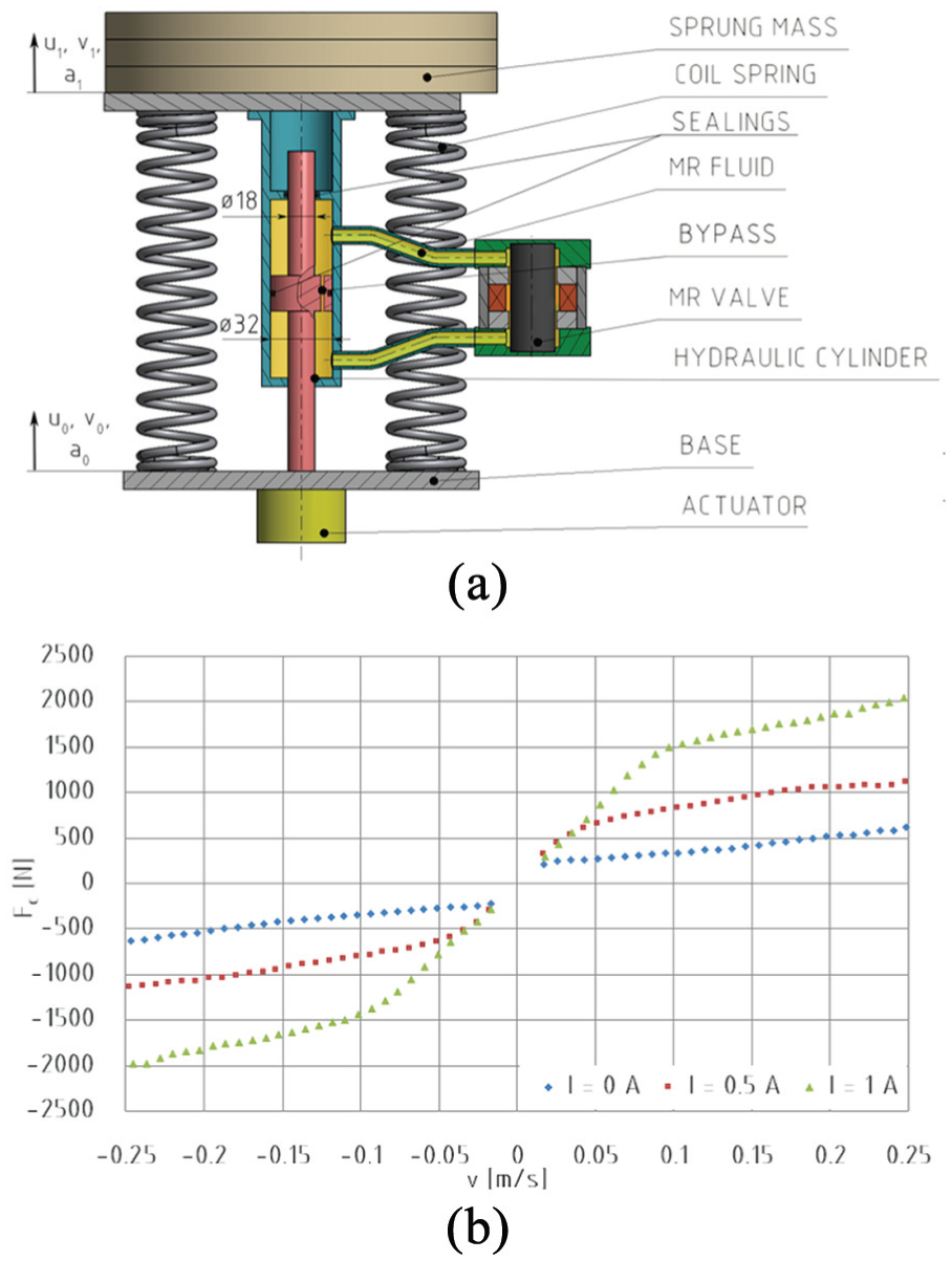
(a) Scheme of the suspension system and (b) force–velocity dependency of the MR damper with piston.
Dynamic force range of an MR damper
Generally, the greater the possibility of intervention in the system, the more effective regulation can be achieved.
17
The dynamic force range of an MR damper (equation (3)) depends on the damper piston velocity, which can be calculated as the ratio of the damping force in the activated state

Several methods of dynamic force range increase have been described. Yang et al. 5 optimized the geometry of gap and piston. Cvek et al. 19 chose the fluid that exhibits the greatest differences between the yield stress in the ON and OFF states. The influence of sealing friction has not yet been directly described in the available literature. However, it can be observed from Table 1 that the friction force could be a significant part of the damping force in the inactivated state, especially for the dampers with a low damping force.
Forces and dynamic force ranges of the chosen MR dampers.

MR: magnetorheological.
The original MR damper with a piston
Two dampers with the same external MR valve are discussed in this study. The MR valve design is mentioned in our previous study,
21
which deals among other things with F–v dependency prediction by an analytical model and its verification. In the first version of the MR damper, the fluid was forced to flow through the MR valve by a commercially available hydraulic cylinder. Seals are placed between the cylinder and the piston or the piston rod. These seals are the most significant cause of friction force that decreases a dynamic force range of an MR damper. The sprung mass was connected with the base by the coil spring and the damper; see Figure 1(a). This configuration is called a rigidly connected damper
22
and the absolute transmissibility of the system with a constant damping ratio

However, the damping force
Problem formulation
The efficiency of semi-active or adaptive-passive suspension depends on the dynamic force range of the MR damper (equation (3)). Due to the Coulomb friction, the dynamic force range of the MR damper with a piston is insufficient, especially for small piston velocities, which is confirmed by very small differences in the transfer ratios for different currents in the coil of the MR damper with a piston, particularly for frequencies higher than

Transfer ratio of suspension with the MR damper with a piston.
The adaptive-passive damping control will be used in this study. It is necessary to minimize the forces in the OFF state to achieve a lower transfer ratio of the suspension system in the isolation area. The friction is a component of the OFF state force that can be changed without significantly affecting the ON state in an undesirable way. The friction in the traditional damper is caused especially by the sealing of surfaces with the motion relative to each other. The friction force depends on the pressure of the fluid inside the damper. The higher the pressure, the higher the downforce on the sealing, thus the higher the friction force. 23 However, commonly the friction force is considered to be constant for various velocities of the piston. 4 Heipl and Murrenhoff 24 reduced this resistance using proper seals; however, the friction force was still significant. The friction can be completely eliminated using the bellows with static seals.25,26 Elastic metal bellows change the connection of the damper from rigidly to elastically connected; this change should reduce a transfer of vibrations at high frequencies. 27 This hypothesis needs to be verified for the suspension parameters mentioned in this study.
Material and methods
The new MR damper with bellows
Friction is eliminated by the absence of piston and piston rod and thus its sealing as well; see Figure 3. Sealing is achieved using elastic metal bellows which are sealed with static seals.

The suspension system with the MR damper with bellows.
The structural modification regarding the absence of piston and piston rod cause a change in the dynamic behaviour of the system in comparison with the system with the original damper because a new damper has to be considered elastically connected. In this case, the transmissibility of the system is

where
Lids of the new damper (pos. 1) in Figure 4 are connected by a frame (pos. 2). Considering that the central part (pos. 3) is fixed, a downward movement of the frame causes compression of the upper bellows, while the lower bellows (pos. 4) is expanded. The length change of bellows caused the MR fluid flow via two channels. The first one is through the hole marked

A detailed scheme of the bellows unit.
The bellows unit can be screwed to the weights and the actuator via threaded holes in the frame (pos. 8) and in the lid (pos 1). This connecting hole in the lid can also be used for filling the fluid. It is sealed with the screw (pos. 9) and the O ring (pos. 10), and it is tightened to a conical countersink. This is an unconventional method of sealing; therefore, a leakage test was performed prior to manufacturing of the lids.
Measurement setup of force–velocity dependency
The MR damper with bellows shown in Figure 5(a) was mounted into the test rig as illustrated in Figure 5(b). The system parameters as sprung mass

The bellows unit (a) in the test rig (b).
The damping force was measured with a strain gauge load cell INTERFACE 1730ACK-50 kN mounted between the sprung mass and the frame. The stroke of movement
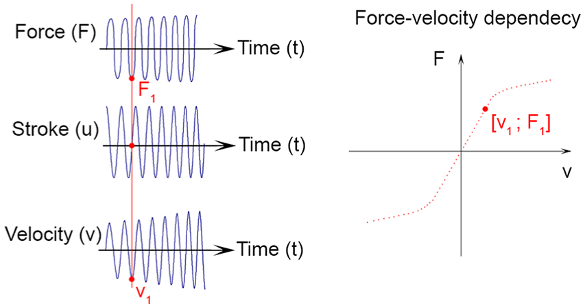
Scheme of force–velocity dependency measurement.
Measurement setup of the transfer ratios
The setup of this type of measurement was the same as that for the force–velocity measurement, only the load cell was removed and the actuator acceleration

Kinematic excitation was realized by linear sweep sine for frequencies from


Results and discussion
Force–velocity dependency of the MR damper with bellows
Force–velocity dependency of the MR damper with bellows in Figure 7 differs from the MR damper with a piston in Figure 1(b), especially for the current of 0 A due to the friction elimination.

Force–velocity dependency of the MR damper with bellows.
However, friction also affects the states with non-zero currents in the coil; therefore, the damping forces of the MR damper with bellows are lower than the forces of the MR damper with a piston. The slope of the measured curves is slightly different for both dampers; this is caused by different piston areas. Traditionally, it is given by a diameter of piston
Force–velocity dependencies of both dampers differ also by the hysteresis because of the different stiffness of the damper connection

Comparison of force–velocity dependencies of both MR dampers with hysteresis caused by the springs.
Transfer ratios of the MR damper with bellows
A resonance of the suspension system with the MR damper with bellows and no current in the coils of the MR valve is around 9 Hz, see Figure 9. A rise of the current significantly reduces the transfer ratio
Transfer ratio of suspension with the MR damper with bellows.
There are few small peaks in the transfer ratios between
Benefits of the new MR damper with bellows
Both the above-mentioned dampers were compared in terms of the dynamic range and the transfer ratio of suspension systems with these dampers. The dynamic range

Comparison of the dynamic range.
It is obvious that the MR damper with the bellows unit has a higher dynamic range for the entire velocity range in comparison with the MR damper with piston. The increase of the dynamic range is more than 100% for the velocity lower than
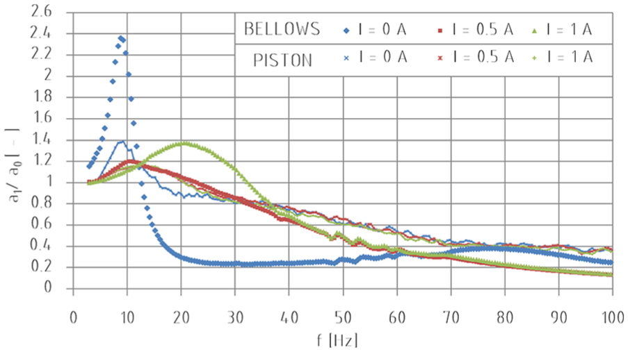
Comparison of the transfer ratios of adaptive-passive controlled MR dampers is shown in Figure 11(a). The results show that the MR damper with bellows exhibits a lower transfer ratio in the whole frequency range than the transfer ratio of the MR damper with a piston. A new design of the damper with bellows affects the connection of the damper.

Comparison of transfer ratios: (a) adaptive-passive I = 1 A (f ≤ 12 Hz) and I = 0 A (f > 12 Hz); (b) passive I = 0.5 A.
The MR damper with a piston can be considered as rigidly connected, while the MR damper with bellows is elastically connected
22
because the bellows change their volume as a function of fluid pressure inside them. Davis et al.
27
call this resistance of bellows against the volume changes called as volumetric stiffness, which is a key parameter of the stiffness of frictionless damper connection
The improvement of the transfer ratio in the isolation area caused by an elastically connected damper occurs in the case of high velocity and small stroke of the damper when the damping force
Benefits of the elastically connected dampers are well known and often used, for example, in automotive dampers which have elastic parts (silent blocks) in eye mounts because of vibration elimination at high frequencies and low strokes. The MR damper with bellows works similarly; however, the elasticity is given especially by volumetric stiffness of the bellows, more precisely by its projection into axial direction–pressure thrust stiffness. The selection of suitable bellows is very important for the MR damper design because it affects the ratio
Conclusion
The frictionless MR damper with bellows has been tested in this study and compared with the original MR damper with a piston. The bellows unit was designed to eliminate friction by replacement of the piston and piston rod sealings by static seals of bellows. The measurement of force–velocity dependency proved that the force caused by friction in the damper has a significant impact on the dynamic force range of such device. An increase of the dynamic force range for the frictionless damper is more than 100% for damper velocity lower than
The adaptive-passive damping control was used to compare the behaviour of the frictionless MR damper and the original MR damper with a piston in the same suspension. The transfer ratio of the suspension with a frictionless MR damper was lower in the whole frequency range in comparison with the transfer ratio of the suspension with the original MR damper with a piston. A new design of the damper with bellows can be considered as elastically connected. This results in a lower transfer ratio for high frequencies in comparison with the transfer ratio of the damper with a piston which is considered as rigidly connected.
The dynamic force range together with the response time of the MR damper is the most important parameter limiting the performance of suspension systems controlled by semi-active algorithms. It can be concluded that the use of the bellows unit instead of the piston unit brings about a promising improvement of suspension quality in semi-active suspension systems.
Footnotes
Handling Editor: ZW Zhong
Declaration of conflicting interests
The author(s) declared no potential conflicts of interest with respect to the research, authorship and/or publication of this article.
Funding
The author(s) disclosed receipt of the following financial support for the research, authorship and/or publication of this article: This study was supported by the kind sponsorship of various grants and numerous agencies. This study was especially supported through GAČR 17-10660J, GAČR 17-26162S and FSI-S-17-4428.