
Abstract
In the traditional manufacture methods of metal bellows, such as tube bulging and hydroforming, the dies and tools are generally used. In these methods, it is very inconvenient to change the shapes of bellows because the dies and tools should be changed, which often result in extremely high cost. In this study, a novel manufacture method without any dies and tools for producing the metal bellows with various shapes was proposed. This novel method is called as dieless bellows forming process with local heating technique. The factors which affect the shape of metal bellows and the deformation behavior of metal tubes during the dieless metal bellows forming process were investigated by experiment and finite element method simulation in this study. The metal tubes (SUS304, JIS) with the dimensions of 13.8 (D)×2 (t) mm and 25 (D)×2 (t) mm were used to study the availability of the newly proposed method for manufacturing the metal bellows with different tubular materials. As a result, the metal bellows with good shapes were successfully obtained using the newly proposed method. The results also showed that the shape of the metal bellows can be easily changed by adjusting the compression ratio. It was clarified that the deformation parameters, such as compression ratio and heating length, have the significant effects on the convolution height, pitch and deformation behavior of metal tube during dieless metal bellows forming process. The suitable parameters should be chosen to manufacture the metal bellows with the expected shape.
Keywords
Introduction
Metal bellows have wide applications in piping systems, automotive industries, aerospace, automatic control and measuring instruments, transportation, nuclear energy industry and microelectro mechanical systems. Metal bellows have the airtight and elastic properties because they are one kind of special pipe, and the shape of convolution of the metal bellows can be easily changed by the external force along the axial direction of metal bellows. The expansion and shrinkage caused by heating and cooling, as well as mechanical vibrations of structures, can be absorbed by the metal bellows because of their special properties. 1 The rapid growth of modern industry is prompting the increasing requirement of metal bellows with various shapes. For example, in the recent years, with the development of the micro machines and the new techniques in the medical treatment, the metal bellows with various shapes for producing the special sensors and mechanical equipment show an increasing demand. 2 To produce these special parts, the metal bellows with various shapes are desired. For the conventional manufacturing methods for metal bellows, such as press working and laser welding process, 3 roll type incremental forming, 4 tube hydroforming, 5 combination process of bulging and upsetting 6 and gas bulging at elevated temperature, 7 the dies and tools are generally required. In these methods, it is very inconvenient to change the shapes of metal bellows because the dies and tools should be changed, which often result in extremely high cost. In addition, for some metal bellows with complicated shapes, such as the different pitches, convolution heights along the axial direction of metal bellows, the special dies or tools with complicated shapes are required. The manufacture of the special dies and tools will be bound to result in the high cost for these conventional methods. In such cases, Furushima et al. 8,9 proposed a semi-dieless metal bellows forming process to produce the metal bellows with various shapes. In the semi-dieless metal bellows forming process, the mandrel was used to keep the stability of forming process. However, it is very difficult to push the mandrel out of the bellows after the forming process. Sometimes, the shape of bellows was changed after the mandrel was pushed out with a tensile test machine. In addition, it takes more time and cost to manufacture metal bellows. Therefore, in order to manufacture the metal bellows with various shapes with low cost, the dieless metal bellows forming process with local heating technique was newly proposed in this study.
For this novel metal bellows manufacture method, the dies and tools are not required. The shapes of metal bellows can be changed only by adjusting the compression ratio. The factors which affect the shape of metal bellows and the deformation behavior of metal tubes during the dieless metal bellows forming process were investigated by experiment and finite element method (FEM) simulation in this study. As a result, the metal bellows with good shapes were successfully obtained using the newly proposed method.
Metal tubes and experimental method
In this study, the continuous buckling phenomenon, which appears in the metal tubes at the action of compression force in the axial direction, was used to produce the metal bellows. To control the location of the buckling, the local heating technique and water cooling method were utilized. Figure 1 shows the principle of dieless metal bellows forming process. At the first stage, the metal deformation part was heated to a given temperature by a heating device. Two nozzles were employed to supply the cooling water to control the heat diffusion along the axial direction of the metal tube. When the temperature reached up to the predetermined value, the metal tube started to move with two different speeds V 1 and V 2 (V 1 > V 2) of tube ends. In the second stage, the heated parts started to deform and became thicker due to the compression force caused by the speed difference of tube ends. With the continuous action of compression, the first convolution was formed, as shown in Figure 1(c). When the first convolution moved to the cooling part, it was cooled to a relatively low temperature and became hard enough to prevent further deformation. Its shape was fixed. At the same time, the second convolution was formed, as shown in Figure 1(d). The metal bellows were formed with the forming process continuing. The metal tubes (SUS304, JIS) with the dimensions of 13.8 (D) × 2 mm (t) and 25 (D) × 2 mm (t) were used to study the availability of the newly proposed method for manufacturing the metal bellows with different tubular materials.
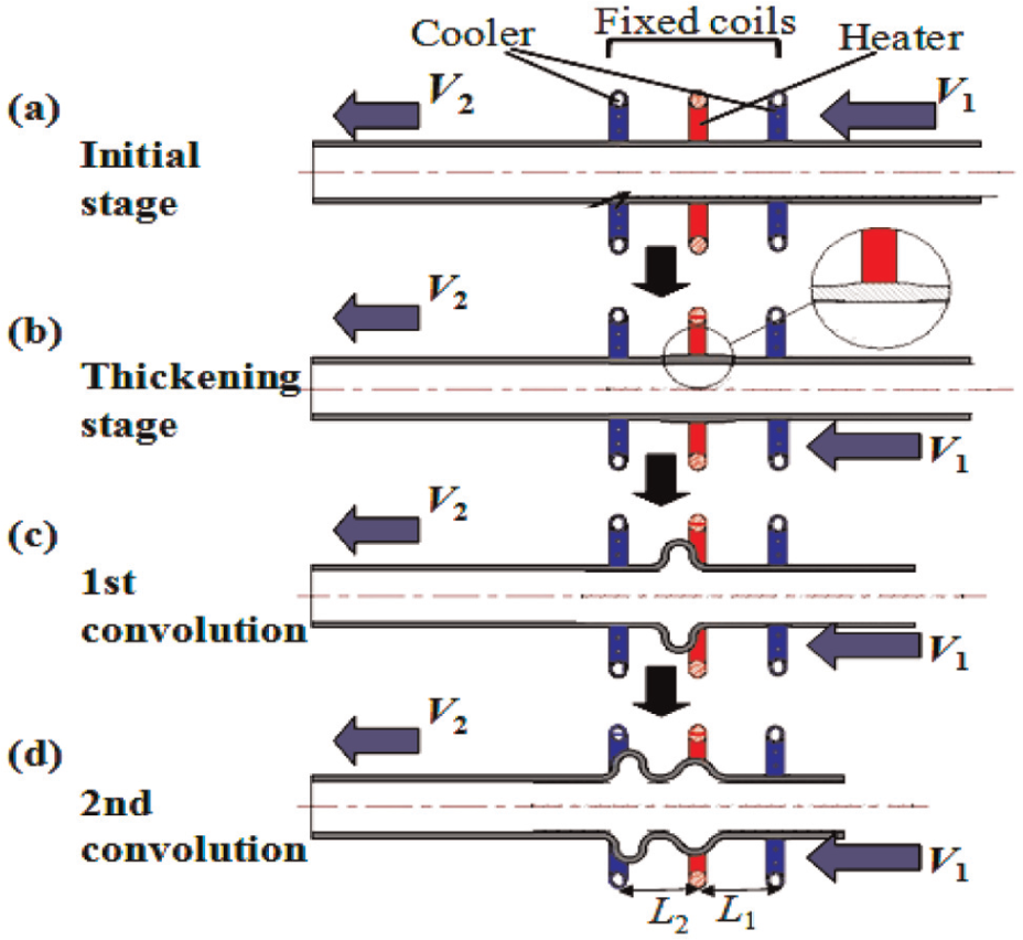
Schematic illustration of the principle of semi-dieless metal bellows forming process: (a) initial stage, (b) thickening stage, (c) first convolution and (d) second convolution.
According to the principle of the dieless forming process, the experimental apparatus were developed. 9 The schematic illustration of the device is shown in Figure 2. The two servomotors were employed to drive the two actuators to provide the moving speeds (V 1 and V 2) of drive plates 1 and 2, respectively. The tube ends were fixed at both drive plates by the chucks. By adjusting the separated servomotor rotational speed, the moving speed V 1 and V 2 can be changed separately. The local heating was realized by an induction heating coil. The heating power was supplied by a high-frequency induction heating device with a maximum output power of 10 kW and a frequency range of 150–400 kHz (type: EASYHEAT LI 8310). The ultra-compact digital radiation temperature sensor (type: KEYENCE FT-H40K) was used to measure the surface temperature of heating zone of the metal tube during the dieless metal bellows forming process. In this study, the temperature of heating zone was set in a range of 1150 °C–1200 °C. To obtain the temperature distribution of the heating zone, a thermocouple was welded on the surface of the metal tube. In the forming process, the thermocouple was made to move with the tube and the instantaneous temperature of the weld point was measured. The data were collected by a datalogger (type: MEMORY HiLOGGER LR8431). The coolers in Figure 2 are the water-cooled nozzles. The compression force was measured by a load cell (type: KISTLER MODELS 9130B), which was fixed between chuck and drive plate 1. A computer was used to record the data of compression force in the forming process.
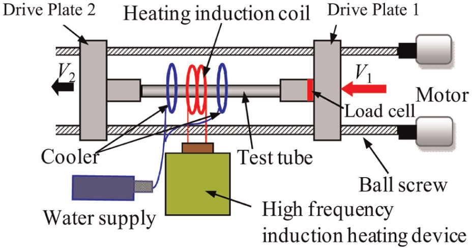
Schematic illustration of an experimental apparatus for dieless metal bellows forming process. 9
FEM simulation of dieless metal bellows forming process
FEM simulation model
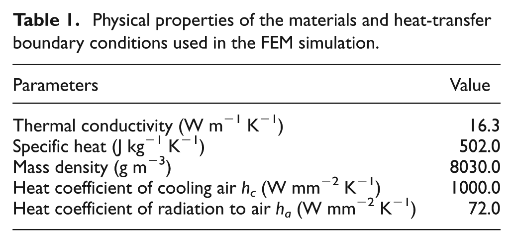
To investigate the deformation behavior of metal tubes in the dieless metal bellows forming process with different technological parameters, the FEM simulation of the forming processes was carried out. The dynamic explicit method of LS-DYNA 971 was used. The eight-node solid half-model was employed. Figure 3 shows the FEM simulation model used in this study. The metal tube was assumed as a temperature-dependent elastic–plastic body. The heating and cooling coils and punches were assumed as rigid bodies. To simplify the FEM simulation, the high-frequency induction heating process was assumed as a heat-transfer process. The heating coil was assumed as a heating source with a constant temperature (e.g. 1200 °C). The metal tubes were heated by the thermal radiation from the heating coil. The same assumptions were applied for the cooling coils. The temperature of cooling coils was assumed as a constant value of 23 °C. The transfer of heat between the heated metal tube and cooling coils was simplified as through the thermal radiation. The metal tube (SUS304) with a diameter of 13.8 mm and a thickness of 2 mm was used in the simulation. The parameters of the metal tube physical properties and heat-transfer boundary conditions used in the FEM simulation are given in Table 1.
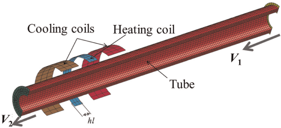
Half-model of FEM simulation for dieless metal bellows forming process.
Physical properties of the materials and heat-transfer boundary conditions used in the FEM simulation.
Verification of the FEM simulation model
To verify the availability of the FEM simulation model proposed in this study, the temperature distribution curve obtained in the experiment and FEM simulation was compared. The temperature distribution of the heating part was measured by a thermocouple. The temperature distribution curves of deformation part of the metal tube in the experiment and FEM simulation of the dieless metal bellows forming process are shown in Figure 4. It can be seen that the temperature distribution curve in the FEM simulation has a good agreement with the one in the experiment, although there is a little difference in the low temperature part of the metal tube. This little difference is due to the fluctuations in the cooling water flow in the experiment. From the comparison between the temperature distribution curves in the experiment and FEM, it can be seen that the assumption for the heating and cooling process is available. Furthermore, the simulation results obtained with this model is reliable.
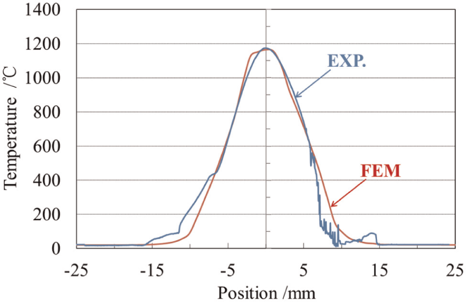
The temperature distribution of heating part of metal tube in experiment (EXP.) and FEM simulation.
Results and discussion
Shape of metal bellows manufactured with dieless metal bellows forming process
Figure 5(a) shows the metal bellows manufactured with the dieless metal bellows forming process. It can be seen that the metal bellows with uniform shape were successfully obtained with a compression ratio of 1.7. The diameter and the pitch of the metal bellows are about 32 and 12 mm, respectively.
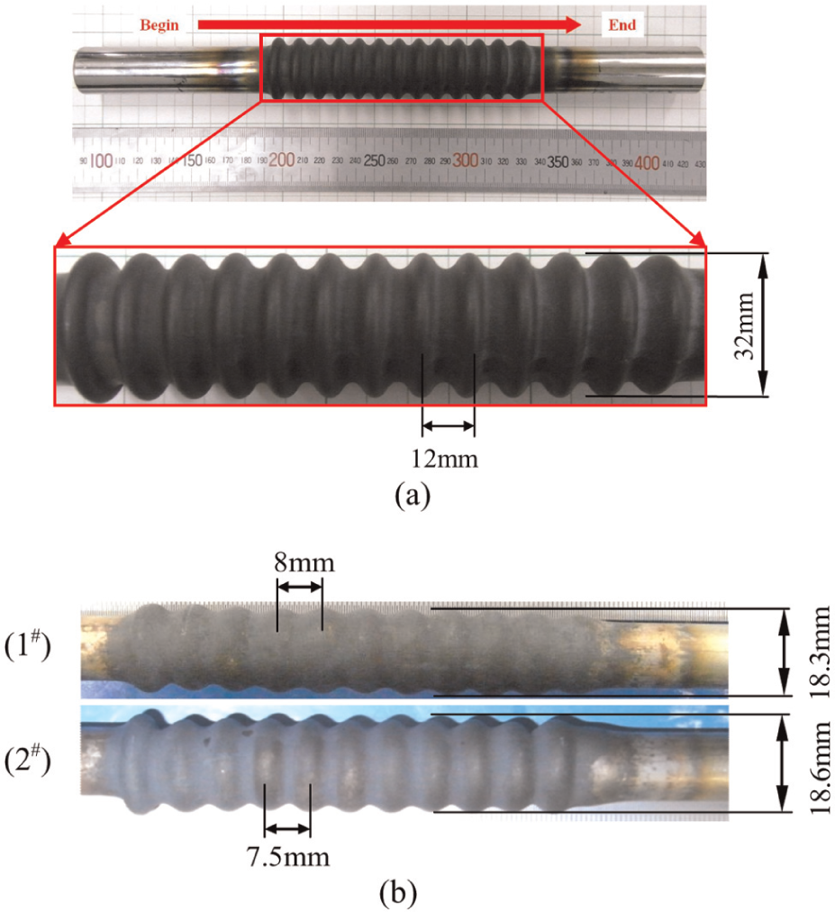
Metal bellows manufactured with dieless metal bellows forming process—(a) initial dimension of metal tubes, D × t: 25 × 2 mm; compression ratio, V 1 /V 2 = 1.7 and (b) initial dimension of metal tubes, D × t: 13.8 × 2 mm; compression ratio, (1#) V 1/V 2 = 1.7 and (2#) V 1/V 2 =1.8.
Figure 5(b) shows the metal bellows manufactured with dieless metal bellows forming process using a SUS304 tube with an initial dimension of 13.8 mm (D) × 2 mm (t). The metal bellows with a diameter of 18.3 mm and a pitch of 8 mm were obtained with a compression ratio of 1.7. Furthermore, the metal bellows with a diameter of 18.6 mm and a pitch of 7.5 mm were also successfully obtained with a compression ratio of 1.8. By comparing the two metal bellows manufactured with different compression ratios, it can be known that the diameter of metal bellows increased and the pitch decreased with the increase in the compression ratio. It means that the shape of the metal bellows can be changed by changing the compression ratio. Therefore, this novel manufacturing method for metal bellows is suitable to produce the metal bellows with various shapes.
Effect of compression ratio on compressive force and convolution height and pitch
The temperature distribution of the heating part of metal tube during the forming process is shown in Figure 4. The temperature shows a gradient distribution in both sides along the length of the metal tube during the forming process. The maximum value of the temperature was controlled at the range of 1150 °C–1200 °C. Figure 6(a) shows the varying of the compressive force during the forming process of one convolution. The compressive force varies sinusoidally in the forming process. The maximum value of compressive force appears in the thickening stage. It was examined by the unaided eye in the experiment. The effect of compression ratio on the maximum compressive force is shown in Figure 6(b). It can be seen that the maximum compressive force increased with the increase in compression ratio under the same temperature condition. With the increase in compression ratio, the deformation rate is increased. Thus, the maximum compressive force is also increased.
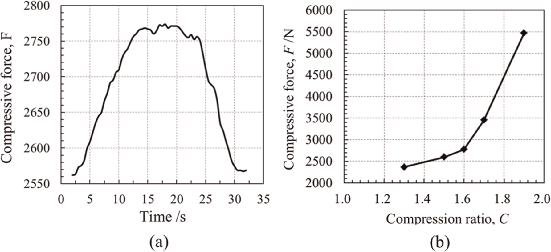
(a) Compressive force during the forming process of one convolution and (b) effect of compression ratio on compressive force.
Figure 7 shows the effect of compression ratio on the ratio of convolution height to initial diameter of the metal tube (h/D 0). The relationships between the compression ratio and the value of h/D 0, obtained by both experiment and FEM simulation, appeared the same trends. The value of h/D 0 increased with the increase in compression ratio. The increase in the value of h/D 0 became slow when the value of compression ratio was higher than 2. In the dieless metal bellows forming process, the convolution height becomes larger with the increase in the compression ratio. It can be predicted that when the convolutions contact each other, the convolution height will not increase anymore. Therefore, for the given metal tube, the maximum value of h/D 0 should be a constant value.
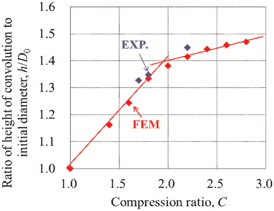
Effect of compression ratio on the ratio of convolution height to initial diameter of the metal tube.
Figure 8 shows the effect of compression ratio on the ratio of the pitch of convolution to the initial diameter of the metal tube (p/D 0). The value of p/D 0 decreased when the compression ratio increased from 0 to about 2.5. The value of p/D 0 became constant when the compression ratio was higher than 2.5. During the dieless metal bellows forming process, the pitch became smaller when the compression ratio increased because the distance between convolutions became near. When the convolutions contacted each other, the pitch had a constant value. Therefore, for the given metal tubes, the maximum pitch is also constant. Based on the physical properties of the metal tube, we can determine the maximum pitch as well as the maximum height of convolution in the dieless metal bellows forming process.
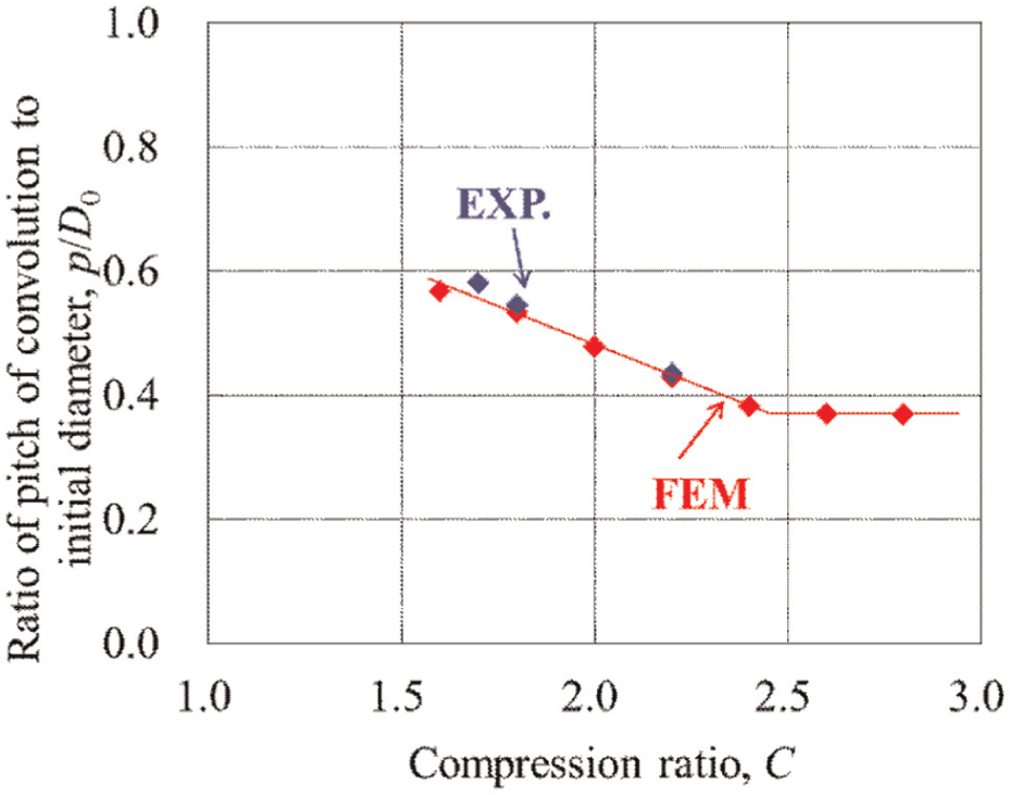
Effect of compression ratio on the ratio of pitch of convolution to the initial diameter of the metal tube.
Effect of heating length on the deformation behavior of metal tubes in dieless metal bellows forming process
To clarify the effect of heating length (HL) on the deformation behavior of metal tubes during the dieless metal bellows forming process, the FEM simulation of dieless metal bellows forming processes with different HLs of 4.8, 9.6, 14.5 and 29 mm was carried out. The temperature distributions of heating part obtained in the FEM simulation with different HLs are given in Figure 9. The deformation behaviors of metal tubes in the dieless metal bellows forming process with different HLs are shown in Figure 10. The deformation process can be kept stable when the HL is not so large, as shown in Figure 10(a) and (b). However, with the HL becoming longer, the deformation process became unstable (Figure 10(c)), even the convolution still can be formed. When the HL was 29 mm, the metal tube was bent and the convolution could not be formed, as shown in Figure 10(d). It can be seen that the HL is one key parameter which should be considered to manufacture the bellows using the dieless forming process. According to the large number of tests done by the authors, it was also found that when the HL was too short, the convolution height became lower and the pitch became larger with the same compression ratio in the dieless metal bellows forming process. Therefore, the suitable HL is required to obtain bellows with sound quality in the dieless bellow forming process.
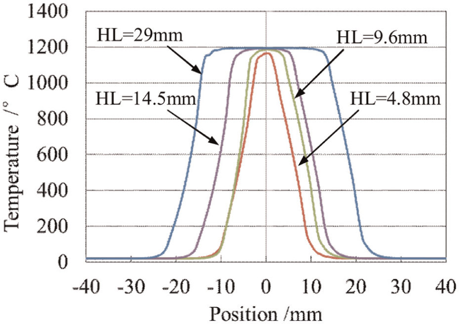
Temperature distribution of heating part with different HLs.
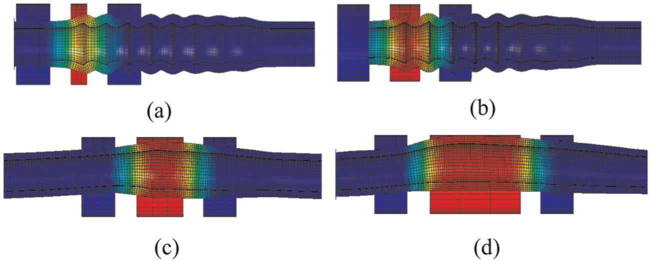
Deformation behavior of metal tube in dieless metal bellows forming process with different HLs (compression ratio, C = 2.0; temperature, 1200 °C): (a) HL = 4.8 mm, (b) HL = 9.6 mm, (c) HL = 14.5 mm and (d) HL = 29 mm.
Conclusion
To manufacture the metal bellows of various shapes from the metal tube with high ratio of thickness to diameter, the dieless metal bellows forming process was newly proposed in this study. The SUS304 steel tubes with the thickness of 2 mm and outside diameters of 13.8 and 25 mm were used to fabricate the metal bellows. To study the deformation behavior of metal tubes during the dieless metal bellows forming process, the FEM simulation was employed. The main findings are summarized as follows:
The novel dieless metal bellows forming process proposed in this study can be used to manufacture the metal bellows of various shapes from the metal tube with high ratio of thickness to diameter. The shapes of metal bellows can be easily changed by changing the compression ratio of forming process.
The compressive force varies sinusoidally in the forming process. The maximum compressive force increased with the increase in compression ratio under the same temperature condition.
The compression ratio and HL of the deformation part have the significant effects on the convolution height, pitch and deformation behavior of metal tube during the dieless metal bellows forming process. Therefore, the suitable compression ratio and HL are required to manufacture the bellows with expected shape and quality by dieless forming process.
Footnotes
Declaration of conflicting interests
The authors declare that there is no conflict of interest.
Funding
This work was supported by the Showarasenkan Seisakusyo Co., Ltd of Japan and the Scientific Research Starting Foundation for Introduced Talents of Northeastern University, P.R. China (Grant No. 02080021233061).