
Abstract
The missile launching system is a typical complex mechanical system, which is becoming increasingly larger in scale and more complicated in structure. Designing these types of products often requires repeated complex and time-consuming model design, calculation, and analysis of the dynamics of the system. The most time-consuming is repeatedly modifying the geometric and dynamics models. In this article, we put forward a new method for bidirectional-driving parameter between CAD and CAE, by changing the geometric model parameters, which directly changes the dynamics model. A parameterized multibody system dynamics modeling and analysis software for missile launching system are proposed, which gathered modeling, solving, visual simulation as a whole, and realized design parameters seamless transfer between geometric models and dynamics models for missile launching system. In order to examine the correctness of the simulation results, a parameterized experimental platform for missile launching system is designed, which can modify the key parameters as designed in simulation software. Finally, a missile launching system simulation and test examples are given, and the simulation analysis and experiment results demonstrate that the overall trend of the simulation results of multi-rigid and rigid-flexible coupling dynamics model is consistent with the experiment results.
Introduction
With the development of the national economy and defense technologies, the structures and scales of the mechanical system such as missiles, multiple launch rocket systems, tanks, and other weapon systems are becoming more and more complex. The missile launching system is a typical mechanical system that usually uses the method of finite element and multibody system (MS) dynamics for analyzing, which often needs repeat, complex, and time-consuming modeling; kinematics dynamics numerical calculation; and large amounts of data analysis. 1 The missile launching system can be regarded as the complex MS, which is composed of large-scale bodies and a variable types of joints. The MS dynamics is an important basis of design and experiment of dynamic performance of weapons, ships, aviation, aerospace, vehicle, and general mechanical products. The foundation of multi-rigid-body dynamics had been established by the efforts of many scholars, such as Wittenburg, 2 Schiehlen, 3 and Kane, 4 who developed rapidly in mid-1960s and made a great contribution to modern science and technology. Wittenburg introduced graph theory into MS dynamics, which laid the foundation for automatically generating MS equations using the Lagrangian method; Kane proposed Kane method, which has the charcteristics of both structural mechanics and analytical mechanics, and applied the method in the application of spacecraft dynamics. Rui at al. studied the vibrations and orthogonality of the special linear MS by developing new transfer matrices and developed the discrete time transfer matrix method of the multibody system (MSDT-TMM) to study general multi-rigid-body system dynamics by combining and expanding the TMM and the numerical integration procedure.5–8 The multi-rigid-body system model actually cannot meet the requirements of engineering accuracy for many engineering problems and needs to consider large deformation of the mechanical system. Study on the dynamics of a flexible MS or a multi-rigid-flexible body system has become increasingly more important significance. At present, the flexible MS usually uses Reyleigh–Ritz method, finite segment method, finite element method, modal analysis method, and so on. And then the kinematics and dynamics equations of the flexible MS are established by the method of the floating frame method, the rotating coordinate method, and the absolute nodal coordinate method. Shabana, 9 Eberhard, 10 Bremer and Pfeiffer, 11 Geradin and Cardona, 12 and so on studied the dynamics modeling theory and numerical algorithm for flexible MSs. Shabana studied the dynamics of flexible MS with large deformation by using the absolute coordinate method. Eberhard combined the advantages of finite element method and the multi-rigid body method and established a hybrid algorithm of multi-rigid finite element method. Geradin discussed the finite element method in the dynamics of flexible MSs. The process of mechanical product design usually goes through the iterative stages of design, analysis, redesign, and re-analysis. The traditional design process usually uses CAD, CAE, and other software for manual design. This design method requires the designer not only to master the application software but also to carry out a large number of repetitive operation. If one problem is found, the whole design process will be repeated so that the design efficiency will be greatly reduced. The parametric design method has been proposed, which greatly improves the design efficiency. Many scholars have studied the method of parametric modeling, such as Hillyard and Braid proposed a system with parametric features 13 and Hardee 14 pointed out CAD design model, which is the key of realizing multidisciplinary shape optimization design, and gave the method of parametric solid structure shape optimization based on the CAD model. Some of the multibody dynamics simulation software, such as MSC.ADAMS, RecurDyn, SimPack, could achieve parametric multibody dynamics simulation. ADAMS uses change parameters of expressions, geometric points, and design variables to redesign variables and associated model element attributes; 15 RecurDyn realizes parameterized modeling by changing parametric values, parameter points, and design variables based on the method of expression constraints; 16 and ABAQUS is equipped with a pre-processor module based on characteristic to achieve parametric modeling; 17 Motion View combines the function of parametric and modeling language to build a user-defined model library by using panel wizard parametric setting. The majority of the parametric design studies focus on the parameterization of geometric or dynamics, while there was very few research on how to combine parameterization of geometric with dynamics. Launching dynamics is a new discipline which studies the force and movement law of the weapon system in the launch process, which involved in interior ballistics, exterior ballistics, intermediate ballistics, MS dynamics, aerodynamics, vibration theory, optimization theory, testing technology, and so on. The main mission of the launching dynamics is to study the movement of the weapon system in the process of launching, to find the calculation method to solve and the main factors that affect the initial disturbance and vibration, and improve the hitting probability. Womark et al. 18 discussed the modeling method of the main vibration mode applied to the flexible rocket, TL Cost and GE Weeks19,20 studied the trans-verse vibration of the beam model along the rocket launch of the directional device. MJ Li et al. 21 explained the full process of calculating the trajectory and vibration characteristics of a spinning flexible launch vehicle. This article establishes a parameterized visual design platform of MS dynamics for missile launching system, which can solve the blindness of design of missile launching system and improve the design speed and dynamics performance for mechanical products.
MS dynamics for missile launching system
Generally speaking, the MS consists of rigid or flexible bodies connected by a set of joints. The body could be rigid body, lumped mass, or flexible body. A joint is the connection of two or more bodies, which restrict the relative motion or orientation of the bodies, such as universal joint, prismatic joint, revolute joint, spherical joint, and so on.
Equations of motion
In the Cartesian coordinates system, the position and orientation of the rigid body are taken as the generalized coordinates that can be defined as follows 22

where
The motion of rigid bodies can be described as follows

where
The movement of the position at the time of

where
By considering the constraint equations, the energy form of Lagrange’s first type equation can be obtained by using the Lagrange multiplier as follows

where
In properly typeset mathematics, variables appear in italics (e.g.

where
The dynamics of multi-rigid-flexible body
The launching box (cylinder) is a typical flexible structure of larger slenderness ratio with complex shape, and the flexible deformation and coupling vibration have an important influence on the process of emission. It is necessary to establish a rapid and accurate modeling method for this kind of complex flexible structures. 23 In general, the multi-rigid-flexible coupling dynamics uses the modal reduction method to deal with flexible body. In this method, the stiffness of the flexible body is obtained by the finite element method, the elastic deformation is described by using the mode expansion method, and the elastic displacement is expressed by the linear combination of the modal vector and the modal coordinates. The deformation of the body is described by calculating the elastic displacement of the object at each moment. 24
The modal coordinates can be defined as follows

In equation (7), m is the number of the modal coordinates, and the generalized coordinates can be defined as follows

So, the position vector of any node on the flexible body is as follows

where
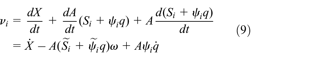
where
The constraint equation usually needs to consider the elastic deformation of flexible body; this is the main difference between rigid-flexible coupling system and multi-rigid system. The form of the constraint equations is a set of nonlinear equations

where

where
Typical constraint modeling method for missile launching system
The typical constraint relation of missile launching system includes hinge, rotation joint, universal joint, and so on. In rigid body dynamics modeling, it is necessary to consider the problem of constraint with clearance. Considering the state of transport and launch of the missile launching system needs to establish the rigid–flexible coupling model—the constraint relationship between the rigid–flexible bodies is the key problem.
25
The revolute joint with gap is not exist in general MS dynamics software, we use double arcs without quality to be equivalent, and the difference of radius equals to the gap between the joint elements. When there is no penetration between the two individual bodies, the impact force is equal to zero; otherwise, the impact force is positive. The elastic collision impact force usually uses a nonlinear spring damper model to calculate. First, define

where


where

The moving joint contact with others, the tangent friction force, and friction torque are generated on the contact surface; we define a friction model based on speed. The relationship between friction coefficient and relative velocity is shown in Figure 1

Relationship between friction coefficient and relative velocity.
From Figure 1, when the absolute value of the relative sliding velocity v is larger than that of the sliding friction critical speed


When the absolute value of relative velocity is less than the static threshold velocity

When the absolute value of relative velocity is between the static threshold velocity

When the absolute value of relative velocity is larger than the dynamic threshold velocity
The parameterized modeling technology of missile launching system
The dynamics simulation for modern mechanical systems requires fast modeling, high efficient, and high simulation accuracy. The general process of dynamics simulation of launch system is as follows. First, three-dimensional (3D) models are built in CAD software, the models are imported into CAE software, and the parameters are set, 26 such as the mass, center of mass, moment of inertia, and other parameters. Second, the constraint relationships are built among parts and adding loads, if more accurate rigid–flexible coupling analysis is needed; the model should be imported into finite element software for generating modal vibration shape and stiffness matrix file; then the original rigid parts are replaced; and finally, rigid–flexible coupling dynamics model is built for launching system. The data transfer between the whole modeling process and the software needs to be completed step by step. If the launching system design scheme changes, the whole modeling process needs to start from scratch, and the whole process has the following disadvantages:
The efficiency of launch dynamics modeling and simulation is low, and the modeling work cannot be reused.
Based on the general GUI of commercial software, the model structure is messy, and the recognizability and the operation efficiency is low.
It is difficult to maintain the consistency of information when there is a change in the models.
Difficulty of data transfer between the software, poor relevance between the parameters, and complicated operation process.
In order to solve the problem of repeat modeling caused by optimization and calculations of multi-design scheme for multiple loading conditions, we can establish design parameter to derive dynamics model creation and update, to realize high-efficiency parameter linkage among design parameters, geometric models, dynamics models, grid models, constraint relations, loadings, and boundary conditions, to achieve dynamics model changed with the change in geometric model cooperatively. The way to realize the geometric and dynamics model is to automatically reconstruct and analyze, which can build key parameter of mapping relationship parameters between geometric model and dynamics model of mechanical system. The parameterized simulation software has the following function: (1) realize automatically build dynamics model and modify parameters; (2) resolve the problem of data transmission interface between CAD and CAE model; and (3) implement synchronous update for geometric model and dynamics model and automatically update the parameters of rigid body, flexible body, and rigid–flexible coupling systems. If this kind of software can be developed, repeated modeling caused by changes in structure size, topological relations, working environment, material properties, and loadings can be avoided, which can improve the efficiency of dynamics simulation. 27
Correlated parametric model
The core of correlated parametric model is to describe the relationship between main driving parameters and functional parameters, which is based on correlation expression of geometric model. The correlated parameter model includes geometric parameters information and logical information. The logical information is realized by adding engineering knowledge through two regulations of KF (Knowledge Fusion) and Expression. The engineering knowledge must be transformed into the form of dynamics parameters which can be identified and modified by computer, and the function of product is finally realized by the geometric and dynamics models. The expressions of the relationship parameters can be established by engineering experience and geometry relationships. The dynamics model can be transformed from the engineering knowledge by these expressions.
The selection of main driving parameters and building parametric relationship
The process of designing mechanical product usually uses top-down or bottom-up design patterns. The design parameters also should have hierarchy characteristics and extract main driving parameters of each layer by layering the modeling parameters (component parameters, parts parameters, and characteristic parameters). The other parameters will be changed with the modification of the main driving parameter. The parameter information of the products at all hierarchy will be expressed completely by the establishment of the hierarchic parameter model, and the corresponding main driving parameters can be established as driving model.
The method of parametric modeling
During dynamics modeling, key parameters are determined and set as changeable design variables based on the function of product and analysis requirement. When analyzing the dynamics of the mechanical system, the value of design variables needs to be input or modified, and the dynamics model will be automatically updated. The simulation software can use the updated dynamics model to calculate the systematic dynamic performance of the mechanical systems under different working conditions. The technical approach of dynamics parametric modeling mainly includes the following: (1) parameterization of the basic dimensions of mechanism and position constraint relationships between components of the model, to make calculation model determined by several key parameters, so as to solve the complicated problem of modeling and (2) parameterization of the key design variables and the calculation model between driven relationship, the connection between the key variables and the dynamic performance optimization is built, the parameters of the design variable values dynamically change in the simulation process, and the constraint conditions should be satisfied to determine the optimal parameter values.
The technical approach of parametric technology of mechanical system CAE/CAD model is shown as Figure 2

Parametric approach of mechanical system.
The software designed in this article is based on the QT development platform, combined with UG/OPEN secondary development language, ADAMS/CMD scripting language, ANSYS/APDL secondary development language, and developed an automatic transfer interface of parameters between the software. The graphical user interface (GUI) is developed by QT, the Multiple Document Interface (MDI) of QT is responsible for the management of running environment and internal control, making visual simulation processing with good human–computer interaction, and is realized by dynamics parameterized modeling of mechanical system. The parametric modeling process is shown in Figure 3.

Flowchart of rigid–flexible coupling parametric modeling.
Design and implementation of parameterized visual dynamics simulation software
In accordance with the general MS visual dynamics software, the parametric visual dynamics simulation software can be divided into three basic modules: pre-processor module, solver module, and the post-processing module. The software uses C++ language combined with Qt framework, integrates Open CASCADE geometry modeling library, provides the basic geometric entity modeling capabilities by calling the Open CASCADE application program interface (API) function, defines the topological structure of MS parameters, and generates MS dynamics calculation parameters, which are read by ADAMS, MBDyn 28 or other solvers to automatically generate dynamics equations and automatically calculate dynamics properties of the system. The simulation results are analyzed and optimized in the form of animation and curve for users.
The architecture design of the software
This article proposed a sort of service-oriented parameterized dynamics visual simulation software, which uses the service-oriented design thought, adopts the method of service to transfer data between the modules, dispatches and manages computing tasks, and make the expression of dynamics modeling, solution, and data storage independent of internal data, to realize seamless joint of UG, Open CASCADE, 29 ANSYS, and Adams. The software is divided into display service layer, data management services layer, and dynamics solution services layer according to object-oriented design thought. The data between these layers are exchanged, shared, transferred, and stored by the service bus. The mission of the service bus also includes the related interface, which makes system solving independent of internal data representation and the seamless integration of solver achieved. Figure 4 shows the design of system architecture:
Modeling and Display Service Layer. This layer provides a user interface for parametric visual modeling and post-processing (simulation results data curve output, 3D model animation).
Data Store Service Layer. This layer provides for managing a variety of modeling and simulation results data, which integrates the interface of CAD, geometric modeling, finite element, and the technology of database, XML.
Multibody Dynamics Solving Service Layer. This layer provides a solver for the MS dynamics calculation. The solver can be ADAMS, RecurDyn, MBDyn, or MSTMM, called according to the needs of users.
Multibody Dynamics Solving Service Bus. The bus is used to invoke different MS dynamics solver for different dynamics analysis according to analysis requirements. The simulation results are sent to Data Store Service Layer by this bus.
Data Service Bus. The bus is used for passing the modeling and simulation results data between Modeling and Display Service Layer and Data Store Service Layer.

Architecture design of the software.
The implementation of GUI of the software
The GUI is mainly used for designing model, executing dynamics simulation, and outputting simulation results. The functional partitioning of pre-processor and post-processor is viewed as in Figure 5, including title bar, menu bar, tool bar, model of the navigation bar, 3D model, animation display window, and simulation information output window.

User interface of the software.
The 3D geometric solid parametric modeling
Parameterization of 3D geometrical model is mainly used for modifying the key parameters of the design model so as to modify the 3D geometric mode. Based on the parametric design, we analyze modeling characteristics of the product abstract characteristic parameters, analyze parameters of the parts, get the correlation model between the parameters of the model, establish relevance and constraint relations between parameters, identify some of the key parameters for the design variables, establish main design variable–driven part, and then realize the management and operation of the part family.
The parametric design based on relatively stable object structure form and topological relation uses a set of main design parameters to express the entire model size values and constrained relationship, whose core is dimension driven. Parametric modeling thought can greatly improve the design efficiency of components, especially for parts with stable form and topological relation, which uses a set of main design parameters to constraint all the size of the geometric sequence and makes main design parameters correspond to controlling size of the object. Giving a different design parameters sequence can drive the original geometric model to generate a new geometric model, to set up the purpose of efficiently creating and modifying model. In order to make a complex part realize parametric design, the part must be analyzed to determine various features of the part, parameter, and the relationship between each other. The process is shown in Figure 6. This software provides the parametric design for emission angle, pitching axis center position, leveling support cylinder position, tire group position, a vertical cylinder pivot position, and other key position, as shown in Figure 7.

Part feature parametric modeling process.

Model parametric interface.
The dynamics model and parametric simulation
The parameterized dynamics model mainly includes the parameterization of rigid dynamics model and coupled dynamics model. By visual interface, parametric results are saved as aview.cmd file of ADAMS and parameter configuration file ANSYS grid generates. 30 The article mainly realizes modification of key parameters of quality of the rigid body, centroid position, moment of inertia, and so on, as shown in Figure 8.

Rigid body model parameterization.
The coupled parameters settings includes the modification and configuration of elasticity modulus Poisson ratio, density, unit dimension, and other parameters, as shown in Figure 9.
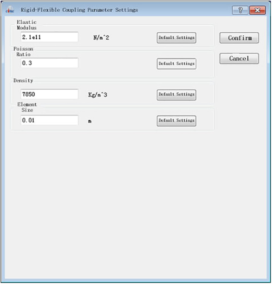
Rigid–flexible coupling parameter setting.
The developed dynamics parameterized simulation visualization software is used to calculate the dynamics simulation of a ground-launched device. Curve output in the post-processing is shown in Figure 10, and the simulation result is output in the form of animation in Figure 11.

Curve output module.

Animation display of simulation.
Design of parameterization of experimental platform
By using MS dynamics method for modeling, the launch vehicle chassis, missile, launch box, landing gear, auxiliary frame, and electric control device of missile launch system can be regarded as rigid body, for the reason of less flexibility. In some parts such as launch vehicle chassis frame girder, longitudinal length of which is longer, in order to improve simulation accuracy, flexible modeling is needed. Figure 12 is the schematic diagram of typical vehicle missile launching system dynamics model.
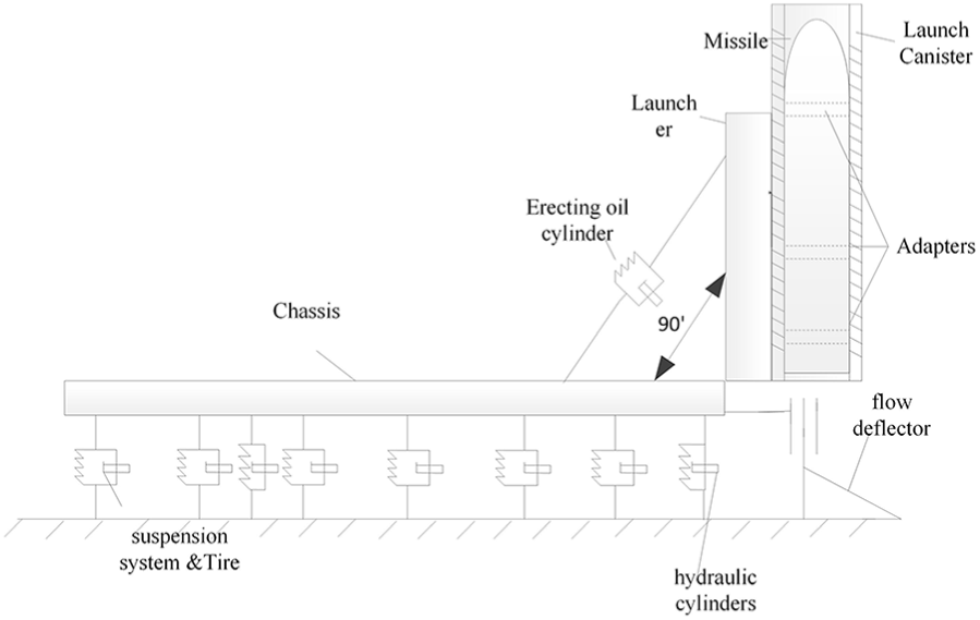
Typical dynamics model of missile launching system.
In order to simulate launch process of the missile, we designed a parametric experimental platform to compare the dynamics simulation results with the experimental results. A parametric 3D geometric models were built in UG, as shown in Figure 13.

The 3D geometric model of the experimental platform.
The experimental platform is mainly composed of the basic unit of the launching system, which includes the chassis simulative system, launching devices, erecting system, tire simulative system, balanced system, and so on. The key parameters can be adjusted to improve the design, such as by adjusting the counterweight block, realizes parametric center of mass and weight of the chassis; through adjustable pivot point to realize the connection point parameterization; and so on.
Parametric design of chassis simulating system
The chassis simulating system mainly composed of the launch chassis frame, launcher rotary trunnion, erecting cylinder low trunnion and launcher cushion block, the low erecting pivot adjustable rails, and counterweight blocks. The shape of chassis simulating system is 3000 mm × 800 mm × 200 mm, which is shown in Figure 14.

The structure of chassis simulating system.
Parametric design of launching device
The launching device comprises two parts of a launch box and a launching frame. The launch box is mainly used for loading and providing support for missiles. The launching frame is mainly used for the installation, sliding, and fixing of the launch box to provide a consistent requirement attitude for the launch box through the erecting device. The structure of the launching device is shown in Figure 15.

The structure of launching device.
A variety of sensors are arranged on the launching device, and the dynamics characteristics of the experimental platform under different conditions are measured by different types of loads on the launching device. A 1385-mm guide rail is installed on the launch frame, and the erecting cylinder low trunnion seat is connected with the different holes on the guide rail to achieve the parameterization of the connection point on the erection system.
Parametric design of erecting system, tire simulating system, and leveling system
The Erecting System. The erecting system is mainly used for regulating the launching angle and withdrawal of the launching device, the launching angle is adjusted in the range of 0°–90°. The erecting system is composed of an electric cylinder, trunnion seat, and pin axle, which is shown in Figure 16.
The Tire Simulating System. The tire simulating system is used for simulating the chassis tire suspension, composed of a FXG type of nonlinear metal spring vibration isolator and the external interface structure, which is shown in Figure 17.
The Leveling System. The main function of the leveling system is to realize the platform leveling and support the experimental platform. The hoisting jack and the external interface structure are the main structures of leveling system, as shown in Figure 18. The leveling system is connected with the launching vehicle chassis by external interface, to realize the horizontal position adjustable by changing different location holes in the range of 0–200 mm.

The structure of erecting system.

The structure of tire simulating system.

The structure of leveling system.
The experimental and simulation verification
Experimental setup
In order to experimentally validate the simulation result, the experimental setup is shown in Figure 19. The experimental setup is composed of high-speed camera (HSC) test point, laser strain–displacement sensor (LSDS) test point, pressure sensor (PS) test point, strain gauge (SG) test point, and inertial measurement unit (IMU) test point:
HSC. The HSCs are installed on the triangle bracket, and the lens is aligned with the cursor point to be measured by adjusting the focal length of the triangle bracket and the camera, and the camera is connected with the data acquisition computer through the cable, to get the displacement response curve of different measurement points.
IMU. The IMU equipment is fixed on the center position of the top end of the erecting frame by the four M6 screws, which is connected with the terminal control computer and GPS antenna through two cables and obtains and stores the data by control computer.
LSDS. Four LSDS is fixed on four brackets, and the brackets are put on the corresponding test point. By adjusting the position of the LSDS on the bracket, the laser spot is located at the corresponding position of the measuring point.
SG. The SG is pasted on the corresponding measuring point position of the experimental platform by the glue and the cloth tape and is connected with the data acquisition device through the communication wire.
PS. The PS is arranged at the bottom of the launching box, which is connected with the bottom of the launching box and the interface of the loading mechanism, respectively, through the screw and the screw rod.
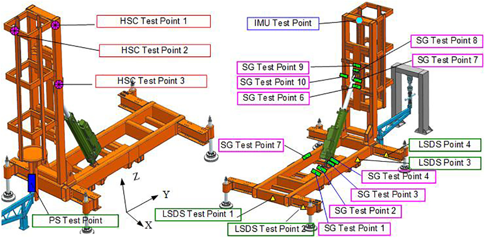
Experimental setup.
Experimental process
Before the experiment, the parameters of the experiment platform are adjusted to meet the experimental conditions required by the experiment. At the same time, according to the requirement of the testing plan, the testing equipment is installed at the location of the corresponding measuring point, and the testing equipment should debug to meet the test state and then load and collect the data; the total process of the experiment is shown in Figure 20 and the testing equipment display interface is shown in Figure 21.

The process of the experiment.

The testing equipment display interface.
Simulation model
The position of the measuring point of the experimental platform is consistent with that of the measuring point based on the rigid-flexible coupling dynamics model. The simulation results were compared to verify the simulation accuracy for the two kinds of simulation models with the experimental results.
First, import the 3D geometric model into the software; define the material properties of each component, the mass and moment of inertia can be obtained; then build connection relationship between each components, add kinematic pair, constraints, and flexible connection; and finally, a complete multi-rigid-flexible dynamics model is formed. The dynamics topological structure of the experimental platform is shown in Figure 22.

Dynamics topological structure of the experimental platform.
Experimental and simulation results and analysis
The experimental measurement and simulation model adopt the same absolute coordinate system: the intersection point of the pitch rotation axis and the symmetrical center of the erecting frame is the origin of the coordinate, the Z axis is perpendicular to the horizontal direction, the Y axis is vertical to the experimental platform, the forward is positive, and the X axis is determined by the right-hand rule.
By compare the experimental results of the single rigid support cylinder erecting state experimental platform with the simulation results of multi-rigid body and rigid–flexible coupling models, the results of the simulation and the experiment are as follows:
Comparison of IMU measurement results and simulation results
The IMU is placed at the top of erectingt frame to measure the pitching angle, and velocity of the pitching angle of the erecting frame was compared with the simulation results of multi-rigid and rigid–flexible coupling dynamics model, as shown in Figure 23.
Compared with the multi-rigid body model, the pitching angle of the rigid–flexible coupling dynamics model simulation results is in good agreement with the experimental results, the factors of the structure of testing equipment gap, and the IMU experiment platform in actual acquisition precision; the experimental results decay faster.
Comparison of HSC measurement results and simulation results
Three HSCs placed at test points 1, 2, and 3 on the top of the erecting frame are shown in Figure 18. Figure 24 gives the displacement and velocity of Y-direction of the top of erecting frame.
The simulation results of two kinds of dynamics models are found in good coincidence with the results of HSC, especially for the first peak of displacement and velocity curve. Because most parts of the multi-rigid and rigid–flexible coupling dynamics model are regarded as rigid bodies, and ignoring the gap between the components and the deformation and damping of the parts, the simulation results are slightly different from the experimental results in the curve of the attenuation trend.
Comparison of LSDS measurement results and simulation results
The LSDS is arranged on the front and back support legs of the experimental platform, mainly used for measuring the front and rear ends of the vertical displacement of experimental simulating chassis, as shown in Figure 25.
Comparison of SG measurement results and simulation results of flexible body
Figure 26 shows the experimental and simulation results of strain change curve of maximum stress point on the upper and lower trunnion of the erecting cylinder. The upper and the lower trunnion seat connecting plate of erecting cylinder is flexibly processed in the rigid–flexible coupling dynamics model.

Output pitching angular and velocity of erecting frame: (a) pitching angle and (b) pitching angular velocity.
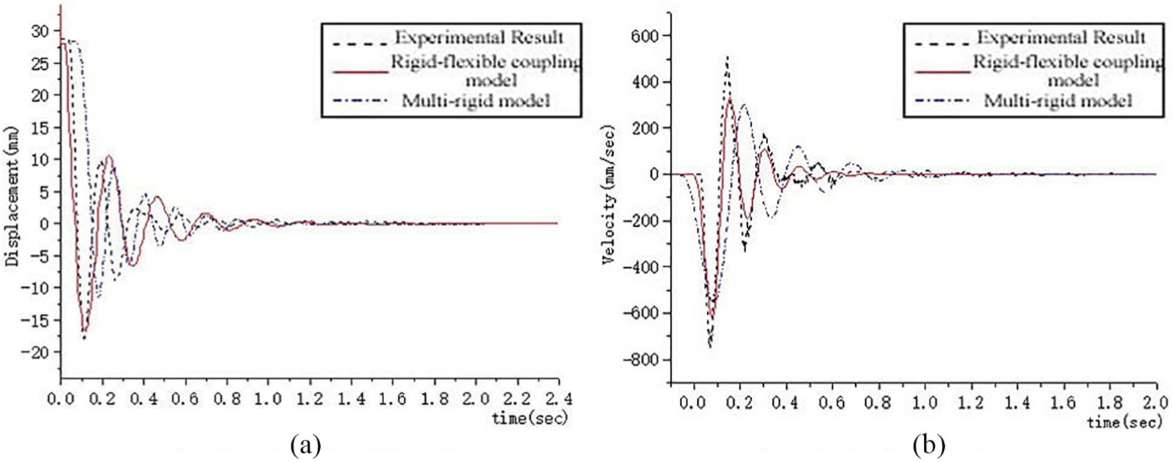
Output displacement and velocity of Y-direction erecting frame: (a) displacement of Y-direction and (b) velocity of Y-direction.
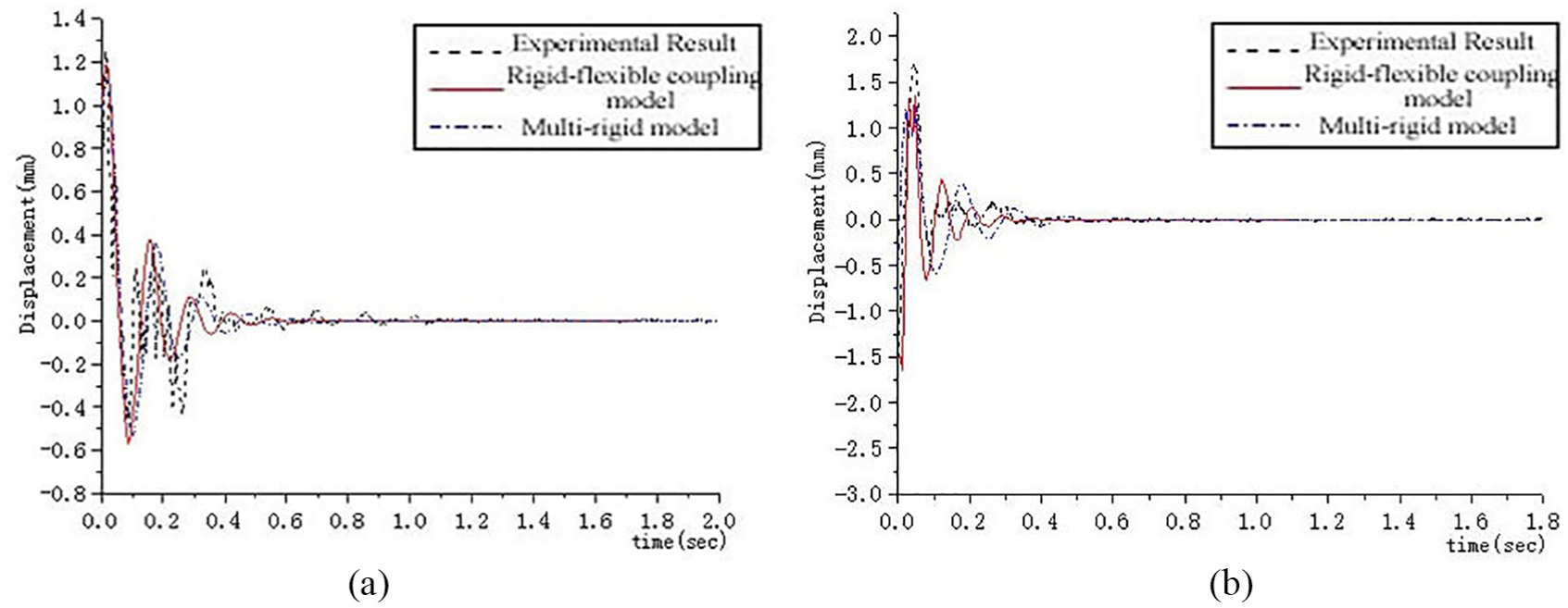
Output displacement of Z-direction of the right leg: (a) displacement of Z-direction of the right rear leg and (b) displacement of Z-direction of the right front leg.

Output strain of the pivot of erecting cylinder: (a) upper pivot of erecting cylinder and (b) lower pivot of erecting cylinder.
By comparison, the experimental results of upper and lower pivot of the erecting cylinder are found in good coincidence with the simulation results by using rigid–flexible coupling model. The simulation and experimental results show that the flexible deformation of the trunnion seat connection plate on the erecting cylinder is obvious and cannot ignore flexible deformation in designing dynamics model of the connection plate. The rigid–flexible coupling model can more accurately simulate the experimental dynamics model.
The following conclusions can be drawn from the above experiments and simulation results:
The overall trend of the simulation results of multi-rigid and rigid–flexible coupling dynamics model is consistent with the experimental results of IMU, HSC, LSDS, and SG. The vibration amplitude is in the same order of magnitude as the difference of the vibration frequency is low than 20%.
In the dynamics modeling, the gap between the components is neglected, and the simulation results and the experimental results have some deviation;
Because only considered the rigid-flexible coupling simplified dynamics model of the upper and lower connecting plates of the vertical cylinder, the loading force of the whole model becomes small, resulting of a small flexible deformation, and the simulation results of rigid-flexible coupling becomes larger in magnitude than the multi-rigid model.
Because of the most components of the dynamics model simplifies as rigid bodies and ignores the effects of the stiffness and damping of the components themselves, the simulation results of attenuation rate of the dynamics model is faster than that of the experimental measurement results, and the amplitude of steady attenuation phase is also small.
Through the parametric experimental platform in this article, the rationality of the simplification of simulation models and parametric settings is verified, and the accuracy of simulation results is under different conditions.
Discussion
The research work in this article as an important part of a base of national defense research projects, for the circumstance of the present domestic lacking dedicated and efficient parametric simulation software of mechanical system dynamics and in order to meet the demand of designing scheme with the fast iterative optimization, by applying multibody dynamics method, object-oriented technology, component technology, virtual prototype technology, CAD technique, Integrated QT, Qwt, Open CASCADE, Python (provide command-line operations such as parametric modeling and simulation control), and other open source components, has designed and developed the dynamic parameterized visualization simulation software. The software creatively makes the organic combination of the parameterized geometric model and dynamic model, solves the CAD and CAE bidirectional parameter driving, realizes the design parameters of geometric model and dynamics model seamless transfer, and establishes a service-oriented software architecture, which by solving the service bus and data bus service can automatically call a variety of dynamics solver, drive a variety of modeling software interface, and distribute modeling solving data to provide important digital platform for fast visualization simulation, design, and analysis of all kinds of complex mechanical system dynamics.
Footnotes
Acknowledgements
H.Y. and Z.Z. conceived and designed the experiments; F.X. contributed to reagents/materials/analysis tools; H.Y. and W.X. contributed to the simulation work; D.Q., H.Y., and C.P. translate and review the language; and H.Y. and W.X. contributed to the writing of the manuscript. All authors reviewed the manuscript.
Handling Editor: Xihui Liang
Declaration of conflicting interests
The author(s) declared no potential conflicts of interest with respect to the research, authorship, and/or publication of this article.
Funding
The author(s) disclosed receipt of the following financial support for the research, authorship, and/or publication of this article: This work was supported by the Basic Scientific Research of National Defense (JCKY201606C001, JCKY2017204B011), the Open Program of National Engineering Laboratory for Modeling and Emulation in E-Government (MEL-16–02), and Chinese Defense Advance Research Program of Science and Technology (41401030301).