
Abstract
The large amount of fine and light particles in the mine water are difficult to be removed using the traditional separator. In order to improve the separation efficiency, this article presents a new type of compact cone-plate clarifier with which a hybrid process combining magnetic flocculation separation with hydrocycloning can be achieved for sewage treatment. Addition of cone-plates to the elongated vortex finder provides more possibility for small magnetic flocs to aggregate and form into large flocs as well as increase the sedimentation area. The numerical simulation indicates that the cone-plate is conducive to the agglomeration of small particles in the cylindrical body and favorable for flocs to precipitate steadily in the conical part of the clarifier. Further comparative experiment verifies the effectiveness of the cone-plates. Then, the influence of cylinder height, insertion depth, and spacing of cone-plates on the water quality of the clarifier have been researched, and the optimum structural parameters have been determined. With the optimum parameters—a cylinder height of 600 mm, a cone-plate insertion depth of 400 mm, and plate spacing of 20 mm, a property index of 93.71% for suspended solids removal and 70.17% for turbidity decrease has been obtained for the mine water treatment.
Introduction
Water pollution has become a major problem in recent years.1,2 For example, the direct drainage of mine water leads to severe soil pollution and a large amount of water waste. Removing the suspended solids (SS) is an important goal of mine water treatment.3–5 During this process, large amount of fine and light particles in the mine water are difficult to deal with. The formation of large particles after the aggregation of fine particles is an effective method to solve the problem. In previous research works, coagulation–flocculation technology has been commonly used for this purpose, based on destabilizing the colloidal suspension of the particles with coagulants and then causing them to agglomerate with flocculants, accelerating their separation and thereby clarifying the effluents. 6 Jang et al. 7 applied high-molecular-weight long-chain polymers to the flocculation of suspended fine particles. With small dosage, they could enhance the precipitation speed of flocs and reduce sludge production effectively. Currently, numerous efforts and methods8–11 have been conducted to solve the problem of fine particles processing, such as electrolytic coagulation, hydrophobic flocculation, and magnetic flocculation. Among these technologies, magnetic flocculation separation (MFS) has been more and more employed in sewage treatment attributing to its advantages of simple preparation, short processing period, and low cost.12,13 Li and Wang 14 researched a fly-ash-based magnetic coagulant to accelerate the flocculation and sedimentation. Bai and colleagues15,16 investigated micro-fine minerals recovery from reductive iron ore by ultrafine grinding-MFS and obtained an iron recovery of 81.45%. Therefore, magnetic flocculation has turned out to be a promising method for treatment of fine particles in mine water.
In addition to the coagulation and flocculation, some hybrid processes have also been proposed. Menezes et al. 17 studied a coagulation and flocculation process in conjunction with a dynamic separator based on a swirling motion to remove solid phase from water phase. Rubio and Rosa 18 used a flocculation and flotation process to produce aerated polymeric flocs of an emulsified oil dispersion followed by separation in a centrifuge cell. Bamrungsri et al. 19 and Puprasert et al. 20 presented a hybrid process combining coagulation, flocculation, and hydrocycloning. The results have shown that the centrifugal forces created by the tangential flow injection lead to strong velocity gradients at the wall, which promote the coagulation and flocculation phenomenon. Efficiencies of 61% ± 4% for turbidity decrease and 77% ± 20% for SS removal were obtained using the compact and efficient process.
From previous studies, a hybrid process combining MFS with hydrocycloning should be efficient and worth further attention. While seldom research focuses on the equipment improvement, this article proposes a new type of compact cone-plate clarifier (see Figure 1). It is composed of feed inlet, cylindrical body, conical part, vortex finder, and spigot. Compared to a traditional hydrocyclone, a series of cone-plates are evenly equipped with the elongated vortex finder. On one hand, the effect of centrifugal force accelerates the sedimentation of magnetic flocs; on the other hand, the cone-plates can increase the subsidence area and improve separation efficiency. The working principle of the clarifier is that sewage first mixes with magnetic seeds, coagulants, and flocculants in the static mixer and then enters into the clarifier along the tangential inlet direction. The velocity gradients caused by centrifugal force accelerate the collision of small flocs and allow close approach and aggregation, generating bigger magnetic flocs with quick precipitation under the action of centrifugal field and gravity field. Finally, the magnetic flocs flow downward into the spigot. Although some small flocs entrained in the inner vortex flow may flow toward the overflow pipe, owing to the blocking effect of cone-plates, they will collide, accumulate, and rise continuously to form large flocs, as shown in Figure 1. After reaching a certain weight, the large flocs fall back into the underflow due to gravity. By this way, the number of fine particles or flocs flowing into the overflow can be reduced effectively and the separation efficiency will be improved.

Schematic of cone-plate clarifier.
The general objective of the study is to investigate the performance of the cone-plate clarifier with structural parameters shown in Table 1. In order to predict the effectiveness of promoting particle settlement by adding the cone-plates in the traditional clarifier, the flow field of the clarifier with and without cone-plates is simulated and compared using computational fluid dynamics (CFD) software. The effects of structural parameters, including cylinder height, insertion depth, and spacing of cone-plates on the flow field of the new clarifier are also simulated. Then, the comparative tests of the two kinds of clarifier are carried out with respect to SS and turbidity removal efficiency, which can also verify the simulated prediction. Finally, the separation performance of the cone-plate clarifier is tested.
Structural parameters.

Numerical simulation
Geometric model and mesh
The geometric model of the clarifier was built with SolidWorks software. The bottom center is chosen as the origin of coordinates and the three-dimensional model of the fluid domain is built. Meshing was of importance for obtaining meaningful numerical results in CFD simulation. In this study, the computational domain was divided by tetrahedral grids for numerical stability and efficiency. The model and the mesh of the traditional clarifier (without cone-plates) and the cone-plate clarifier are shown in Figure 2. The structural parameters are in correspondence with Table 1.

Model and mesh of fluid domain: (a) traditional clarifier and (b) cone-plate clarifier.
The grid independency check was undertaken to guarantee the simulation accuracy and reasonable computation cost. Figure 3 presents the tangential velocity distribution at the middle cross section of the traditional clarifier cylinder for four different mesh sizes (150, 200, 350, and 500 K). It is concluded that when the mesh size exceeded 350,000, the computational results were independent of the mesh size used. Therefore, about 350,000 grids were used in this computation.

CFD predicted tangential velocity by four mesh sizes.
Boundary conditions and solver settings
Assume that the solid particles were uniformly dispersed in the fluid with a concentration of 0.1%–0.3%. The mutual effect between particles could be omitted owing to the low concentration. Models of the liquid–solid, two-phase, flow have been introduced in previous studies.21,22 In this study, turbulence was modeled using reynolds stress model (RSM), which is suitable for an isotropic turbulence such as in a hydrocyclone flow. Transport equations of Reynolds stresses terms were written as follows

Here, Pij is stress production, DT, ij is turbulent diffusion, DL, ij is molecular diffusion, εij is dissipation, φij is pressure strain, and Fij is production by system rotation


The model requires the following empirical constants:
DPM model was chosen to simulate the particle trajectory. The motion of a particle was described by the stochastic Lagrangian multiphase flow model. Assume the volume fraction of dispersed phase was very low, and the particle–particle interactions and their effect on the liquid phase were negligible. The particle motion equation could be written as follows


Here,
The “velocity-inlet” was used at the feed inlet, and the inlet velocity was 1.6 m/s. The turbulence intensity was 5%. The hydraulic diameter was 16.2 mm.
The “pressure-outlet” condition was set at both outlets. The pressure at the two outlets (vortex finder and spigot) was 1 atm, corresponding to the ambient atmospheric pressure.
No-slip wall boundary conditions and the standard wall surface function were selected.
The implicit separation algorithm was adapted to velocity coupling, and the pressure equation was solved by Semi-Implicit Method for Pressure Linked Equations (SIMPLE) method.
Simulated results
The velocity vector
Obviously, vortex can be found in the conical part of the traditional clarifier (Figure 4(a)), while fewer vortexes appear in the cone-plate clarifier (Figure 4(b)). The existence of a number of vortexes in the traditional clarifier is easy to disturb normal precipitation of magnetic flocs, resulting in small flocs flowing into the overflow with rising water, further leading to quality variation of the overflow water. Such phenomenon will not occur in the new type of clarifier, which is conducive to the smooth sedimentation of the flocs, ensuring the steady water quality of the overflow. Similar to the conical part, the number of vortexes in the cylindrical body is also obviously reduced after adding cone-plates in the vortex finder.

Velocity vector in two kinds of clarifiers: (a) traditional clarifier and (b) cone-plate clarifier.
The shear force
Figure 5 presents the shear force distribution. The overall shear force intensity in the traditional clarifier is bigger, with maximum value occurs near the bottom of vortex finder. It should be noticed that the increase in the shear force might cut the well-formed flocs and then the broken small flocs will enter the overflow; as a result, the outlet water quality will be deteriorated. In contrast, the shear force in the cone-plate clarifier appears smaller, especially at the conical part. From the point of view of flocculation precipitation, this is favorable.

Comparison of shear force: (a) traditional clarifier and (b) cone-plate clarifier.
The turbulent kinetic energy
Select two cross sections in the cylindrical and conical parts and compare the turbulent kinetic energy of the two kinds of clarifiers. From Figure 6(a), in the cylindrical body, the turbulent kinetic energy in the cone-plate clarifier is bigger, which increases the collision frequency of small broken flocs or unchanged fine particles. Obviously, it is conducive to the coagulation and flocculation process. From Figure 6(b), inversely, the turbulent kinetic energy in the conical part becomes small in the cone-plate clarifier. However, this is also a desirable result because the low turbulent kinetic energy has a good laminar effect, which is beneficial for flocs to precipitate stably.

Comparison of turbulent kinetic energy: (a) cross section in the cylindrical body and (b) cross section in the conical part.
The particle trajectory
Assume 5 μm particles represent the fine flocs and compare their trajectory in different clarifiers. As shown in Figure 7(a), in the traditional clarifier, most of the fine 5 μm particles enter into the overflow, resulting in an increase in the solid content and the deterioration of water quality. On the contrary, most of fine particles flow into the underflow after inserting the cone-plates (see Figure 7(b)). This phenomenon can be interpreted as that, during the upward process of fine particles, the cone-plates hamper their motion. Thus, these particles run slowly between plates. Because more residence time is provided, it is easy for them to collide, agglomerate, and form into big flocs and then enter into the underflow.

Comparison of 5 μm particle trajectory: (a) traditional clarifier and (b) cone-plate clarifier.
Effect of structural parameters on the flow field
In order to investigate the effect of structural parameters on the flow field, further simulation including different cylinder heights, insertion depths of cone-plate and cone-plate spacing were carried out.
Cylinder height and velocity distribution
Assume the different cylinder heights as 400, 500, 600, and 700 mm. Figures 8 and 9 give the tangential and axial velocity distributions at the middle cross section of the cone-plates and at the section z = 155 mm (the conical part of the clarifier), respectively. From Figure 8(a), the tangential velocity decreases obviously as the cylinder height increases, and the maximum value of tangential velocity is nearly the same for cylinder heights 600 and 700 mm. Figure 8(b) shows that the tangential velocity at the conical part of the clarifier decreases slightly as the cylinder height increases from 600 to 700 mm. The axial velocity presents similar tendency in Figure 9(a), while it fluctuates at the conical part. When the cylinder height reaches 700 mm, the axial velocity exhibits smaller fluctuation and better symmetry, as shown in Figure 9(b). Therefore, increasing the cylinder height is beneficial for prolonging the sediment time attributed to the decreased tangential and axial velocities.

The tangential velocity distribution versus cylinder height: (a) cylindrical body and (b) conical part.

The axial velocity distribution versus cylinder height: (a) cylindrical body and (b) conical part.
Insertion depth of cone-plate and turbulent kinetic energy
Figure 10 shows the contour of turbulent kinetic energy in the clarifier as the insertion depth of cone-plate increases from 250 to 400 mm. Here, the insertion depth refers to the distance between the top cross section to the bottom cross section of the last cone-plate. The turbulent kinetic energy keeps at a low value in the areas below the cone-plates. At the upper part beyond the first cone-plate, it presents the same tendency as the insertion depth increases. It can be assumed that the flocculation process can be reinforced effectively due to the enlarged space at the top area above the cone-plates.
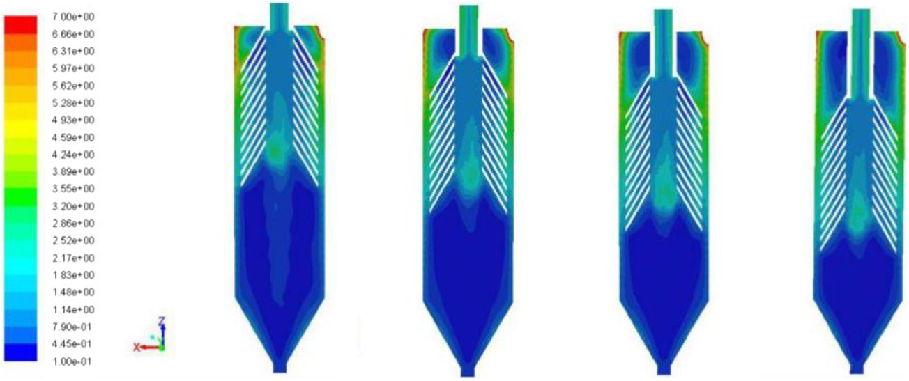
The turbulent kinetic energy versus insertion depth of cone-plate.
Cone-plate spacing
The fluid region changes once the cone-plate spacing increases or decreases, causing the variation of velocity distribution accordingly. It is assumed that the particles may have more opportunity to collide with each other and form flocs by decreasing the cone-plate spacing. However, the staying time of particles, which is affected by the velocity distribution, is also need to be considered. Figures 11 and 12 illustrate the tangential and axial velocities at the cylindrical body and conical part. The velocity distribution at the cylindrical body shows obvious decreasing tendency as the cone-plate spacing decreases, attributing to the increasing resistance force. It is advantageous for prolonging the staying time for flocs. In comparison with the cylindrical body, the velocity shows little variation at the conical part.

The tangential velocity distribution versus cone-plate spacing: (a) cylindrical body and (b) conical part.
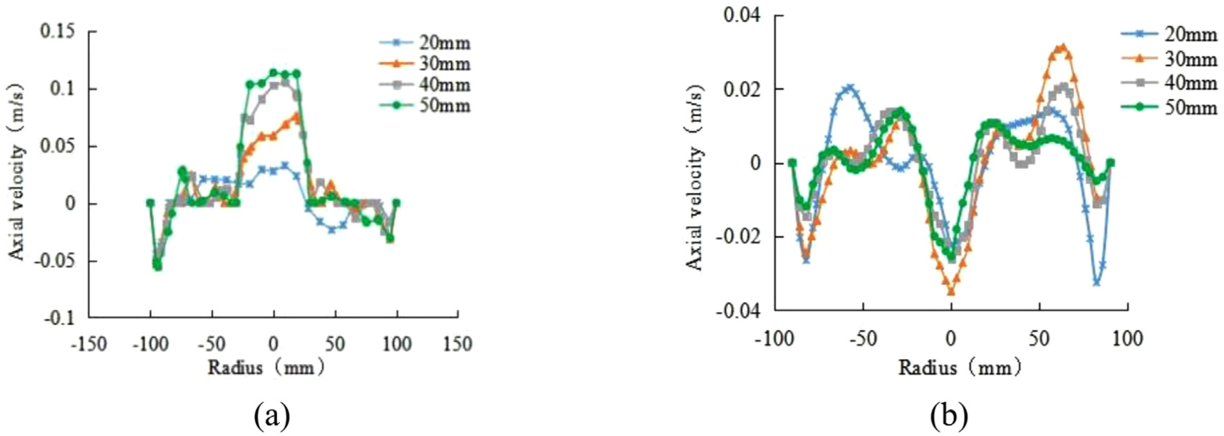
The axial velocity distribution versus cone-plate spacing: (a) cylindrical body and (b) conical part.
From above simulation, the flow field variation indicates better separation performance by adding cone-plates in the clarifier, increasing the cylinder height, increasing the insertion depth of cone-plates, and decreasing the cone-plate spacing. Further experiments are carried out in order to verify the separation performance of the clarifier.
Experiment
Materials and detecting equipment
Take fly ash as a raw material to prepare wastewater. Denote the particle size by D. Analyze the particle size using BT-9300S laser particle size distribution (Dandong Baxter instrument Co., Ltd) (see Table 2). With 78.31% of the content smaller than 20 μm, the material was too fine to be removed by traditional precipitation method.
Particle size distribution.

The properties of the sewage are listed in Table 3. The SS concentration was measured with detector SS-1Z. The turbidity was obtained by portable turbidimeter WGZ-1b. The pH value and zeta potential were measured with a pH meter and micro-electrophoresis JS94H, respectively. In later experiments, the particle number was recorded by HACH 2200 PCX Particle Counter.
Properties of sewage.

SS: suspended solids.
Select polyaluminium chloride (PAC) as the coagulant and polyacrylamide (PAM) as the flocculants. Use magnetite powder to form magnetic flocs. According to the jar test, the optimum quantity of the coagulants, flocculants, and magnetite powder are PAC 60 mg/L, PAM 6 mg/L, and magnetite powder 500 mg/L, respectively.
Test system
The schematic of flowchart and the photograph of the test rig are shown in Figures 13 and 14, respectively. The test rig was mainly composed of the cone-plate clarifier, static mixer, submerged pumps, peristaltic pump, and pipeline. The flowchart is described as follows: the sewage was transferred into the piping system by the submersible pump. As it flowed through the first level of static mixer, PAC and magnetite powder were added into it. Then, PAM was added subsequently in the second level of static mixer. Using the efficient hybrid effect of static mixer, the magnetic flocs were formed initially and introduced into the clarifier for further flocculation and sedimentation.
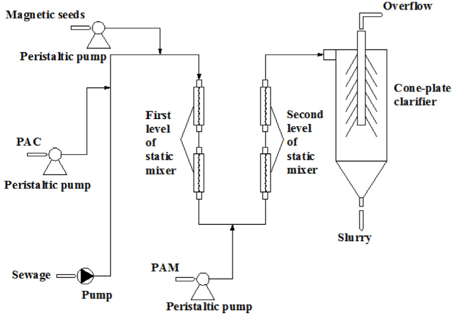
Flowchart of the test system diagram.

Photograph of test rig.
During the experimental process, the PAC, PAM, and magnetite powder were added by peristaltic pump. Sample outlets were set at the overflow connection in order to analyze the water quality.
Results and discussion
Comparative experiment
The comparative experiment was carried out by setting equal handling quantity for the two kinds of clarifier. From the property indexes (Table 4), the SS removal and the turbidity removal increase by 50.65% and 42.88%, respectively, after adding the cone-plates. Meanwhile, the pH value and zeta potential decrease 0.22 and 0.75, respectively. The particles number in the overflow is reduced from 7120 to 3595 mL−1. The data demonstrate the effectiveness of cone-plates in the aspect of improving separation performance of the clarifier. This can be explained as that the existence of cone-plates shorten the precipitation distance and increase the precipitation area, leading to rapid sedimentation of magnetic flocs.
Comparison of water property indexes.

SS: suspended solids.
The effect of cylinder height
The cylinder height of clarifier can influence the sedimentation distance of the flocculating particles, thus affecting the whole separation performance. Usually, the higher the cylindrical body is, the more sufficient time the flocculating process experiences. In this experiment, different cylinder heights including 400, 500, 600, and 700 mm were tested individually. By adjusting the insertion depth of the vortex finder, the distance between the last cone-plate and the bottom spigot kept unchanged.
Figure 15 reveals the effect of cylinder height on the overflow water quality. As the cylinder height increases from 400 to 600 mm, the SS removal rate increases from 77.62% to 83.23%, and the turbidity removal rate increases from 46.21% to 50.52%. The number of particles is reduced from 4092 to 3651 mL−1. The results imply that the sedimentation time of the flocs is effectively extended due to the increase in the cylinder height. When the cylinder height exceeds 600 mm, although the particles number decreases obviously, the changing tendency of SS removal (from 83.23% to 84.18%) and turbidity removal (from 50.52% to 51.25%) becomes weak; therefore, in the subsequent experiment, the cylinder height is kept as 600 mm.

The effect of cylinder height on separation performance.
The effect of insertion depth of the cone-plate
The insertion depth of the cone-plate influences the particle trajectory, thus affecting the flocculation process. In the experiment, other parameters are kept unchanged and the insertion depth was changed by adjusting the distance between the bottom of vortex finder and the upper cover of the clarifier, including 250, 300, 350, and 400 mm, respectively.
The influence of insertion depth on the water quality is presented in Figure 16. As the insertion depth increases from 250 to 400 mm, the SS removal rate increases from 80.32% to 90.25% and the turbidity removal rate increases from 49.14% to 58.92%. The number of particles is reduced from 3992 to 2951 mL−1. It is obvious that when the insertion depth is too shallow, the close distance between the feed inlet and the plate makes it possible for fine flocs to be brought by upward water directly into the overflow, resulting in poor water quality. However, if the cone-plates are inserted deeply, the upward fine flocs in the conical part can reach the cone-plate rapidly. It should be noticed that the flocculation occurs mainly in the conical zone and it is easier for fine flocs to collide with each other and aggregate to form larger flocs by aid of cone-plates. Thus, it is conducive to improve the separation efficiency.

The effect of insertion depth on separation performance.
The effect of cone-plate spacing
The cone-plate spacing can change the collision probability of flocs and affect the fluctuation of fluid. Keep the distance between the bottom spigot and the last cone-plate unchanged, and increase the cone-plate spacing to 20, 30, 40, and 50 mm, respectively.
Figure 17 reports the influence of cone-plate spacing on the water quality. Reducing the cone-plate spacing has brought satisfied results. The SS and the turbidity removal rates increase from 73.21% to 83.32% and from 45.73% to 53.17%, respectively. The number of particles decreases from 4051 to 3292 mL−1. The possible reason may be that the shortened cone-plate spacing increases the frequency of fine flocs contact with the plate, providing more chance for fine flocs to collide and accumulate. At the same time, the hindrance of the plates slows down the flow rate, thus the flocculation particles have sufficient sedimentation time.
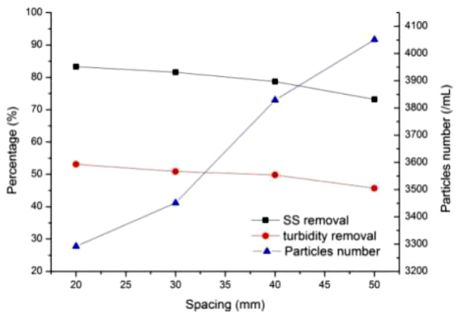
The effect of cone-plate spacing on separation performance.
Experiment with mine water
According to the former experiments, the optimal quantities of the significant variables were determined as a cylinder height of 600 mm, a cone-plate insertion depth of 400 mm, and spacing of 20 mm. Then, a sample of practical mine water was processed by the clarifier with optimized structural parameters. Figure 18 presents the contrast photograph before and after treatment. Table 5 lists the detail property indexes. 93.71% for SS removal and 70.17% for turbidity decrease are obtained. The SS and turbidity reach 20–30 mg/L and 30–40 NTU, respectively, verifying that most of the fine particles have been removed, and the water quality was improved obviously.
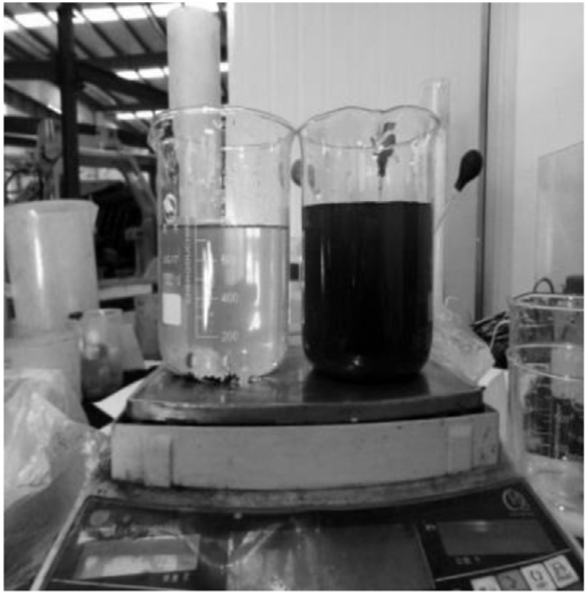
Water quality before (right) and after treatment (left).
Comparison of water quality parameters before and after treatment.

Conclusion
A compact cone-plate clarifier combining MFS with hydrocycloning has been proposed for fine particle removal during treatment of mine water. As the cone-plates are added in the elongated vortex finder, most upward small flocs collide, accumulate, and fall down into the underflow, which can effectively improve the overflow water quality.
Numerical simulated results show that the shear force decreases and the turbulent kinetic energy increases in the cylindrical body of the clarifier, which is conducive to the aggregation of the small flocs into the larger ones. Whereas the turbulent kinetic energy in the conical section decreases, which is favorable for flocs to precipitate steadily. The particle trajectory of 5 μm particles indicates that fine particle content in the overflow is reduced.
The cylinder height, insertion depth, and spacing of cone-plates influence the water quality of the clarifier. With the increase in the cylinder height and insertion depth, and the decrease in the plate spacing, the removal rate of SS and turbidity increases gradually and the number of particles in the overflow is reduced.
With the optimum structure parameters—a cylinder height of 600 mm, a cone-plate insertion depth of 400 mm, and plate spacing of 20 mm, a property index of 93.71% for SS removal and 70.17% for turbidity decrease has been obtained for the treatment of mine water.
Footnotes
Handling Editor: Jiin-Yuh Jang
Declaration of conflicting interests
The author(s) declared no potential conflicts of interest with respect to the research, authorship, and/or publication of this article.
Funding
The author(s) disclosed receipt of the following financial support for the research, authorship, and/or publication of this article: This research was funded by the National Natural Science Foundation of China (No. 21276145) and Natural Science Foundation of Shandong Province (ZR2016EEM37).