
Abstract
Kinematics and dynamics are the most important and basic tool for robot research. With the help of computer technology and the respective advantages of three kinds of software, a new method of co-simulation of parallel robot based on multi-platform is proposed, and the mechanical model of multi-body system of 3-revolute-prismatic-spherical parallel robot is established. According to the mechanical analysis of the parallel robot, the rigid-flexible coupling analysis method is adopted. The displacement error shows a periodic change with a period of 4.2 s and the maximum error is
Keywords
Introduction
Since the 20th century, the field of robotics has been changing with each passing day, and it is in a period of vigorous development. The application of robots represents the development level of national industrial automation. At the same time, the development level of robots also directly reflects the advanced level of national science and technology. Robot involves many disciplines such as electrical engineering, computer science, sensing technology, artificial intelligence, image recognition, bionics, control engineering, kinematics, dynamics, and mechanism. Among them, kinematics and dynamics are the most important and basic tool for robot research.1,2
Parallel robots are widely used in assembly production lines, parallel robotic machine tools, flight simulators, spacecraft docking mechanisms and its ground test equipment, satellite antenna reversing devices, naval vessel observation stations, astronomical telescope tracking and positioning systems, and dynamic entertainment platforms. 3 Among them, the research of parallel robot machine tool has been the focus of research all the time.
The parallel robot with multi-closed-loop mechanism as its main structure has the remarkable characteristics of large structural rigidity, good stability and strong bearing capacity. Moreover, the motion error at the end is not the accumulation of errors in all joints, which improves the motion accuracy. 4 In addition, it is easy to implement redundant driving of the robot. Because of this, parallel robots have high application value in high precision, high speed, heavy load, and other work fields.5,6
Computer-aided design (CAD) greatly increases production efficiency and reduces production costs. Pro/E (Pro/Engineer) is one of the most widely used 3D (three-dimensional) CAD software in the world. Its many functions include product 3D design, engineering drawing, mold development, CAM (computer-aided manufacturing), and even dynamic simulation and finite element analysis. Its strengths are solid modeling, but it is more difficult to perform professional high-precision analysis or to calculate in the case of complex boundary conditions. DM Gan et al. 7 are based on a new metamorphic parallel mechanism based on a reconfigurable revolute (rR) joint and the mechanism consists of three rRPS (rR joint-prismatic joint-spherical joint) limbs. Using the limb geometric constraint model, analytical forward kinematics is solved in a unified way for two working motion types, pure rotation (3R) motion and one translation and two rotation (1T2R) motion. Reciprocal screw-based Jacobian is obtained for singularity analysis which is then used for singularity-free workspace analysis. Based on those, maximum singularity-free workspace and kinematics performance-based criteria are applied in optimizing basic mechanism parameters considering input and passive joint limitations. Z Zhen uses two methods to study the rapid modeling and collaborative simulation of parallel robots. One approach is to transfer the 3D SOLIDWORKS model into MATLAB/SIMULINK model. Another method is to import the 3D model files of Solidworks into ADAMS. ADAMS and SIMULINK work together as a simulation platform. The results show that the two methods provide a meaningful simulation platform for studying the control strategy of parallel robot. 8
ADAMS is software specifically developed for the virtual prototype of mechanical products. XY Qi establishes the mathematical model of the spatial 3-revolute-prismatic-spherical (RPS) parallel mechanism, analyzes the positional posture of the mobile platform by using the closed-loop equation, and carries out the motion simulation by using ADAMS software, which makes sense in kinematical performance of spatial 3-RPS parallel mechanism. 9 ADAMS studies the kinematic relationship and dynamic relationship of complex systems. It is based on the calculation of multi-body system dynamics, combined with high-speed computer to simulate the product and obtain various experimental data to help designers find and solve problems. ANSYS is a very powerful finite element software that combines structural, thermal, fluid, electromagnetic, and acoustic analysis. It has been widely used in industrial production and scientific research. However, its 3D modeling ability is still lacking; it is time-consuming to model by Boolean operation of point, line, and surface; and it is more powerless to set up complex surface.10,11
By analyzing the advantages and disadvantages of the three kinds of software, we can make use of their respective advantages to realize the design, analysis, and optimization of engineering projects quickly. The specific process is creating a 3D model, assembly, and doing some simple analysis in Pro/E, such as interference checking or simple kinematic analysis. The model is imported into ADAMS to complete the setting of the simulation parameters to make a virtual prototype, and the kinematics and dynamics analyses are performed to obtain the data. The key model parts that need to be analyzed are imported into ANSYS. Sometimes the data obtained in ADAMS can be used as a boundary condition for finite element analysis, and key data such as stress values can be calculated for strength check. If the simulation results in ADAMS and ANSYS do not meet the requirements, return to Pro/E to re-modify the design until it meets the requirements.12–14
In this article, a new method of multi-platform joint simulation of parallel robot is proposed by establishing the internal relations of the three software, and a multi-body system mechanical model of 3-RPS parallel robot is established. For the mechanical analysis of the parallel robot, the rigid-flexible coupling analysis method is used, and the displacement change and error curve of the robot end, the dangerous part of the structure, and the stress change curve are obtained. Co-simulation based on multi-platform improves the accuracy of dynamic response analysis of parts under dynamic load and provides important theoretical basis for simulation analysis of parallel robots.
Data transfer between multiple software
The data transfer between Pro/E and ADAMS can be achieved by the interface module Mech/pro2005. The model is assembled under the interface of Pro/E, and each rigid body is defined by the interface module. After unifying the units, it can be transmitted to the ADAMS/View through the interface module for operation. Parameters such as materials, joints between parts, and gravity are defined, and the model is analyzed. The interface module Mech/pro2005 implements a seamless connection of the two kinds of software. It can also be converted by the intermediate format of The Initial Graphics Exchange Specification (IGES), but the interface module is recommended. Data transfer between Pro/E and ANSYS can be achieved by integrating ANSYS directly into Pro/E. The co-simulation design flow is shown in Figure 1.

Design flow of joint simulation.
Mech/pro2005 module
The Mech/pro2005 module is a bridge between Pro/E and ADAMS. Through this module, Pro/E and ADAMS can be seamlessly connected, so that Pro/E users do not have to quit their application environment; then the assembly can be defined as a mechanism system according to its motion relationship. The kinematics of the system is simulated and the interference check is carried out to determine the position of the motion lock and to calculate the force between the motion pairs.
The Mech/pro2005 module is created with the PRO/DEVELOP tool, so Pro/E users can accurately build 3D mechanical system models in their skilled CAD environment and simulate their motion performance. Through simple operation, data can be transferred to ADAMS and comprehensive dynamic analysis can be carried out.
ADAMS/View module
ADAMS/View is one of the core modules of the ADAMS family of products, a user-centric interactive graphics environment. It provides a direct-to-user basic operational dialog environment and pre-processing capabilities for virtual prototyping, including prototyping modeling and various tools, data entry and editing of prototype models, and automating programs for solvers and post-processing. ADAMS/View has the functions of automatic connection of programs, setting of virtual prototype parameters, input and output of data, conversion interface with other application programs, and the program operation interface is very friendly.
In ADAMS/View, users can use Table Editor to edit model data conveniently; Plot Browser and Function Builder toolkits are also provided. With the function of design research (DS), OPTIMIZE, it can make the user do the optimization work conveniently. ADAMS/View has its own high-level programming language, which supports command line input command and C++ language. ADAMS/View has a rich macro command and a quick and easy icon, menu, dialog creation and modify toolkits, and online help.
Co-simulation of parallel robots can be achieved by establishing a connection relationship of three software. The simulation is based on the kinematics and rigid-flexible coupling dynamics analysis of 3-RPS parallel robots. The multi-body system mechanical model of 3-RPS parallel robot is established. The rationality and accuracy of dynamic simulation theory have an important influence on the correctness of simulation results.
Kinematics simulation analysis of 3-RPS parallel robot
Kinematics analysis
Kinematics analysis studies the position, velocity, acceleration, and constrained reaction forces of a zero-degree-of-freedom system, so the constraint equations of the system need to be solved

The determination of the position at any time

where

The determination of the

Initial condition analysis
Before the analysis of dynamics and statics, ADAMS automatically analyzes the initial conditions so as to coordinate the coordinates of each object and each kinematic constraint, which can ensure that the system meets all constraints. The initial condition analysis is obtained by solving the minimum value of the objective function of the corresponding position, velocity, and acceleration.
The initial position of the model is analyzed, and the objective function
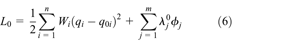
where n is the generalized coordinate number of the system; m is the number of system constraint equations;
When
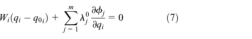
Its Newton–Raphson iteration formula is

where
The initial velocity of the model is analyzed, and the objective function

where
where


where

The above equation is a linear equation for
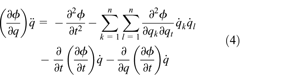
The analysis of the initial acceleration and the initial Laplace multiplier can be directly determined by the system dynamics equation and the second derivative of the system constraint equation. The system dynamics equation in matrix form is written into component form


where

The nonzero term in the upper expression has been decomposed; see equations (8) and (13). Therefore,
Motion simulation analysis
Designing motion trajectories using point drives
The 3D model of the 3-RPS parallel robot is built in ProE and imported into ADAMS/View environment for complete analysis, as shown in Figure 2. It consists of a moving platform, three branches, and a static platform. The movable platform is connected with the upper connecting rod of each branch chain through a spherical pair, the stationary platform is connected with the lower connecting rod of each branch chain through a rotating pair, and the upper and lower connecting rods of each branch chain are connected together through a moving pair. By driving the upper links, they change the contact length with the lower link, thus changing the position and posture of the moving platform in space. The moving platform of the parallel robot can realize the motion of two rotational degrees of freedom and one movement degree of freedom in space, totaling three degrees of freedom.15,16

3-RPS parallel robot kinematics model.
For parallel robots, kinematic analysis includes positive and inverse solutions to the kinematic equation. The positive solution problem refers to the length and speed of each known drive pair and solves the attitude and velocity of the active platform. The inverse solution problem refers to the length and speed of each drive pair that are known to solve the pose and velocity of the active platform. People put forward the requirements for the configuration of the end effector based on the robot’s operational tasks. It is necessary to find the joint coordinate values of each driving joint, so people are most concerned about the problem of solving inverse kinematics.17,18
In this article, the thread processing condition of parallel robot is selected as an example, and the complete dynamic analysis of the whole machine operation process is carried out. Because the inverse kinematics solution of parallel robot is simple, the solution of forward solution is complex. So the point drive at the end of the robot’s claw is used to force the robot to spiral motion. The point-driven position and time equation are established as follows

On this basis, the relative displacement curves between the upper and lower links of each branch chain were measured. These measured curves are the input conditions of each moving pair required for the parallel robot to perform the spiral motion. Then, by converting the measured curves into spline curves, the forward solution process of the parallel robot is realized by using it as the driving of moving pairs on each branch chain.
Producing measurements
After defining the point drive, you can get the movement of the hand. In the past, according to different mechanical structures of parallel robots, the matrix equation between the robot’s hand and the driving rod needs to be listed for calculation, and the real-time solution of a given trajectory requires a lot of mathematical calculation and computer language programming to complete, wasting time, and manpower. ADAMS can be used to easily solve the forward and inverse kinematics problems of the robot according to the given trajectory. The ADAMS software provides users with a variety of measurement functions to measure the relationship between displacement, velocity, and angle of different parts with time. It can also measure the relationship between force and moment of the constraint pair with time. It is possible to measure data in any coordinate direction. ADAMS software can measure data in any coordinate direction. In order to solve the kinematic relationship of the driving rod, the curve of the displacement and time variation of the driving rod can be measured in the simulation process, as shown in Figure 3(a)–(c). The figure is the curve of the displacement direction of the three driving rods obtained by 20 s and 200 steps simulation. After obtaining the measurement curve, the inverse solution of the parallel robot is basically completed.

Graph of resultant displacement: (a) between the upper and lower rods 1, (b) between the upper and lower rods 2, and (c) between the upper and lower rods 3.
Spline curve
In order to obtain specific data or require positive solutions, it is impossible to use the curve in the inverse solution. The post-simulation processing module can convert the data curve into a spline curve. ADAMS/View uses curve adaptation techniques to interpolate between data points, producing a continuous function. If the spline function has an independent variable, ADAMS/View uses a cubic polynomial method 3 to interpolate points from point to point. If the data of the spline function have two independent variables, ADAMS/View interpolates an independent variable between two points by using three times interpolation method, and then interpolates the second independent variable between curves by line method. The transformed spline curve can be a series of 2D (two-dimensional) or 3D discrete data points, or it can be a kind of labeled spline curve. It can add data points, modify data, add units, and so on. The graph of the three spline functions obtained is shown in Figure 4(a)–(c).
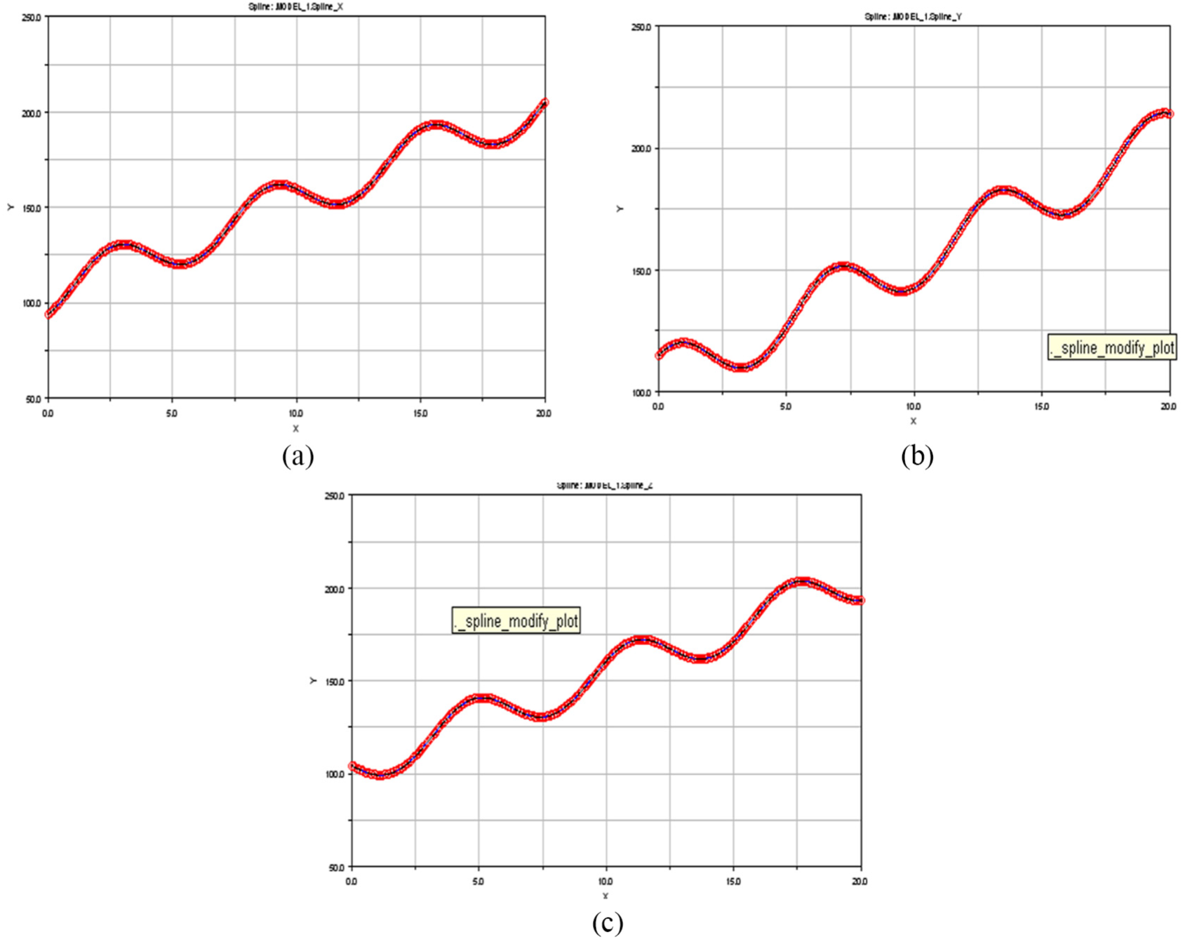
Spline curve: (a) between the upper and lower rods 1, (b) between the upper and lower rods 2, and (c) between the upper and lower rods 3.
Add driver
The inverse solution of the parallel robot has been obtained, the spline curve of the drive rod change is also obtained, and the known conditions of the positive solution have been obtained. According to the spline function provided by ADAMS, the discrete data points of the spline curve can be taken as the known conditions to generate the driving function of the driving rod. According to the function of spline function provided by ADAMS, the driver of robot can be added and the function of displacement changing with time can be added. Add constraint type drives to the three moving pairs respectively, and the functions of the drive displacement with time are as follows:

After the driver is added, the point drive is set to the inactive state, and the system model is simulated in 20 s and 200 steps, and the motion trajectory of the hand of the parallel robot can be obtained. Through the measurement function, the time-varying curve of the displacement, velocity, and acceleration of the hand can be obtained, and the motion trajectory of the hand can also be obtained. It can be seen from the simulation process that the trajectory of the robot’s hand coincides with the trajectory of the point drive, which proves that it is feasible to use the point drive, measurement, and spline function of the ADAMS software to solve the positive and inverse solutions of the parallel robot. The result is also correct.
Simulation analysis of rigid-flexible coupling dynamics of 3-RPS parallel robot
Dynamic equation
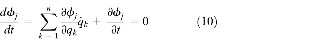
The ADAMS program uses the Lagrange multiplier method to establish the system motion equation 19
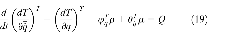
The corresponding fully constrained equation is shown in equation (20), and the incomplete constraint equation is shown in equation (21)


where T is the kinetic energy of the system, q is the generalized coordinate array of the system, Q is the generalized force array,
Write the system dynamics equation (19) as a general form


where q is a generalized coordinate array, u is a generalized velocity array,
For example, the state vector of the defined system is

Establishment of rigid-flexible coupled dynamics model of parallel robot
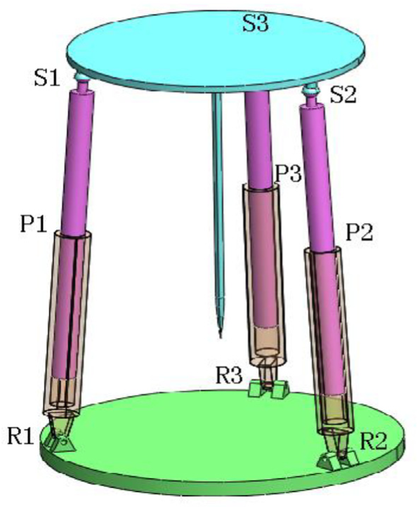
The 3D model of the 3-RPS parallel robot studied in this article is shown in Figure 5. It consists of a moving platform S1–S2–S3, three branches Ri-Pi-Si (i = 1, 2, 3), and a static platform R1–R2–R3.
Three-dimensional model of 3-RPS parallel robot.
In the finite element analysis software ANSYS, each branch link of the robot is flexible. Specify material properties and select cell type, cell properties, and mesh. According to the constraint relationship between each branch link in the ADAMS environment and other components, the outer joint point is defined, respectively, and the outer joint point enables the flexible body to establish a correct connection relationship with other components in the model. 20 The rigid-flexible coupling simulation flow of flexible body is generated by ANSYS software as shown in Figure 6.

Simulation procedure of rigid-flexible system.
After the outreach point is defined, the ANSYS loop command needs to be programmed. The beam4 unit is used to straighten the bearer area, and then the modal neutral file (.mnf) can be generated by using the interface between ADAMS and ANSYS. The .mnf generated in ANSYS is read in ADAMS/View, and the upper and lower links in the multi-rigid dynamic model are replaced with flexible bodies, that is, the rigid-flexible coupled dynamics model of 3-RPS parallel robot is generated.21–23
Displacement changes at the end of the claw
The establishment of the parallel robot dynamics model also requires to apply load to its body in accordance with actual working conditions. The load that is subjected to the threading process is the main force opposite to the direction of the tangential speed of the manipulator, and the size is 3000 N. Here, the three directions of force shown by equations (26) to (28) are applied to the end points of the claws of the robot using the function tool of ADAMS. Among them, MARKER_P is the end point of the robot hand, and MARKER_G is the ground point located at the center of the static platform. By decomposing the velocity of the measuring point at the end of the robot’s hand, the force acting on the robot in the global coordinate system can be obtained.


During the loading process, the robot will deform the connecting rods on each branch due to the load. The amount of deformation has a decisive influence on the machining accuracy of the parallel robot. 24 Through the simulation analysis of the fully rigid model and the rigid-flexible coupled model, the displacement curves of the end points of the two models of the robot in the vertical direction and their deformations can be obtained, as shown in Figure 7.

Displacement and error of measuring point along the vertical direction: (a) displacement curve and (b) error curve.
It can be seen from Figure 7(a) that there are some errors in the simulation curves of the two models under the same motion law and load conditions. The error is exactly the change of the displacement of the measuring point caused by the flexible connecting rod on each branch chain. And corresponding to different moments, the magnitude of the change has positive and negative points. Figure 7(b) is the error curve of the robot end measuring point under the simulation of two models. Combining the two graphs, we can get the following results:
From the displacement curve, it can be found that the displacement curve of the end of the robot’s hand measured by the rigid-flexible coupling system of the flexible body is more fluctuating than that of the multi-rigid system. However, the general trend can still be maintained near the displacement curve measured by the multi-rigid body system.
It can be seen from the error curve that the vibration is relatively intense during the initial operation phase of the robot. As the movement tends to be steady, the displacement error of the end of the hand in the vertical direction presents a periodic change, with a period of about 4.2 s.
During the entire working process of the robot, the maximum displacement error of the end of the hand in the vertical direction caused by the flexible link is about
The coordinate values of the end points at three different moments and their error values in the vertical direction are shown in Table 1.
Coordinate and error of measuring point along the vertical direction under three different times (unit: m).

Results and discussion
The rigid-flexible coupling dynamics simulation of the parallel robot system is carried out by using the flexible body link model of each branch chain, and the maximum stress of each link of the robot during the whole working process is obtained. The corresponding curve of the robot and its maximum stress point are shown in Figure 8.

Stress distribution and variation curve of connecting rods: (a) stress distribution of the connecting rod of the parallel robot and (b) stress curve of node 1732.
It can be seen from Figure 8(a) that the maximum stress value occurs at the root of the lower link of each branch chain. Corresponding to the configuration of the robot at 1.8 s, the maximum Von Mises stress is 202.64 MPa, which is smaller than the link material. The yield limit of carbon steel is 282 MPa, which shows that the lower link is safe. Figure 8(b) is a stress variation curve of the node 1732 at the maximum position of the lower link. It can be seen from the figure that during the whole operation of the parallel robot, the stress fluctuation range of the node is between 70 and 200 MPa, and the average stress value is about 135 MPa.
The added force is tangent to the trajectory of the movement, which ensures that the added force conforms to the actual working condition of the robot. Since the hydraulic cylinder rod has become flexible body, the stress changes of each link during the simulation can be calculated by ADAMS. After the simulation is completed, we measured the driving force and power consumption curve of motor 1 as shown in Figure 9.

Driving force and power consumption curve of motion 1: (a) driving force and (b) Power consumption.
From Figure 9, we can see that the maximum driving force of the motor 1 is 1300 N and the maximum power consumption is 22 W. It can be used as a reference for motor parameter selection.
In addition, the boundary conditions of the flexible body can be output after the simulation is completed, and the output file can be used as a load file for ANSYS analysis. Through ADAMS, file output menu can be completed.
Then, the stress and strain analysis of the connecting rod is carried out in ANSYS, and the generated load file is directly imported as the boundary condition. After appropriate processing, the solution can be obtained. The finite element analysis of key components is completed.
It is found that the current design strength is sufficient, but at the same time, it should be noted that with the change of the posture of the parallel robot, the stress direction of the lower link changes correspondingly, but the maximum stress position still occurs at the root of the lower link of each branch. Due to the high dynamic stress value of the lower link and the violent reciprocating oscillation, the stress at this position can be continuously accumulated, which will lead to fatigue damage of the link over time. Therefore, we need to carry out further fatigue tests and analysis on the root of the lower link, and check whether structural improvement is needed to improve the fatigue failure of the parts caused by this pulsating cyclic load.
Conclusion
In this study, the three software Pro/E, ADAMS, and ANSYS commonly used in engineering simulation are combined. The co-simulation method is used to model and simulate the rigid-flexible coupled dynamics model of 3-RPS parallel robot. Combining the advantages of three kinds of software, it overcomes the limitations of the software alone, which greatly improves the analysis efficiency and simulation accuracy. The conclusions obtained are as follows:
Through the rigid-flexible coupling dynamics simulation, the displacement curve and error curve of the end point of the 3-RPS parallel robot in the vertical direction are obtained. The displacement error shows a periodic change with a period of 4.2 s and a maximum error of
The position of the maximum stress of the lower link of the robot during the whole working process and the curve of the maximum stress point are obtained. The results show that the maximum Von Mises stress occurs at the root of the connecting rod with a value of 202.64 MPa, which is less than the yield strength of the material (282 MPa). However, due to the reciprocating oscillation of the stress, the fatigue failure of the structure will be caused.
The dynamic analysis of multi-body system is carried out by using rigid-flexible coupling method, which improves the accuracy of dynamic response analysis of parts under dynamic load, and can simulate the actual working condition of parallel robot more intuitively and accurately.
In the future, according to the actual task requirements, a 3-RPS parallel robot will be designed to obtain the motion parameter curves of each link at the end of the robot and the driving motor through experimental tests. In addition, the strain gauge will be attached to the maximum stress position to obtain the dynamic stress change curve in real time.
Footnotes
Handling Editor: Aki Mikkola
Declaration of conflicting interests
The author(s) declared no potential conflicts of interest with respect to the research, authorship, and/or publication of this article.
Funding
The author(s) disclosed receipt of the following financial support for the research, authorship, and/or publication of this article: This research is supported by the National Natural Science Foundation of China (Grant No. 51505470) and Youth Innovation Promotion Association, Chinese Academy of Sciences (CAS) (2018237), and Jiang Xinsong Innovation Fund.