
Abstract
As one of the dynamic disasters of deep mining, rockburst significantly affects the safety of underground environment especially at great depth. First, the elastic energy and dissipative energy are deduced to characterize rockburst process separately employing the theoretical analysis and test technique. Then, a series of split-Hopkinson pressure bar system tests are conducted. After calculation, the percentage of fractured dissipative energy occupied in total input dynamic energy is obtained. Subsequently, the dynamic mechanical parameters of rock specimens and dynamic impact factors are fitted. Finally, a three-dimensional model is developed using the mechanical property of the host rock, constitutive model, and in situ geostress. The contours of energy and the damage conditions of host rock are predicted, and the tendentiousness of rockburst is estimated.
Keywords
Introduction
With the rapid mining depth development, many adverse problems should be paid much more attention, such as rockburst, which is one of the most serious calamities on the stability of deep mines. Many scholars did a large number of researches on rockburst. Shan and Yan 1 discussed where rockbursts occurred, how they occurred, and how to reduce their effects during excavation of the deep tunnels in the Jinping II Hydropower Station. He and Dou 2 established a gradient principle of horizontal stress inducing rockburst in coal mining and proposed the criterion of horizontal stress inducing layer dislocation rockburst. Zhou et al. 3 analyzed the rockburst mechanisms induced by structural planes in deep tunnels and classified rockburst into three types. Dou et al. 4 studied the progress of monitoring, forecasting, and prevention of rockburst in underground coal mining in China. Hu et al. 5 used the experimental and numerical study on rockburst triggered by tangential weak cyclic dynamic disturbance under true triaxial conditions. Cai et al. made a quantitative analysis of seismic velocity tomography in rockburst hazard assessment. Many researchers presented that rockburst is an intensive energy releasing process. 6 Thus, more and more researchers started to investigate rockburst from the energy perspective. Zhou 7 adopted a strain energy density factor approach to study triaxial compressive behaviors of rock with mesoscopic heterogeneous behavior. Hamiel et al. 8 predicted the elastic strain energy of damaged solids with applications of non-linear deformation of crystalline rocks. Al-Dabbas and Al-Rousan 9 used a horizontal closed-loop system to extract energy from underground rock area. Li et al. 10 analyzed the strength, deformation, and strain energy of coarse crystal marble under uniaxial compression and pointed out that the more the stored elastic energy in the specimen, the stronger the fragmenting. Chen et al. 11 studied the rockburst intensity classification based on the radiated energy with damage intensity at Jinping II Hydropower Station. In order to obtain the massive amounts of analysis data, such as stress, strain, and energy, the different tests should be carried out. In this situation, various test methods emerged. He et al. 12 did an experimental investigation of bedding plane orientation on the rockburst behavior of sandstone. He et al. 13 adopted a novel experimental technique to simulate pillar burst in the laboratory. Moradian et al. 14 analyzed the acoustic emission signals parametric to detect cracking levels in brittle rocks. Gong et al. 15 adopted the true-triaxial experiment to study the fracture angle analysis of rockburst faulting planes.
However, rockburst is a serious disaster to an excavation or pillars that occurs in a sudden or violent manner and is associated with a seismic event, especially for the deep mining. They can cause serious casualties, mechanical damage, delay in projects, and economic loss. Moreover, the rockburst is a dynamic disaster, and the researches mentioned previously are based on the static tests, which are not suitable for the dynamic problem. Also, some achievements have been made in rockburst classification, stain energy, and laboratory tests, but there are still many uncertain problems to be solved because of the complex dynamic process of rockburst. Some scholars proposed some rockburst classification methods1–3 and used different laboratory facilities to study the stored strain energy.7–15 The works mentioned previously are based on the static tests, which are not suitable for the dynamic problem. In addition, most of the above methods usually analyze the storage energy without considering the energy distribution and the rock crushing energy consumption.
Numerical simulation has the advantages of high accuracy and less cost, which makes it become an important prediction method in the engineering. In addition, with the fast development of computer techniques, more and more scholars use finite difference software and finite element analysis software, such as FLAC3D and ANSYS, to solve dynamic problems.16–29
Therefore, the main idea of this article is fourfold: (1) by considering the energy mechanism of the rockburst, a calculation model of common mining area would be presented to analyze the rockburst energy including elastic strain and dissipative energy; (2) using the split-Hopkinson pressure bar (SHPB) testing system, a series of SHPB tests would be carried out, to obtain the percentage of the fractured dissipative energy occupied in total input dynamic energy; (3) meanwhile, to fit the dynamic mechanical parameters of rock specimens and dynamic impact factors (DIF) also with SHPB testing data; and (4) to predict the contours of energy and the damage conditions of host rock and estimate the tendentiousness of the rockburst by employing the numerical simulation method.
Theoretical analysis and test evaluation of rockburst energy
Rockburst energy theoretical analysis
The rockburst is defined as damage to an excavation or pillars that occurs in a sudden or violent manner and is associated with a seismic event. 30 The rockburst during deep mining shows the highest frequency of occurrence of disaster. They can cause serious casualties, mechanical damage, delay in projects, and economic loss. In the deep underground metal mining, the room and pillar mining method is a common mining method. In this method, the pillars are retained to support the roof, which are the hardcore of the stability of the mine. The general mining method and simplified mechanical model are shown in Figure 1. The common mining areas are composed of covered rock, cutting surface tunnel, safety pillar, pillar, transportation tunnel, and base rock (Figure 1).

Room and pillar mining method: (a) general mining method, (b) simplified structure model, and (c) simplified mechanical model.
A large number of studies have established that the rockburst in the pillar is a sudden dynamic instability phenomenon with host rock fracture and flying of stones (Figure 1(a)). However, the top covered host rock was not damaged; it only participated in energy release. 31 Meanwhile, based on the mechanical theory, the top covered host rock can be simplified as rock beam. Thus, the rock beam with pillar model was indicated in Figure 1(b).
For the model in Figure 1(c), the pillar can be considered as concentrated force F, the weight of rock beam and the covered host rock can be equally as the uniformly distributed load q, and the deformation of the pillar is much larger than the displacement of unquarried ore body (or safety pillar), in that, the unquarried ore body can be regarded as the incompressible rigid body, and the beam was fixed and embedded in it. Hence, the flexural rigidity of the beam EI remains in elastic state during the pillar destruction process

where I is the stiffness coefficient, and
Again, Karcinovic 32 presented the relationship between the stress and strain of the pillar, as shown in equation (2)

where
Thus, for the midpoint C, the acting force of pillar of the relationship between loading and displacement of the pillar is

where
Finally, equation (3) with the equivalent stiffness of the pillar
Relationship between loading and displacement of pillar.
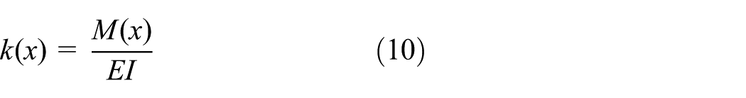
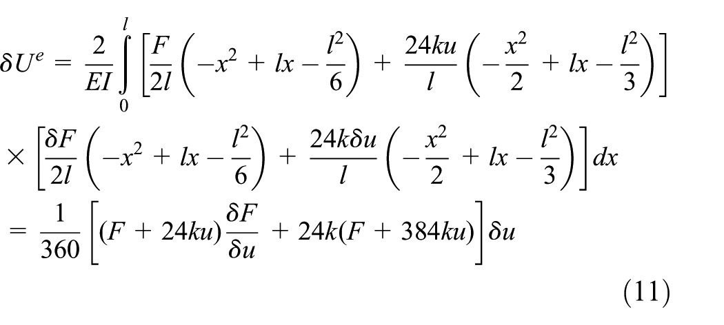
Based on the rock mechanics,

According to the theoretical mechanics, the relationship between the deflection u at the midpoint C in the beam and the uniformly distributed load q and concentrated force F is

where l is half length of the rock beam.
Before the occurrence of the rockburst, the rock beam is under quasi-static condition, and there is no influence of kinetic energy. Thus, the release of elastic deformation energy


where
Substituting equations (5) and (7)–(9) into equation (6), and assuming

Substituting equation (3) into equation (12) and dividing

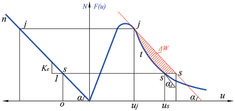
The MATLAB software is used to draw the curve of equation (13), which is shown in Figure 3 cure I


Process of elastic potential energy and the release of energy.
Also, the MATLAB software is used to draw the curve of equation (14), which is shown in Figure 3 curve II.
As shown in Figure 3, the curve I (red) is the curve of release of energy, the curve II (green) is the fitting line of the elastic potential energy, and the curve (blue) is the mirror curve of the curve II. Obviously, the shadow area (common region of the curve I and the blue curve) is the residual energy for the kinetic energy of the rockburst
SHPB tests
In this study, we carried out the SHPB test in order to obtain the energy distribution and dynamic properties of host rock.
The sketch and typical SHPB test system (University of Science and Technology Beijing lab, Beijing, China) comprises three systems: the power system, the work system, and the monitoring system. The power system contains pressure chamber. The work system contains the impact bar, incidence bar, and transmission bar. The monitoring system contains the laser velocity measurement, the signal-acquiring device, and the high-speed camera. The diagram and physical photo of the SHPB test system are shown in Figure 4(a) and (b), respectively.

Split-Hopkinson pressure bar test: (a) sketch of SHPB test system, (b) SHPB test system in lab, (c) rock samples
The rock samples are shown in Figure 4(c). In the tested procedure, granite and iron ore were drilled from 1000 m depth underground (Anshan, Liaoning province, China). After incision, rubdown and number, the rock samples were set between the incidence bar and transmission bar and coupled with the mineral butter well. Next, the dynamic strain acquisition system was pasted on the incident bar and transmission bar for monitoring the strains during the test.
After the preparatory work, the SHPB test could be carried out as below. First, the gas was stored and increased by the pressurization system in the air shot to apply the kinetic energy of the impact bar, and the laser velocity measuring instrument can indicate the velocity of impact bar, which could be used for calculating the strain rate of test. Second, the impact bar impacted the incident bar to give the energy to incident bar working on the rock sample, so that the rock samples were damaged with different impact velocities (different strain rates). Finally, after fracturing the rock sample, the residual energy is delivered to the transmission bar and then it would be absorbed by the damper at the end of SHPB system. During the whole process, the incidence energy, the reflection energy, and the transmission energy could be monitored by the dynamic strain acquisition system and shown on the computer (Figure 4(b)).
After 32 SHPB tests, the typical samples were impacted as shown in Figure 4(d). Based on the different lumpiness of rock after different strain rate impact, the damage degrees were divided into four grades: partial failure (such as specimen 2-1, 2-2, 2-3, and 2-8 in Figure 4(d)), large block fracture (such as specimen 2-4, 2-5, 2-9, and 2-10 in Figure 4(d)), small block fracture (such as specimen 2-7, 2-11, 2-12, and 2-13 in Figure 4(d)), and powdery fracture (such as specimen 2-6, 2-14, and 2-15 in Figure 4(d)). Through the test statistics, the average strain rate for forming partial failure is 124 s−1, for the large block fracture is 151 s−1, for the small block fracture is 203 s−1, and for the powdery fracture is 260 s−1.
Figure 5 shows the particular curves of incident energy and transmission energy, and it is shown that the fractured dissipative energy can be analyzed considering the incident energy and the transmission energy in the incident bar and the transmission bar, respectively. Using the MATLAB one-dimensional (1D) wavelet transform module to deal with above energy curves, after the noise removal processing, the difference value between the incident energy and the transmission energy is the consumed energy by rock failure. It means that the difference energy is the fractured dissipative energy under dynamic loading. Deducting this rock failure consumed energy from the total stored energy; the residual energy is source energy of rock blocks shot off during the rockburst; therefore, the reference point of the rockburst break intensity was confirmed.

The curves of incident energy and transmission energy.
Rockburst prediction based on finite difference computational model
In the deep underground, the host rock puts up the special mechanical behavior and good energy storage characteristic, the greater cover depth realizes the higher storage energy, under this higher storage energy, the excavation must have an effect on stability of host rock, even the rockburst. So, in order to make sure the safety mining, rockburst tendentiousness prediction is necessary.
Engineering background
In this study, an underground mining was chosen as the case study of rockburst (Gongchang Ridge, Anshan, Liaoning Province, China). In order to reduce the burden of simulation, nine mining stope rooms with its host rock were cut out from the 1000-m-deep underground. The lithology of host rock mainly is the iron ore, and the cover rocks are the conglomerate and granite.
Therefore, a three-dimensional (3D) finite difference model was developed in FLAC3D (Itasca, Minnesota, USA 33 ) software with the same lithology and dimensions of real mining process. There is also a 30° dip angle between the ore body and horizontal plane. The geometrical dimensions of whole model are: 240 m length (X direction), 160 m width, and 100 m height. Nine mining stope rooms were in the middle of model and were divided by the safety pillars. The dimensions of each stope room are as follows: length 40 m (X direction), width 20 m, and height 10 m. After mining, 15 pillars are retained to support the roof and keep the stability of every stope room. Every pillar is a cuboid with 3 m × 2 m and ore body thickness height.
The finite difference mesh consists of 252,601 nodes and 383,410 elements. The element numbers and element types of 3D finite difference model are shown in Table 1. The simulation model and its location are shown in Figure 6.
Element number and element type of 3D finite difference model.


3D finite difference model in FLAC3D: (a) location of simulation 3D finite difference model, (b) 3D finite difference model with host rock, (c) 3D finite difference mining area model before exploitation, and (d) 3D finite difference mining area model after exploitation.
Simulation constitutive models and parameters
The model was simplified along with actual layers, in the 1000 m depth, and the host rock is iron ore. In the elastic stage, the constitutive models were elastic model for the rockburst simulation. The properties of the elastic model (bulk modulus, shear modulus, and density) are shown in Table 2

where
Calculation parameters in numerical simulation.

After the elastic stage, the materials will be presented as plasticity. In this simulation, the Mohr-Coulomb model was chosen as plasticity constitutive model according to the characteristics of host rock. It is easy to know that

And the Mohr-Coulomb criterion can be represented in the plane

A tension failure criterion of

where

So the potential function is described by means of two functions, and

where

Also, the dynamic simulation parameters of host rock were obtained from Table 2.
Boundary condition and in situ geostresses
For the boundary condition, the four lateral surfaces on the model were set as normal fixed boundary. For the top surface, it was loading boundary to indicate the weight of cover rock. And for the bottom surface, it was fixed in three directions. The whole model was accepted the in situ geostress. The geostress was broken up into three directions alongside the model X, Y, and Z axes using stress projection method; therefore, the three-axis geostress components following cover depth were obtained, and the numerical model would accept these gradient form components following cover depth to simulate the in situ geostress boundary conditions. The sketch map of the boundary condition is shown in Figure 7.
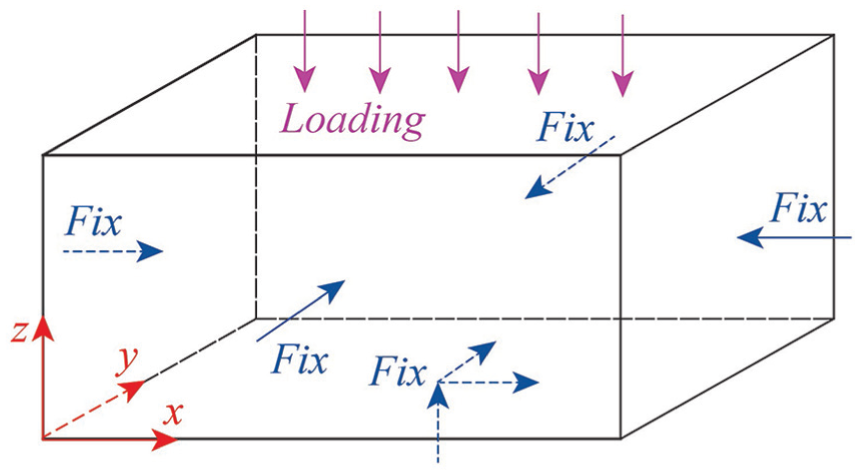
Boundary condition of simulation model.
Energy analysis
Rockburst is one of the significance disasters in the deep underground engineering; after excavation in the large energy storage host rock, it is an intensive and instantaneous dynamic process with massive energy; the essence of rockburst is the energy storage and energy release, so the energy analysis is sally port of the rockburst analysis.
To analyze the energy distribution and aggregation degree in the host rock during the mining process, the stored strain energy in FLAC3D simulation is

where
Equation (22) could be programmed into FLAC3D as an extra variable based on calling the simulated stress and strain values of every element; therefore, the contour of the energy could be predicted.
Results and discussion
SHPB test
After summarizing the test result of fractured dissipative energy by considering the proportion difference between the incident energy curve and transmission energy curve, the fractured dissipative energy occupied in the total input dynamic energy can be calculated (Figure 8(a)).

Fitted results of test data: (a) fitted line of fractured dissipative energy occupied in the total input dynamic energy, (b) fitted line of dynamic compressive strength under different strain rate, and (c) fitted line of dynamic impact factor under different strain rate.
Calculated data in Figure 8(a) show that the higher fractured dissipative energy occurred in the higher strain rate impacted rock materials; thus, the equation of fractured dissipative energy occupied in the total input dynamic energy can be fitted as

where
By analyzing the incident strain and transmission strain, the dynamic compressive characteristics can be obtained from the above tests, as shown in Figure 8(b) and fitted in equation (24).

To explain the dynamic hardening characteristic of rock material, also for numerical simulation, the DIF can be obtained from lab tests, which can be expressed as

Analyzing the test data, which is shown in Figure 8(c), the DIF equation can be fitted as

Based on the SHPB test, the stored strain energy by rejecting the fractured dissipative energy is

In situ geostress
Geostress is an important effect factor on the rockburst, and it is gradually forms in a long geological history, as a result of gravitational field and geotectonic stress.
In this study, in situ geostress monitoring data were measured by taking the hydro-fracturing method. The results are shown in Figure 9. The maximum principal in situ was horizontal stress. The maximum value is 1.6 times of minimum value in horizontal direction. And the maximum horizontal stress is two times of vertical stress.

The regression curve for the relation between σ1, σ2, σ3 and depth.
Rockburst prediction
Programming equation (15) into FLAC3D by reading the stresses, strain and strain rate of every element, thus, an extra defined variable, which is indicated as the stored strain energy by rejecting the fractured dissipative energy, could be simulated.
After the simulation, the whole and partial model energy contours (rejected the fractured dissipative energy) could be predicted (Figure 10). The simulation results show that the strain energy is a gradual increase with the depth in the deep underground. And there is an obvious higher strain energy accumulation area around the stopes, and this high energy environment is the disaster factor of rockburst.

The energy contour of whole model.
According to the different energies (rejecting the fractured dissipative energy), the rockburst can be divided into four grades


To selectively analyze the energy accumulation condition of pillars, partial model energy contours were enlarged from the whole energy contour. The highest energy accumulation area occurred in two sides of pillars facing the excavation area (Figure 10). In this simulation, a total of 90 pillars were analyzed. The value of strain energy in pillars is from ∼3.6 × 10⁴ J/m3 to 1.2 × 10⁵ J/m3. In addition, the energy of 45 pillars, particularly the two sides, was larger than 4 × 10⁴ J/m3, based on the grading standard (equation (28b)).
There was a medium rockburst risk in these pillars. Even if six of them were in the supernatant stopes, the energy was larger than 1.0 × 10⁵ J/m3. Therefore, adopting the grade criterion of rockburst in equation (28c), it is easy to estimate that there is the strong rockburst risk in these six pillars. Thus, the dangerous area is the two sides of the pillars, especially, the higher energy pillars, which should pay more attention to the rockburst and tendentiousness of rock shot off.
Conclusion
In this study, by considering elastic energy and fractured dissipative energy, the percentage of the fractured dissipative energy occupied in total input dynamic energy was obtained after carrying out the SHPB system tests, the testing result shows that the percentage is about 15%, and there is a certain rising trend with increasing of impact strain rate. Also, the dynamic mechanical parameters of rock specimens and DIF were fitted from the SHPB test data. Finally, based on the in situ geostress monitoring data, the strain energy expression was programmed into the finite difference software FLAC3D. After simulation, the contours of energy, the damage conditions of the host rock, and the tendentiousness of rockburst were predicted. The contrasting results show that the energy of 45 pillars, particularly the two sides, was larger than 4 × 10⁴ J/m3, and even for six of them, the energy was larger than 1.0×10⁵ J/m3. This also means that there will be medium rockburst risk, even strong rockburst risk, and the dangerous area is the two sides of the pillars, for which more attention should be paid to the rockburst and tendentiousness of rock shot off.
Footnotes
Handling Editor: Farzad Ebrahimi
Authors’ note
Liping Wang and Jianghui Dong are also affiliated with Department of Hand Surgery, Ningbo No. 6 Hospital, Ningbo, China.
Declaration of conflicting interests
The author(s) declared no potential conflicts of interest with respect to the research, authorship, and/or publication of this article.
Funding
The author(s) disclosed receipt of the following financial support for the research, authorship, and/or publication of this article: This work was supported by National Natural Science Foundation of China (Nos 51704014 and 51674013).