
Abstract
The influence of tunnel excavation on adjacent buildings or structures must be considered when new tunnels pass through existing buildings or structures. In this article, based on the project of the Aotidong-Aotizhongxin section of Shenyang Metro Line 9 passing through the existing Aotizhongxin station of Line 2, the numerical simulation was employed to research the settlement laws of the existing station’s baseplate by four methods, namely the full-face excavation method, the benching tunneling method, the side heading method, and the center diaphragm (CD) method. Based on the results of numerical calculations, in order to ensure the safe and normal operation of existing station, it was recommended to use the CD method to construct the new tunnels. At the same time, the advanced deep hole grouting reinforcement technology and jack-up technology should be adopted in the process to reduce settlement of the station’s baseplate. The CD method proved applicability in the project by comparing the field-monitoring data with the numerical calculation results. The results can provide reference for the design and construction of similar projects in the future.
Introduction
It is inevitable that the metro tunnel construction will cause the vibration of surrounding existing structures, which will further lead to the settlement of the existing structures.1–7 When the settlement is large in scale, it will influence the normal function of existing structures or even damage them. Therefore, appropriate construction methods adopted and corresponding protective measures taken during tunnel construction have great significance for reducing the impact of tunnel construction on surrounding existing structures as well as for the safety of newly built tunnel.8–12
A significant number of researches have been performed to study the settlement of the existing structures caused by the excavation of newly built tunnel. Mroueh and Shahrour 13 used an elastoplastic three-dimensional (3D) finite element modeling to analyze the interaction between tunneling and a group of piles and revealed a positive group effect with a high reduction of the internal forces in rear piles. Liu et al. 14 investigated the influence of different construction schemes on the tunnel heave and showed the influence on the tunnel heave from various factors, such as the ground reinforcement depth, excavation sequence and the skew angle between new tunnel and existing tunnels. Ma et al. 15 used a series of 3D centrifuge model to study the effects of twin tunnel construction on an existing single pile in dry sand and found that the pile settlement induced by the excavation of the twin tunnels was closely related to the depth of each tunnel relative to the pile. Zheng et al. 16 developed a simplified semi-empirical method of assessing the deformation of tunnels laterally adjacent to excavations and demonstrated the accuracy of the proposed model. Zhang et al. 17 proposed a two-stage analysis method to study the behavior of pile groups with rigid elevated caps subjected to tunneling-induced ground movements. This method is validated by comparing the results with those from a general pile analysis program (GEPAN), centrifuge test data, and field measured data. Chen et al. 18 presented a novel construction method for excavations crossing above underlying tunnels, referred to as the divided alternate excavation method (DAEM) to control the existing tunnel deformation induced by an adjacent excavation, and field data revealed that the novel method has advantages in controlling deformation of the underlying metro tunnels. Zhang and Huang 19 got multiline propulsion main parameters, including the earth pressure for cutting open, and the synchronized grouting through the deformation analyses of existing subway tunnels induced by an earth pressure balance (EPB) shield during the process of above-overlapped and down-overlapped crossing tunnels with oblique angles. Mostafa et al. 20 analyzed the selection of excavation method, excavation sequence, and optimum trailing distance between different excavation stages in soft ground urban tunneling. And their research gave some references for other similar projects. Fang et al. 21 analyzed the settlement of the existing tunnel and the ground surface while the new twin tunnels were excavated by the shallow tunneling method and found that the settlement profile of the existing structure displays a “w” shape, while the ground surface settlement profile displays a “u” shape.
The running tunnels between Aotidong Station and Aotizhongxin Station of Shenyang Metro Line 9 located in Liaoning Province of China cross the existing Aotizhongxin Station of Metro Line 2 from east to west. This article simulated the construction process of tunnels newly built right beneath large-span metro station through four construction methods, including full-face excavation method, benching tunneling method, side heading method, and center diaphragm (CD) method and analyzed the baseplate settlement rules of existing station under the four methods, respectively. After comparing the calculation results of the four construction methods, CD method was suggested for tunnel construction. Through the comparison with monitoring data, it was found that the numerical simulation results agree well with the monitoring data, indicating that CD method has a good control over the settlement of existing station’s baseplate. The research results can provide reference for the design and construction of other similar projects.
Project description
Shenyang Metro Line 9 is an important line in Shenyang metro network which has 23 stations and covers a total length of 28.9 km. It starts at Shenyang Jianzhu University Station and arrives at Greely Lake Street Station after passing 12 stations from east to west, including Aotidong Station and Aotizhongxin Station and then goes through eight stations from south to north and finally ends at Nujiang Park, displaying an “L” shape. The running tunnels between Aotidong Station and Aotizhongxin Station stretches along the Hunnan Fourth Road direction and crosses the existing Aotizhongxin Station of Metro Line 2 from east to west.
The aforementioned running tunnels start at DK23+113.690 and end at DK24+233.956. The left tunnel is 1130.9 m in length and the right one is 1120.3 m. The running tunnels were excavated by mining method and have flat roof and upright wall for the section beneath the existing station. The distance between the newly built tunnels and the existing station is 0 m in the vertical direction. The center line of the running tunnels of Metro Line 9 intersects with Metro Line 2 at the existing Aotizhongxin Station with an angle of 81°. The actual overlapping length of the newly built running tunnels and the existing station is 21 m approximately. The two running tunnels are 7.35 m in width and 7.78 m in height. The distance between the center lines of right and left tunnels is 16.7 m. The Aotizhongxin Station of Metro Line 2 is an island platform with a two-layer three-span box structure whose section is 20.5 m in width and 13.06 m in height. The roof plate, middle plate, baseplate, and side plate of the station have a thickness of 800, 400, 900, and 600 mm, respectively. The station’s beam column is a rectangular pillar with a 600 mm × 1100 mm sectional dimension. The major structure of the station is 163.8 m in total length. The effective platform width is 12 m and the standard section width is 20.5 m. The structure’s roof plate is covered with a 3.5 m layer of soil and the burial depth of baseplate is about 16.9 m. According to the geological exploration data, the station and the tunnels are covered with Q4ml (quaternary holocene man-filling layer), Q42al (quaternary holocene alluvium layer), and Q41al + pl (quaternary holocene alluvium and proluvial layer) from up to down. The burial depth of groundwater level at the construction site is 10.7–13.8 m. In order to ensure the stability of excavation face, the light well point dewatering method was adopted to reduce the groundwater level below the bottom of the newly built tunnels before excavation.
Figures 1 and 2 show the plan and sectional view of Metro Line 9 for crossing the existing Aotizhongxin Station of Metro Line 2, respectively. The distribution of soil layer within 30 m below the ground surface is shown in Figure 3.

The plan view of Metro Line 9 for crossing the Aotizhongxin Station of Metro Line 2.
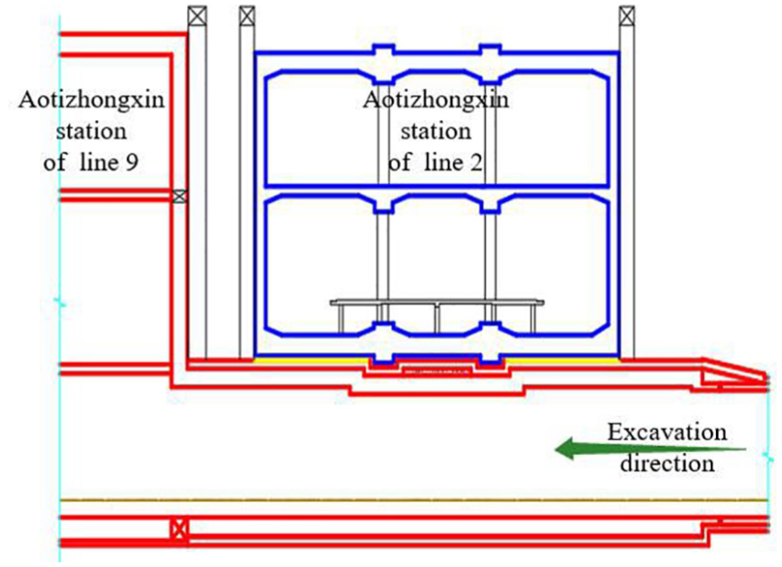
The sectional view of Metro Line 9 for crossing the Aotizhongxin Station of Metro Line 2.

The distribution of soil layer within 30 m below the ground surface.
Optimization of construction method
According to the project profile mentioned in section “Project description,” special attention should be paid to the impacts the tunnels excavation project exerts on the existing Aotizhongxin Station of Metro Line 2. Thus, based on numerical simulation method, this article, using Midas/GTS NX geotechnical finite element software, analyzes the laws in the influences of newly built tunnels on the baseplate settlement of existing station caused by full-face excavation method, benching tunneling method, side heading method, and CD method.
Geologic model
It can be known from the geological conditions that the soil mass at the construction site is composed of homogeneous stratified layers, which from up to down are 0.8 m miscellaneous fill layer, 1.6 m silty clay layer, and 27.6 m gravelly sand layer, respectively. The 3D geologic model built based on the aforementioned stratum situation is shown in Figure 4, where the negative direction of Axis X is the tunneling direction of Metro Line 9, the positive direction of Axis Y is the north direction, and the positive direction of Axis Z is the upward direction.

Three-dimensional finite element simulation model.
As the tunnel excavation will definitely result in the vibration of surrounding rocks in a certain range,22–24 thus, to reduce the influence of boundary constraints, the distance between the left or right boundary of model and the center line of tunnel should be three times larger than the running tunnel width, that is, over 22.05 m. Therefore, the length of Axis Y of the model is set to 70 m. The X, Y, and Z of model are 40, 70, and 30 m in length, respectively. Tetrahedron-hybrid grids are used to divide the established geological model into 2388 elements, including 2316 joints. Specifically, the soil mass is simulated through 3D solid elements, and the constitutive model is simulated through Mohr–Coulomb Model;25–27 the roof plate, middle plate, baseplate, and side plate of the existing station are simulated through two-dimensional (2D) plate elements, and the constitutive model is elastic; the lining supports (shotcrete) of the newly built tunnels are simulated through plate elements with a width of 350 mm, and the constitutive model is elastic; the steel supports are simulated through one-dimensional (1D) linear elements, and the constitutive model is elastic. Since the groundwater level has been reduced below the bottom of the newly built tunnels before construction, the influence of groundwater is not considered in the simulation.
The four vertical faces and the bottom boundary faces of the established model are all constrained by normal displacement. The ground is a free-boundary surface.
According to the exploration data of the running tunnels (Aotidong Station∼Aotizhongxin Station of Metro Line 9) and the design information of the existing Aotizhongxin Station of Metro Line 2, the physical and mechanical parameters of soil layers are given in Table 1, and the attributes and parameters of components of tunnels and existing station are listed in Table 2.
Physical and mechanical parameters of soil layers.

Attributes and parameters of components of tunnels and existing station.

B: breadth; H: height; tf: thickness of the flange for H type steel; tw: thickness of the web for H type steel; T: thickness of the primary lining.
Construction methods
Aimed at analyzing the influence of newly built tunnels on the baseplate settlement of existing metro station through numerical simulation (Midas/GTS NX), this article uses full-face excavation method, benching tunneling method, side heading method, and CD method to simulate the construction of newly built tunnels and analyzes the laws in the baseplate settlement of existing station caused by the four tunnel excavation methods.
The processes of the four tunnel construction methods are shown in Figure 5. The details of the excavating steps are given below.
Full-face excavation method: excavate Soil Mass ➀ (green region) with 0.5 m forward each time; the contour surfaces exposed after each excavation step are applied with steel supports and shotcrete; the next excavation is performed during the supporting; excavate the left tunnel when the right tunnel has been excavated 15 m.
Benching tunneling method: excavate Soil Mass ➀ (green region) at the top, and then excavate Soil Mass ➁ (yellow region) at the bottom; the yellow region is excavated 12 steps later after the green region; each excavation makes 0.5 m forward; the contour surfaces exposed after each excavation step are applied with steel supports and shotcrete during the next excavation; excavate the left tunnel when the right tunnel has been excavated 15 m.
Side heading method: excavate Soil Mass ➀ at the left side (green region) first and then excavate Soil Mass ➁ at the right side (yellow region); the soil in the yellow region is excavated 12 steps later after that in the green region; each excavation makes 0.5 m forward; the contour surfaces exposed after each excavation step are applied with steel supports and shotcrete during the next excavation; excavate the left tunnel when the right tunnel has been excavated 15 m.
CD method: the Soil Mass ➀ (green region) is excavated first, followed by Soil Mass ➁ (yellow region), Soil Mass ➂ (purple region), and Soil Mass ➃ (blue region) successively; each region is excavated 12 steps earlier before the next region; each excavation makes 0.5 m forward; the contour surfaces exposed after each excavation step are applied with steel supports and shotcrete during the next excavation; excavate the left tunnel when the right tunnel has been excavated 15 m.

Processes of four tunnel construction methods: (a) full-face excavation, (b) benching tunneling, (c) side heading method, and (d) CD.
Analysis on calculated results
Analysis on the overall settlement of station
The diagrams for the vertical settlement of existing station caused by four tunnel excavation methods are shown in Figure 6. The maximum vertical settlements of existing station caused by the four methods reach 4.49, 6.83, 2.49, and 2.05 mm, respectively.

Station settlement diagrams of four tunnel construction methods: (a) full-face excavation method, (b) benching tunneling method, (c) side heading method, and (d) CD method.
The maximum vertical settlement caused by full-face excavation method appears at the station’s baseplate where the center line of right tunnel is beneath it. The baseplates above the left tunnel and the right tunnel have both subsided, resulting in a settlement of about 3.50–4.40 mm. The settlements at the north and south ends of the station are relatively small. The settlements at the junctions of baseplate and side plates are larger than those at the middle of the baseplate. The maximum settlement caused by benching tunneling method is 6.83 mm and appears at the center line of right tunnel. The baseplates above the left tunnel and the right tunnel have both subsided, with larger settlements at the middle and smaller settlements at the junctions of baseplate and side plates. The settlements at the north and south ends of station are relatively small. The maximum settlement of station’s baseplate caused by side heading method appears at the middle of the two tunnels; the settlements near the side plates of station are large and reach 1.97–2.28 mm and 1.68–2.21 mm at the west side plate and east side plate, respectively. For CD method, the maximum settlement is 2.05 mm and appears at the corresponding place beneath which the soil of right tunnel is excavated first; the baseplate settlements above the right tunnel are larger than those above the left tunnel, and they respectively range within 1.78–2.00 mm and 1.10–1.50 mm; besides, the south end of station has larger settlements than the north end.
According to the above analyses, the settlement caused by benching tunneling method (6.83 mm) is the largest, followed by full-face excavation method (4.49 mm), side heading method (2.49 mm), and CD method (2.05 mm). The reason why benching tunneling method has larger settlements than full-face excavation method lies in that the tunnels in this study is designed with a structure of flat roof and upright wall and the excavation face of benching tunneling method as well as the steel frame is rectangular, which makes the surrounding rock unable to give full play to its self-supporting capacity. Therefore, benching tunneling method is unsuitable for the tunnels with a structure of flat roof and straight walls which is excavated right beneath an existing station. The maximum settlement caused by full-face excavation method is much larger than those caused by side heading method and CD method, and thus it is not recommended either. Comparatively speaking, side heading method and CD method both have a good control over the baseplate settlement of existing station.
Analysis on the vertical settlement of station’s baseplate
For more details on the laws in the settlement of existing station along the vertical direction (the excavation direction of newly built tunnels), the baseplate settlements corresponding to the joints on the left tunnel and right tunnel are analyzed. The positions of the joints are shown in Figure 7.

Layout of joints on the baseplate of station.
Figures 8 and 9 show the baseplate settlements corresponding to the right tunnel and the left tunnel, respectively. The intersection of the center lines of station and tunnels is regarded as the origin of coordinates. The excavation direction of tunnel is the negative direction.

Settlement of station’s baseplate corresponding to the right tunnel.

Settlement of station’s baseplate corresponding to the left tunnel.
As shown in Figures 8 and 9, the settlements of baseplate caused by side heading method and CD method are relatively small, followed by full-face excavation method and benching tunneling method successively. For full-face excavation method, the settlements of station’s baseplate corresponding to the center lines of right tunnel and left tunnel are about 3.5–4.5 mm and 3.5–4.2 mm, respectively. For benching method, the settlements corresponding to the center lines of right tunnel and left tunnel are 5.0–6.8 mm and 5.0–6.2 mm, respectively. Similar to full-face excavation method, the settlements at both ends are larger than those at the middle. For side heading method and CD method, the settlements corresponding to the center lines of right tunnel and left tunnel are small and range within 1.8–2.2 mm and 0.7–2.2 mm, respectively. Besides, the settlement profiles are relatively flat.
After comparing the settlement profiles of baseplate corresponding to both tunnels, it can be known that the settlement caused by benching tunneling method is the largest. Besides, the settlement caused by full-face excavation method is much larger than those caused by side heading method and CD method. The settlement profiles of side heading method and CD method corresponding to the right tunnel are flat, indicating a small difference in settlements for measuring points. Comparatively, the settlements above the center line of right and left tunnel caused by CD method are smaller than those caused by side heading method.
Analysis on the lateral settlement of station’s baseplate
To study the law in the lateral settlement (along the connecting line of beam-column joints) of existing station’s baseplate, the settlements of joints on the five characteristic lines shown in Figure 10 are analyzed. Characteristic Lines 1 and 5 are the center lines of side spans of the existing station and also the lanes of Metro Line 2. Characteristic Line 3 is the center line of the middle span of the existing station. Characteristic Lines 2 and 4 are the connecting lines of beam-column joints.

Layout of lateral joints on the baseplate of station.
Figure 11 shows the distribution of lateral baseplate settlement caused by full-face excavation method. It can be known from Figures 10 and 11 that the excavation of left tunnel and right tunnel increases the settlements of station’s baseplate above them. This influence become smaller when the distance between joints and tunnels gets larger, or in other words, the settlement reduces with the increase of distance. Consequently, the vertical settlement of baseplate displays a “W” shape. The maximum settlement is 4.64 mm, approximately. As shown in Figure 11, the settlement curves of characteristic Lines 2, 3, and 4 almost overlap, indicating that the lateral settlements of baseplate at the middle part are quite close. The settlements of characteristic Lines 1 and 5 differ slightly with (are about 1.0 mm larger than) those of characteristic Lines 2, 3, and 4 at the north and south ends of station. In conclusion, the overall settlements of the five characteristic lines are large, yet the differences among them are small.

Distribution of lateral baseplate settlement caused by full-face excavation method.
Figure 12 shows the distribution of the lateral settlement of station’s baseplate caused by benching tunneling method. Similar to full-face excavation method, the vertical settlement profile displays a “W” shape as well. The settlements over the right tunnel are the largest while those over the left tunnel are relatively small, leaving two settlement grooves with different depths. As shown in Figure 12, the maximum settlement caused by benching tunneling method is about 6.83 mm, which is much larger than the 4.64 mm caused by full-face excavation method. However, for the north and south ends of the station, benching tunneling method and full-face excavation method are close in settlements. In summary, benching tunneling method is poor in controlling the baseplate settlement of station with new tunnels excavated beneath it.

Distribution of lateral baseplate settlement caused by benching tunneling method.
Figure 13 shows the distribution of lateral settlement of station’s baseplate caused by side heading method. It can be known from Figure 13 that the excavation of left tunnel and right tunnel as well as the superimposed effect has increased the baseplate settlement above the center line of the two tunnels to its maximum. Thus, the settlement curves show a “V” shape. The maximum settlements of the five characteristic lines which are about 2.21–2.49 mm appear near the center line the two tunnels, generating a wide shallow settlement grove. Side heading method has a good control over the settlement of baseplate. The settlement caused by this method ranges from 0.75 to 2.49 mm.
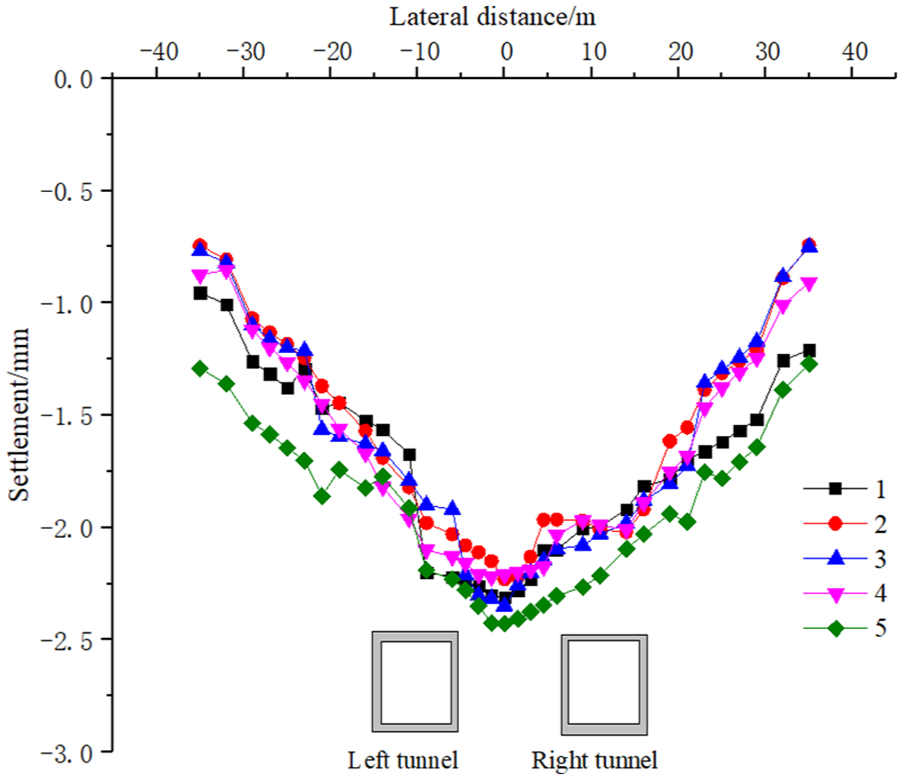
Distribution of lateral baseplate settlement caused by side heading method.
The distribution of lateral baseplate settlement of station caused by CD method is shown in Figure 14, from which we know that the settlement profile displays a “W” shape, and the overall settlement is small. The settlements of baseplate above the right tunnel and the left tunnel differ significantly. The maximum settlement corresponding to the early-excavated right tunnel is about 1.84–2.13 mm, while that corresponding to the left one is only 0.85–1.33 mm, indicating that CD method can effectively reduce the baseplate settlement caused by the excavation of tunnels, especially the left one.

Distribution of lateral baseplate settlement caused by CD method.
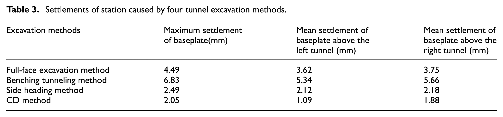
Settlements under four tunnel excavation methods
The baseplate settlements of existing station caused by four different tunnel excavation methods are compared, and the results are given in Table 3. The average settlement of baseplate corresponding to the left tunnel or the right tunnel can be calculated through

where Si denotes the settlement at the selected joint, and n denotes the number of selected joints.
Settlements of station caused by four tunnel excavation methods.
Thus, the average settlement of baseplate above the left tunnel and the right tunnel can be calculated based on the corresponding selected joints.
As shown in Table 3, the settlement of station’s baseplate caused by benching tunneling method is the largest, followed by full-face excavation method, side heading method, and CD method. The maximum settlement of baseplate caused by side heading method is 2.49 mm; the average settlements corresponding to the left tunnel and right tunnel are 2.12 and 2.18 mm, respectively. The maximum settlement of baseplate caused by CD method is 2.05 mm; the average settlements corresponding to the left tunnel and right tunnel are 1.09 and 1.88 mm, respectively; CD method has a good control over the settlement of baseplate, especially that above the left tunnel. It can be known from the comparison on the settlements of existing station’s baseplate caused by the four tunnel excavation methods that CD method has the smallest total settlement and thus is the most effective in ensuring the safety and normal operation of existing station. For that reason, it is suggested to excavate the tunnel of Shenyang Metro Line 9 beneath the existing Aotizhongxin Station of Metro Line 2 through CD method.
Considering the influences caused by the excavation of the left and right tunnels, the following two reinforcement measures are suggested so as to lower the maximum settlement of station’s baseplate:28–33
Before the excavation of the newly built tunnels, the outward soil surrounding the contour line of the tunnels within 2 m is pre-reinforced through deep-hole grouting.
During the construction of the tunnels, to compensate the large settlement of station’s baseplate caused by excavation, and meanwhile to avoid the interspace at the top caused by the settlement deformation of primary-support structure, jacks are placed between the steel supports of left tunnel and right tunnel and the baseplate of existing station through lift-up technology. Thus, the settlement deformation of station can be reduced by the upward force against the station’s baseplate provided by the jacks.
Construction monitoring
According to the numerical simulation results, the tunnels were excavated through CD method. To ensure the safety during construction, total station–based automatic monitoring system together and manual static monitoring were used to monitor the settlement of station’s baseplate. The automatic monitoring system collected data at a frequency of two times per hour which will be higher during rush hours. The manual monitoring was conducted once a day after the metro outage during the construction period of the tunnel project.
Comparison of vertical settlements of station’s baseplate
The final monitoring data collected from the joins on the station’s baseplate corresponding to the center lines of right and left tunnels (Figure 7) after the tunnel construction is compared with the simulated results of CD method. The comparative results are shown in Figure 15.

Comparison between the vertical settlements of station’s baseplate: (a) Right tunnel and (b) left tunnel.
It is known from Figure 15 that the actual vertical settlements are quite close to the simulated results in terms of both right and left tunnels. It indicates that the numerical simulation method is able to estimate the influence of newly built tunnels project on the baseplate settlement of existing station, and CD method is quite effective in reducing the impact of tunnel excavation in the studied case. However, it should be pointed out that in general, the actual settlements are slightly smaller than the simulated ones. The main reason is that the soil was reinforced through deep-hole grouting before the tunnel excavation. Besides, the baseplate of existing station has been supported by jacks during the excavation.
Comparison of lateral settlements of station’s baseplate
The monitoring data collected from the joints on station’s baseplate corresponding to the five characteristic lines in Figure 10 are compared with the simulated data of CD method. The comparative results are shown in Figure 16.
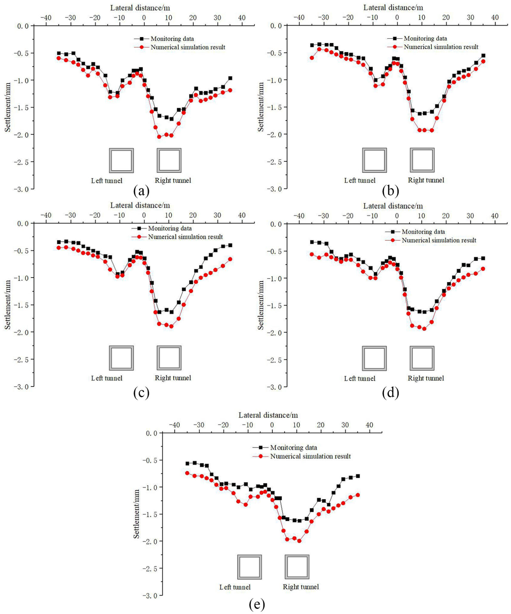
Comparison between lateral settlements of station’s baseplate: (a) characteristic Line 1, (b) characteristic Line 2, (c) characteristic Line 3, (d) characteristic Line 4, and (e) characteristic Line 5.
It can be known from Figure 16 that the actual settlements and simulated ones of existing station’s baseplate are quite close in value and basically accord with each other in variation trend. It again proves the good performance of CD method in controlling the baseplate settlement of existing station. Overall, the actual settlements are slightly smaller than the simulated ones, which also can be attributed to the pre-reinforcement measures based on deep-hole grouting and the jack-up technology.
Discussion and conclusion
The tunnels newly built between Aotidong Station and Aotizhongxin Station of Shenyang Metro Line 9 in Liaoning Province of China are beneath the existing Aotizhongxin Station of Metro Line 2. The vertical distance between the baseplate of the Aotizhongxin station and the new built tunnels is zero. Furthermore, the section of the new tunnels is rectangular with flat roof and upright wall, which is different from the usual circular or elliptical tunnels. In the past decades, amounts of studies have been devoted to investigating the effects of tunnel construction on adjacent structures or facilities, but there are relatively few studies on such project mentioned before. Based on those newly built tunnels, the numerical simulation method was employed to research the settlement laws of the existing station’s baseplate caused by different construction methods. The results of this article can provide some insight into the design and construction for the similar projects in the future.
The main conclusions of the article are as follow:
To analyze the settlement laws of the existing Aotizhongxin station’s baseplate of Metro Line 2 caused by the newly built tunnels between Aotidong Station and Aotizhongxin Station of Shenyang Metro Line 9, four tunnel excavation methods (i.e. full-face excavation method, benching tunneling method, side heading method, and CD method) were employed to simulate the construction process of the newly built tunnels.
According to the numerical simulation results, the maximum settlements of station’s baseplate caused by full-face excavation method, benching tunneling method, side heading method, and CD method are 4.49, 6.83, 2.49, and 2.05 mm, respectively. The overall settlement caused by CD method is the smallest. CD method has an extremely good control over the settlement of existing station’s baseplate and has the best performance in ensuring the safe running of existing station. Therefore, it was suggested to excavate the tunnels through CD method.
The comparison between the numerical simulation results of CD method and monitoring data indicates that they are not only similar in variation trend but also close in value, which proves the superiority of CD method in controlling the settlement of existing station’s baseplate.
Footnotes
Handling Editor: MA Hariri-Ardebili
Declaration of conflicting interests
The author(s) declared no potential conflicts of interest with respect to the research, authorship, and/or publication of this article.
Funding
The author(s) disclosed receipt of the following financial support for the research, authorship, and/or publication of this article: This paper is supported by the National Natural Science Foundation of China (grant nos.: 51578447 and 51404184), the Youth Science and Technology Nova Program of Shaanxi Province (grant no.: 2018KJXX-061), and the Natural Science Basic Research Program of Shaanxi Province (grant no.: 2016JQ4009). The financial supports are gratefully acknowledged by the authors.