
Abstract
The precise control of the two-wheel independent drive motor speed of automated guided vehicle is the prerequisite for high-precision operation of its actuator. The optimization of motor control performance has been a topic of concern to researchers. First, the model identification of direct current motor is done. Second, there are two control strategies, including parallel proportional–integral–differential control strategy and the coupling proportional–integral–differential control strategy, which are researched and compared for the direct current motor control system of automated guided vehicle in dispatching the goods from one location to another with greater ease. Finally, the motion trajectory algorithm of automated guided vehicle is also proposed on the basis of kinematics theory. Besides, the above control strategies and algorithm improved for automated guided vehicle are simulated by the MATLAB tool and the experimental simulations by Kinect sensor, and the simulation results show that the coupling proportional–integral–differential control strategy is slightly better in controlling performance because of some smaller cumulative errors and the better start performance. Meanwhile, the motion trajectory algorithm of automated guided vehicle under both the control strategies can achieve different effects in different control cases.
Keywords
Introduction
During past decades, the concerns over energy shortages and environmental pollution problems have been growing. Compared with diesel engines, new energy electric vehicles have become more and more important because of their features on energy-saving and emission reduction. The main usage of automated guided vehicle (AGV) is dispatching the goods from one location to another with greater ease. Besides, the AGV serves many industries with greater efficacy compared to the manual function and it can be further promoted to the elevation of automation by its artificial intelligence that is being controlled by Bluetooth/Wi-Fi. 1 According to this research, 2 the position and angle decoupled method is the basis of a two-wheel robot (TWR) system, which aims to achieve the asymptotic stability control for a fourth-order nonlinear TWR system using a second-order dynamic model. Meanwhile, Sahoo et al. 3 have designed different optimization control techniques of direct current (DC) motor, including the decision of proportional–integral–differential (PID) parameters using genetic algorithms (GAs) and different control strategies such as model predictive control (MPC) and linear quadratic regulator (LQR), which are used to control the angular speed of DC motor.
To address the motor control problem, the genetic algorithm and fuzzy neural network control (GA-FNC) technology has been applied to the position–speed dual closed-loop PID controlling algorithm, 4 and another optimization technique of PID control for DC motor speed has been presented by Jain et al. 5 Besides, an optimization of PID control for DC motor based on the artificial bee colony algorithm has been researched by Liao et al. 6 The algorithms proposed above also find slight difficulty in getting the ideal control performance, and Abhinav and Sheel 7 have utilized an adaptive robust control performance against the disturbance variations, which obtains an excellent control performance but with a complex control system. In the study of Rigatos, 8 an adaptive fuzzy control has been proposed to improve the performance of DC motor when the output torque of motors or the load condition of AGV has been changed. Therefore, the online tuning gray fuzzy PID (OTGFPID) method, in the study of Liem et al., 9 has been mentioned to estimate the load torque of a DC motor shaft using a novel modeling method based on an adaptive control method. Most researchers such as Peng and Dubay 10 and Aryza et al. 11 also adopt the methods of using the adaptive neural network control and the PID control based on neural network to control the DC motor speed. In addition, a fuzzy neural network (FNN) controller, which behaves like a robust-nonlinear IP controller called FNN-IP controller, has been designed by Dandil 12 just for the position control of induction motor drive and the robustness of the control system. In the study of Nouri et al., 13 a recurrent artificial neural network has been proved for the online modeling and control of the nonlinear motor drive system with high static and Coulomb friction, which obtains the excellent ability of disturbance rejection. In the study of Rigatos, 14 Kalman filtering algorithm has been compared to particle filtering algorithm for state estimation of DC motor and the latter can accurately succeed in estimating the motor’s state vector for a larger number of particles but requires higher computational efforts at the same time. In order to reduce the complexity of the DC motor control system, the output feedback control for robust tracking of position trajectories for DC electric motors has been researched. 15 Hasan et al. 16 have presented the wavelet network-based motion control, which is used to design adaptive speed controller and achieve a high-speed control performance for a DC motor even if the motor model is unknown. Furthermore, a signal neuron adaptive PID 17 has also been applied in the DC speed regulating system by dSPACE platform and the network predictive control (NPC) issue has been proposed by Wu et al. 18 to compensate for the effect of both time-varying delays and packet dropouts. Both fuzzy controller and neural network controller have been designed in the study of Yan et al., 19 which discussed the application of artificial intelligence in the speed regulation of DC motor. In the study of Petru and Mazen, 20 the pulse width modulation (PWM) control of a DC motor used for driving a conveyor belt has also been experimented, which provided the performances settled at the designing stage. In addition, the output feedback trajectory tracking problem for an uncertain DC motor pendulum system under an unknown bounded disturbance has been solved by an algorithm using a proportional–derivative (PD) controller and a novel online estimator of the unknown disturbance by Aguilar-Ibañez et al. 21 And the multiple positioning modules have been used to detect the faults of sensors and actuators of AGV system in the study of Pratama et al. 22 In addition, Gao et al. 23 have treated a novel combination of two controversial control concepts, sign inverting control (SIC) and delay scheduling (DS), for systems with multiple independent and large delays, and the disturbance rejection speed within these enlarged stable regions has also been investigated to improve the control performance. Gao and Olgac 24 have proposed a structured methodology to select the nominal control law with an LQR-based controller and makes the contribution feasible and optimal in some sense. In the study of Wang et al., 25 fuzzy-model-based sliding mode control (SMC) of nonlinear descriptor systems put forward a novel integral fuzzy switching manifold involved with time delay, and the key benefit of this method is that the input matrices via different subsystems are permitted to be diverse, and thus more applicability can be achieved. To fully accommodate the model characteristics of the systems, a novel integral-type fuzzy switching surface function is put forward for fuzzy singularly perturbed systems (SPSs) subjected to matched/unmatched uncertainties, 26 and the applicability and superiority of obtained fuzzy SMC methodology are verified by a controller design for an electric circuit system. To better accommodate the characteristics of T-S fuzzy models, an appropriate integral-type fuzzy switching surface is put forward by taking the state-dependent input matrix into account, 27 which guarantees the asymptotic stability of corresponding sliding mode dynamics with a strictly dissipative performance.
First, the DC motor model is identified by the least-squares method to enhance the stability of motor control system of AGV. Second, we design and compare the control effect of both parallel PID control and coupling PID control strategies. Finally, an algorithm of AGV motion trajectory is also described by equations (20)–(23) in section “Motion trajectory model.” Meanwhile, the feasibility of the motion trajectory algorithm and both the PID control strategies are simulated and analyzed based on the MATLAB tool and experimental architecture, which is shown in Figure 1. The simulation results show that the coupling control strategy can achieve a better control effect and the algorithm can simulate the different motion trajectory of AGV in real time.
DC motor system
Measurement architecture of DC motor speed
As shown in Figure 1, the measurement architecture of DC motor speed consists of a controller, a driver, two motors, and two encoders. Arduino is the controller of the system and outputs the PWM signal to the motor driver. Then, the dual driver drives motors and motors rotate the encoders through coupling, which can transfer the shaft torque of motors. The pulse signal is calculated by the A/B phase of the encoder and sampled in real time by the timing interrupt modules, including enhanced capture timer (ECT) module and period interrupt timer (PIT) module. Meanwhile, the real-time speed of DC motor can be measured and displayed periodically in the host computer. According to the above speed measurement architecture, the closed-loop control strategy of the DC motor speed can be implemented.

Measurement architecture of DC motor speed.
DC motor model
There is no doubt that DC motors are commonly used as actuators in many control systems because it not only provides the larger torque to the load but also has a good start performance and speed characteristics. The free-body diagram of the rotor and the electric equivalent circuit of the armature are shown in Figure 2. As the model describes, the voltage source and the motor speed are the input and output of DC motor system, respectively. The shaft and the rotor are assumed to be rigid.
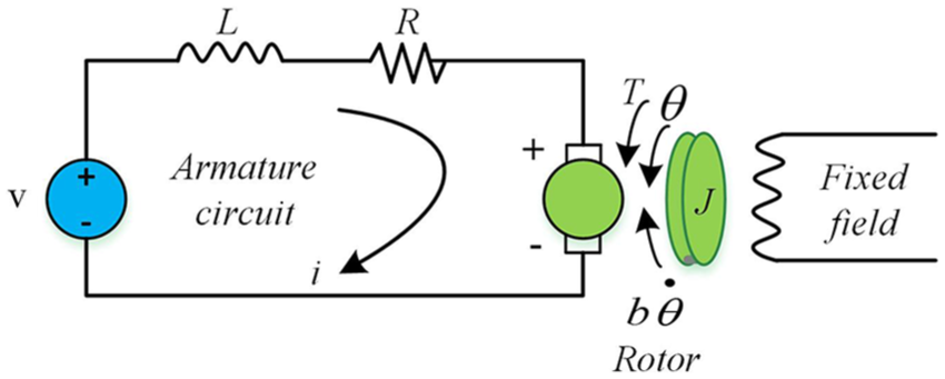
Schematic diagram of DC motor model.
The primary equations can be adopted to describe the DC motor model as follows: 28
1. Torque balance equation
Assuming that the magnetic field is a constant value, and the motor torque is proportional to the armature current by a constant factor

where T represents the motor torque in
2. Electromotive force equilibrium equation


where e is the electromotive force in
3. Newton’s second law and Kirchhoff’s law of voltage (KVL)


where J is the inertia of motor rotor in
4. Laplace transform performed on equations (1)–(5)


5. Therefore, the motor’s open-loop transfer function is a second-order model and shown in the following equation
In equation (8), the rotational speed is the output and the armature voltage is the input.
In general, the inductance of armature windings is very small and the inductance value L can be ignored. 29 Therefore, the first-order model can be described as the following formula according to the equations mentioned above. Besides, the parameter identification of DC motor will be done in the next section

System identification by least-squares method
The least-squares method is adopted to identify the DC motor model before the following studies.
Assuming that A single-input, single-output (SISO) system is shown in Figure 3, and the transfer function of this system can be summarized as below30,31


Schematic diagram of a SISO system.
So, the following equation can be obtained, where

Equation (12) can be expressed as a difference equation

where

According to the observation matrix

where

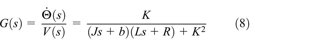
So, the objective function is

Therefore, the partial derivative of the objective function is
If the matrix
Now, several sets of motor speeds at different voltages under experimental conditions are shown in Table 1. According to the least-squares method, the transfer function of DC motor system is

Motor speed of different voltages under experimental condition.

Motion trajectory model
Assume that AGV motion is in the two-dimensional plane coordinate system XOY. The basic motion trajectory model is shown in Figure 4, where
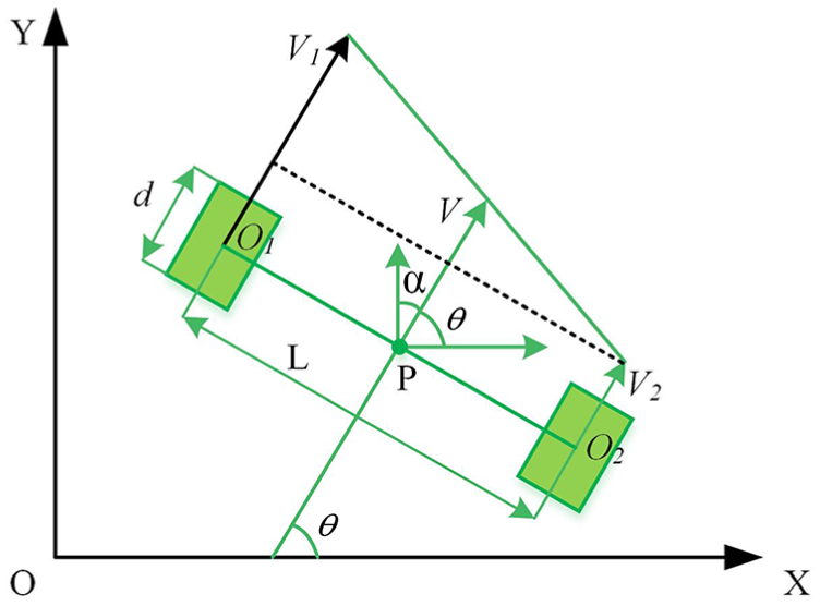
Motion trajectory model of AGV.
Hence, the motion trajectory model of AGV can be established as the following equations 32


where
To enhance the readability of the motion trajectory of AGV, some simple pseudo codes are shown below:
// some simple pseudo codes of motion trajectory of AGV
Begin (Starting the algorithm)
Entering some variables in MATLAB: t, L, X, Y.
Initializing the variable: theta, etc.
IF t, L, X, Y, theta;
Then the position array is Pos(1,:) = [X, Y].
IF V1, V2;
Then renew the values of theta, X, Y, and the position array Pos(i,:) = [X, Y].
IF Pos(i,:) = [X, Y];
Then drawing the motion trajectory of AGV.
End (Ending the algorithm)
where t stands for the sampling period, L represents the distance between the two wheels, X and Y are the trajectory coordinates of AGV, and theta is the angle of sampling time. According to the above variables, the motion trajectory of AGV can be described by the algorithm mentioned above. Besides, the core of the motion trajectory of AGV is the encoders and the reliability of PID control algorithm.
Trajectory tracking of AGV
In this section, the Kinect sensor is adopted to track the movement path of AGV. The schematic diagram of trajectory tracking of AGV is shown in Figure 5. To increase the vision of camera and guarantee the positioning accuracy of AGV, the Kinect sensor is made to hang on the ceiling, which is 2.65 m from the ground. Therefore, the motion states of AGV in Figure 5(a) are tracked in the pixel coordinate and the schematic diagram is shown in Figure 5(b). Meanwhile, the Kinect sensor captures the two-dimensional pixel coordinates by identifying the feature marker located on the AGV, which corresponds to the different states of the AGV while moving. Figure 5(c) shows the top view of the pixel coordinate of AGV captured by the sensor in a certain movement state and the pixel coordinate is (650, 552). The Kinect sensor starts collecting the image coordinates while the AGV starts, and a series of discrete pixel coordinates stand for the discrete motion states of AGV. Hence, the collected image coordinates can fully track the motion trajectory of AGV.

Schematic diagram of trajectory tracking of AGV.
PID control strategies for AGV
PID algorithm
In a continuous system, the control rule of the analog PID controller is shown as follows

where
However, more systems are discrete in practical applications and the PID algorithm can be described as follows.33,34
PID algorithm


where
PID controller
The PID controller is a linear controller, including three control links, which are the proportional control, integral control, and differential control. The subroutine flow chart of PID controller is shown in Figure 6. Besides, PID controller changes the output value just according to the control deviation caused by the set value and the feedback value. Then, the control deviation and the output value of PID controller may be different at different times. Therefore, PID controller can adapt to the control conditions excellently based on its advantages such as strong adaptability and robustness, less dependency on the model, and simple control principles, which is also widely used in industrial manufacturing.

Flow chart of PID controller.
Framework of PID control strategy
The applications of PID control system are different with different control targets. Synchronous control of motor speed plays an important role in many drive systems. 35 Here, two different PID closed-loop control strategies are designed for AGV to control the DC motor speed.
Parallel PID control strategy
The parallel control strategy of motor speed is one of the synchronization control methods, whose advantage is that the synchronization performance of motor control system is better than others during the start and stop phases. As shown in Figure 7, the motors are driven in parallel by the dual driver at the same voltage, and the output value of speed is fed back to the PID controller in real time. Then, the error between the set value and the feedback value is used as the input value to the PID controller. Meanwhile, the voltage control signal is adjusted and sent to the dual driver.

Framework of parallel PID control strategy.
PID control strategy of deviation coupling
Besides, another control strategy called coupling PID control of DC motor speed is designed and described in Figure 8. Its main control idea is that the deviation between the feedback values of motor speeds plusses the set value and the feedback values of speeds, which belong to motors A and B, respectively. And the deviation is used as the speed compensation signal to both motor A and motor B, which is different from the parallel control strategy mentioned above. Furthermore, the control principle of this strategy is consistent with the parallel control strategy.

PID control strategy framework of speed deviation coupling.
Control principle of two strategies
The main control principle of the above control strategies is to ensure the synchronization of the two motor speeds. As observed from Figure 9, the motor speed changes quickly in the initial starting state, and the issue about different speeds between two motors is discussed. The speed of motor B is adjusted to that of motor A and the speed of motor A is adjusted to that of motor B which can be divided into cases ① and ②. Meanwhile, the above control strategies can be further explained as the following equations.

Schematic diagram of PID algorithm.
The parallel PID control strategy is shown in equations (31) and (32), and the main control target is that the value of


Besides, the coupling PID control strategy is depicted in equations (33) and (34), and the main control purpose is that the value of


Simulation and experimental results
Both the PID control strategies proposed for DC motor speed control of AGV are simulated and analyzed in this section. Besides, an algorithm of motion trajectory for AGV is also verified based on an experimental platform and the MATLAB tool. Here, the simulation process can be divided into two parts, control part and motion trajectory part.
Part 1
Figure 10 depicts the change in DC motor speed under the parallel PID control strategy. In the parallel PID control system, the DC motor speed can reach the set value quickly in a short time and remain in a stable state basically in the next period of time. The speed of motor A can be followed by motor B, but the speeds of both motors are not suitable for the response of the motor model. Moreover, it also shows that the change trend of speed of motor A is slightly fluctuated than that of motor B in the whole stable state, but the average speeds of motors are basically stable at 500 rotates per minute (RPM). Besides, Figure 11 shows the control performance curve of another PID control strategy, and the motor speed can also achieve its target value in a short time. However, the difference in the parallel control strategy is that the speed synchronization of the two motors is not very good in the transient process, but remains almost the same constant value after 10 s. Also, the speed change trend of two motors is close to each other in the stable state and better than that in Figure 10.

Parallel PID control strategy of DC motor speed.

PID control strategy of speed deviation coupling of DC motor.
In addition, Figure 12 describes the error curves of DC motor speed under the two different control strategies mentioned above. After the comparison of the two control strategies, the error curve of the coupling PID control strategy changes more evenly but with bigger errors in the transient process, and its convergence is faster than that of parallel control strategy. Then, the cumulative error curves of DC motor speed under the two different PID control strategies can be simulated and shown in Figure 13. The figure displays obviously that the cumulative error curves of parallel PID control shows a nonlinear downtrend with the time passing, which is divergent. So, the above phenomenon reduces the stability of the DC motor system. However, the cumulative error curve of coupling PID control strategy is convergent and close to zero in the whole process. According to the comparison of the cumulative error curves of the above control strategies, the value of cumulative error curve of coupling PID control strategy is lower than that of the parallel PID control strategy. So, both the control strategies have their own certain advantages in control performance of DC motor, but the convergence speed of coupling PID control strategy should be slightly better than that of parallel control strategy.
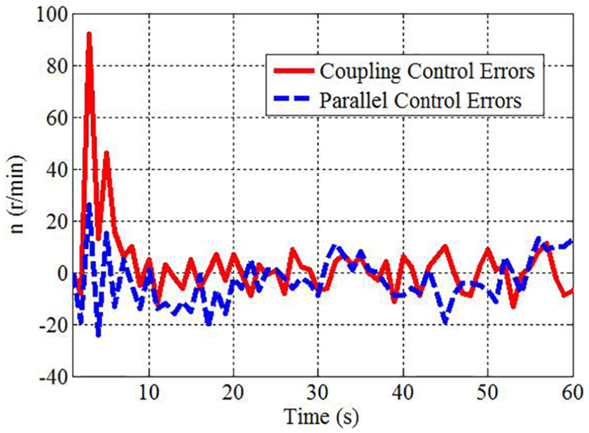
Comparison of motor speed errors under the two control strategies.
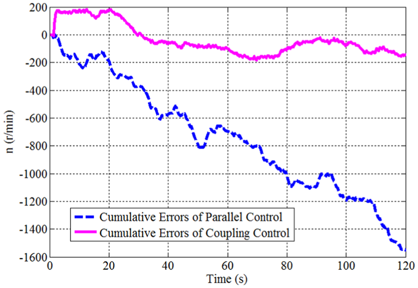
Comparison of cumulative errors of DC motor speed under the two control strategies.
To more precisely verify the reliability and accuracy of the motion trajectory algorithm, an experimental environment of motion trajectory tracking of AGV based on the Kinect sensor is shown in Figure 14. Figure 14(a) shows the experimental panorama, which is close to our lab, and the Kinect sensor is suspended on the ceiling described in Figure 14(b). So, a larger field of view can be seen in the sensor to track the motion trajectory of feature marker installed at the AGV in Figure 14(b) and map the motion trajectory in the pixel coordinate system. Hence, the real-time motion trajectory of AGV can be reflected in the corresponding pixel coordinate system according to the pixel coordinates of the feature marker, which is discussed in the next part.
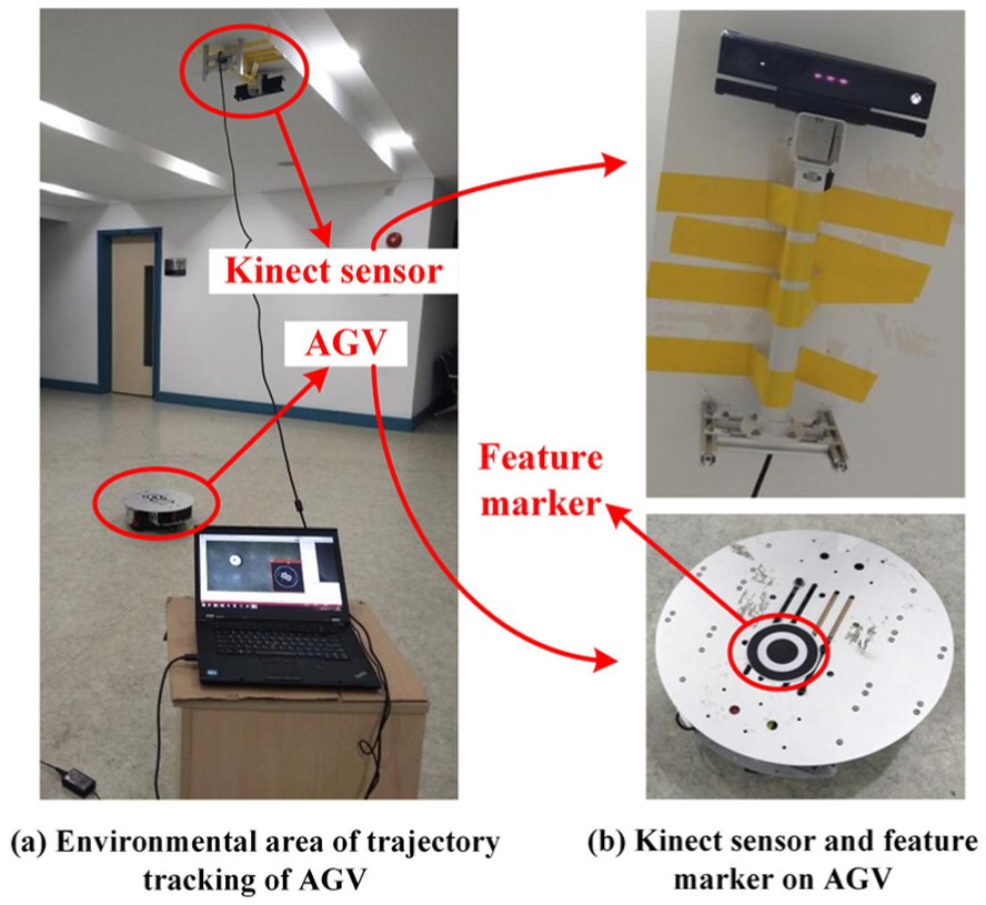
Experimental environment of trajectory tracking of AGV.
Part 2
An algorithm of motion trajectory for the AGV is also proposed to improve the control performance of DC motor in the initial states. Figure 15 represents the real-time motion trajectory of AGV under parallel control based on the motion trajectory algorithm in section “DC motor system.” An important phenomenon is observed in which the trajectory deflects to the right in the initial state and then motion straight in the next section of path. As observed in Figure 16, the experimental simulation curve of the motion trajectory of AGV in the initial transient state marked with an oval in Figure 15 is simulated based on the Kinect sensor. Meanwhile, the real-time motion trajectory was displayed in the form of pixels in the two-dimensional pixel coordinate system, from which the starting process is unstable and slightly turns to the right and then moves straight. The above initial motion trajectory is slightly consistent with Figure 15 and the simulation distance of the initial state is about 4.7 m, which is based on the effective vision of Kinect sensor. Similar to Figure 15, Figure 17 shows the motion trajectory of AGV under coupling control and the initial state is also marked with an oval. Contrary to Figure 15, the trajectory deflects to the left in the initial state and then the next movement is close to the straight line with slight shaking, which may be caused due to the fact that the frictions between the tires and the ground constantly change and the center of gravity of AGV also changes. As observed from Figure 18, the experimental motion trajectory simulation of AGV in the initial state based on the Kinect sensor is close to a straight line, which is described in a two-dimensional pixel coordinate system. Generally, the motion trajectory is slightly biased to the inside, which is consistent with Figure 17 in the initial state marked with an oval. Besides, the simulation distance of the initial state is about 4.3 m.

Motion trajectory of AGV under parallel control.

Initial motion trajectory simulation of AGV under parallel control.

Motion trajectory of AGV under coupling control.
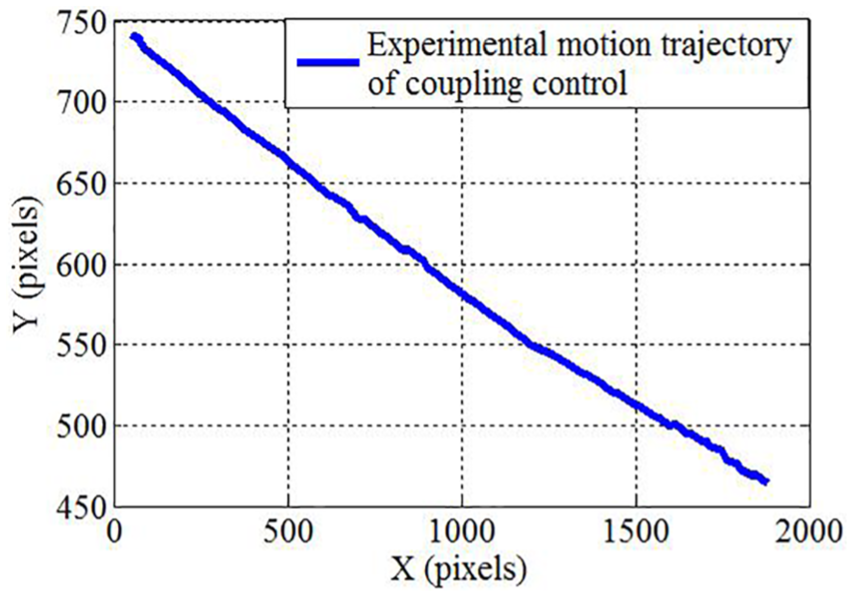
Initial motion trajectory simulation of AGV under coupling control.
From the above researches and simulation results, the coupling PID control strategy is slightly better than the first control strategy because of the cumulative errors as shown in Figure 13. In addition, both the PID control strategies are simulated and the experimental results show that the motion trajectory can be a straight line. Both the control strategies have their own control advantages aiming to achieve different control performance in different control cases.
Conclusion
First, theories of DC motor model and the system identification of DC motor are researched. Second, two control strategies based on PID algorithm are also proposed and simulated, which shows that the coupling control strategy is slightly better in controlling the cumulative errors and the better starting performance in the initial state. Third, the motion trajectory algorithm of AGV is discussed and simulated by the Kinect sensor, which can track the motion trajectory of AGV by identifying the feature marker. In summary, both the control strategies have their own performance in controlling the DC motor speed; the coupling control has a certain advantage in terms of convergence rate; and the motion trajectory algorithm of AGV can be in real time simulated well by some discrete pixels and displayed in a two-dimensional pixel coordinate system.
In the future research, the second-order system and the synchronous control 36 of DC motor will be studied to further improve the accuracy of the DC motor control system. Besides, many other control strategies in literature9,37–39 will be applied in this motor system to enhance the robustness of motor system. Closed-loop scheduling and control of multiple AGVs’ efficiency for energy-efficient inter-terminal transport in the studies of Ho et al. 40 and Zheng et al. 41 are also the further research field. In addition, different observer design methods in the studies of Zhang and colleagues42,43 can be further researched carefully and applied in the DC motor control system.
Footnotes
Acknowledgements
The authors thank the lab teachers and fellows for their precious time and efforts for writing this manuscript.
Handling Editor: Hamid Reza Karimi
Author note
Panlong Zhang is the first author, and Zhongcheng Wang is the second author and the corresponding author.
Declaration of conflicting interests
The author(s) declared no potential conflicts of interest with respect to the research, authorship, and/or publication of this article.
Funding
The author(s) disclosed receipt of the following financial support for the research, authorship, and/or publication of this article: This work was supported by SunQiao Modern Agriculture Group and Shanghai Maritime University, and also supported in part by the Shanghai Science and Technology Committee (17170712100).