
Abstract
An improved method for preventing vortex rope formation and alleviating the associated pressure fluctuations in turbine draft tubes is investigated using baffles in the draft tube to hinder the swirling flow emerging from a Francis turbine runner. A strong swirl produces flow instabilities and pressure fluctuations. Partial load operating conditions at the rated water head and three flow rates are taken into consideration. It is demonstrated using a computational fluid dynamics simulation that this method effectively eliminates the vortex rope, particularly when using four baffles. The amplitude of the pressure pulsation in the draft tube modified with four baffles was 0.42 times that in a traditional draft tube. The baffles were found to reduce the tangential velocity of the flow in the draft tube and consequently hinder the development of the fierce swirling flow. This type of decrease is more significant compared to the gradual decay due to viscous effects of the solid wall in a traditional draft tube. The conclusion was verified by the results of experiments conducted using a novel device. The measured increase in turbine efficiency exceeded 3% at the evaluated partial loading point, indicating improved economic performance of the turbine.
Keywords
Introduction
Hydropower is a readily available source of renewable energy 1 and currently accounts for a significant portion of electricity generation worldwide.2–4 The use of hydropower and other forms of renewable energy such as wind energy, solar energy and geothermal power are rapidly expanding due to their renewable properties and generation without aggravating the greenhouse effect.5,6 Unfortunately, the unpredictable and volatile nature of many renewable energy sources could have an adverse effect on the coordination of energy supply and demand and potentially lead to the tremendous instability of the electrical grid. 6 As a consequence of this unpredictability, the hydropower station has become increasingly indispensable in improving the flexibility and reliability of a renewable-powered electricity distribution network, providing smooth integration of intermittent renewable energy sources into the existing power grid. When hydropower plants are operated for peak regulation and frequency modulation, hydraulic turbines tend to operate over an extended range of regimes quite far from their best efficiency point (BEP), which can lead to unfavourable issues, including reduction in the overall efficiency of the turbine, rotor–stator interaction (RSI), cavitation, vortex breakdown, and severe vibration and noise. 4
The Francis turbine, a commonly employed type of hydraulic turbine, is generally designed for an optimum BEP for a certain discharge. At this operating point, there is insignificant tangential velocity, and the Francis turbine operates with few swirls and no flow separation. However, in engineering practice, a Francis turbine is often engaged in off-design conditions, so that the flow leaves the runner with a high residual swirl, that is, the tangential component of velocity (Vθ) is not zero. The more considerable Vθ is, the more likely hydraulic instabilities are to occur. 4 Unstable swirling flow in the draft tube can result in the formation of a helical precessing vortex, also known as the vortex rope, which leads to a reduction in efficiency and severe pressure fluctuations in the entire hydraulic system.
In the past several decades, both experimental and numerical researches have been conducted to explore the mechanism of vortex rope formation and corresponding control measures to reduce its impacts on the entire hydraulic circuit. Seidel et al. 7 summarized the flow physics under different operating conditions of a Francis turbine, finding that the flow pattern in the draft tube was characterized by swirl, flow separation and backflow. Su et al. 8 presented the patterns of vortex ropes in the draft tube at varying operating points and discovered that the greater the deviation from the optimal point, the larger the volume of the vortex rope. The rotating vortex rope (RVR) frequency has been observed to vary from 0.2 to 0.4 times the runner rotational speed. 9 Typically, the measurement of wall pressure has been performed by mounting pressure transducers at different locations in the turbine, which may not provide sufficient information to comprehensively investigate flow instabilities: Trivedi et al. 10 observed an asymmetrical flow leaving the runner after detecting an instantaneous pressure difference between two sensors located in the draft tube cone section. More recently, particle image velocimetry (PIV) has been applied to reveal the physical characteristics of the flow at various operating conditions.4,11,12 Iliescu et al. 13 employed PIV to investigate the flow in hydraulic turbines under off-design operating conditions. They noted that the tangential component of the velocity was significant under the partial load condition in the draft tube, thus leading to vortex breakdown.
Despite the aforementioned studies conducted by researchers around the world, there remain some problems related to experimental investigations yet to be resolved; for example, the pressure amplitudes may be large in model turbines but are usually non-existent in prototypes. In addition, experiments performed in a model turbine or prototype can be time-consuming and expensive, and it is typically quite difficult to conduct these tests. Recent progress in numerical simulation techniques has made it possible to accurately predict unsteady fluid flow in hydraulic turbines without the difficulties of models. At present, it is generally acknowledged that computational fluid dynamics (CFD) can be applied not only to advance the understanding of such dynamic fluid flow effects, but also to optimize the design of turbine components.14,15
There are three common control methods that are effective in alleviating the pressure fluctuations induced by a vortex rope: air or water injection,16,17 runner cone extension 18 and stabilizer fins mounted on the draft tube wall. 19 Experiments have shown that inappropriate air or water injections are likely to enhance the pressure pulsations. For instance, S Muntean et al. 20 found that the dynamic behaviour was seriously deteriorated with air injection control method if this Francis turbine operates at lower discharge (around 0.5QBEP). The maximum amplitude on the draft tube cone wall increased up to twice under this operating point compared to the case without air injection, thus leading to mechanical problems. Moreover, a considerable power is required for injection of compressed air to the draft tube in the case of low-head installation of a hydraulic turbine. 21 The extension of the runner cone can be prohibitive given other physical design constraints on turbines. As for installation of fins in the inlet cone of a draft tube, it is a popular approach to the alleviation of the pressure surge while the mechanism is not fully explained; therefore, Nishi et al. 19 experimentally investigated the effect of fins on the half load surging by analysing wall pressure fluctuations in 1996. In the experiment performed by Nishi, an elbow draft tube made of transparent plastic was used in the study; four fins were mounted on the diffuser cone in order to investigate their influence over pressure fluctuation. Regarding the configuration of fins, two common fins with different cross-section shapes were discussed respectively. However, it was found out that mounted fins were liable to bring about serious losses in efficiency, were subject to cavitation erosion and were able to increase structural vibrations. 17 Nevertheless, considering the benefits of easy installation and no additional hydraulic losses, the use of fins mounted on the draft tube wall offers a good option for reducing the flow instability in the draft tube; therefore, relevant research on the use of fins should be further conducted.
To address the shortcomings in existing study of vortex control methods, the objective of this article was to explore an effective control method for mitigating the appearance of the vortex rope and the associated pressure fluctuations in the draft tube when a Francis turbine operates at partial load. On the basis of previous research by Nishi et al., 19 a small improvement was made to the fin method by replacing the fins with baffles, which are often used in chemical engineering. 22 After verification of the unsteady three-dimensional flow simulations in a traditional draft tube, flow in the modified draft tube of a Francis turbine operating at three guide vane openings (GVOs) was investigated, so as to examine the ameliorating effect of the baffles. The physical mechanism behind the effect of the baffles in alleviating the vortex rope effect was then analysed using a novel device designed to experimentally verify the function of the baffles.
Modelling methods
Numerical turbine model
Computational domain and grid
The complete flow passage of the Francis turbine in the current simulation is shown in Figure 1(a). The technical specifications of the Francis turbine investigated in this study are as follows. The rated head of the turbine was 116 m. The computational domain was composed of a spiral case, a runner integrated with 16 blades, 24 stay vanes, 24 guide vanes and an elbow draft tube. X-shaped blades were adopted for the runner, which was designed to adapt to a wide variation in water head with relatively stable operation and excellent cavitation performance. 23 A GVO of α0 = 16° was used in the simulation and the subsequent experiments. The rated rotational speed was 250 r/min, corresponding to a rotational frequency of 4.17 Hz.
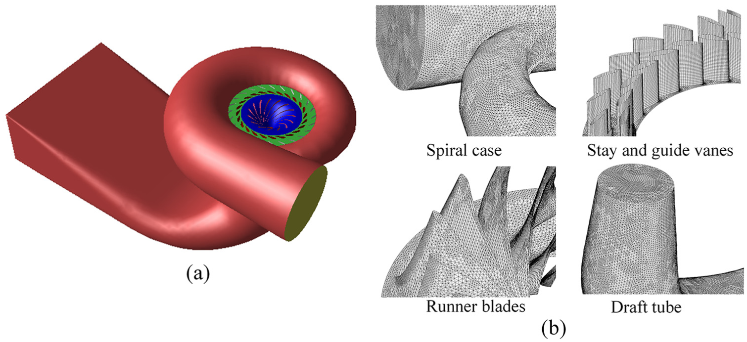
Schematic diagram of turbine investigated and grid cell of main components: (a) total computational domain and (b) grid cell of four primary components.
Hybrid meshes were generated for different domains via the ANSYS ICEM 14.0 software. The spiral case, runner and draft tube were discretized using tetrahedral grids, while wedge grids were used in the vane diffuser. Special refinements were applied to the runner blade and guide vane domains. Figure 1(b) depicts the meshes of the primary components investigated. The grids for various schemes with different draft tubes differed only in the draft tube domain. A mesh sensitivity analysis was performed to verify that the results were independent of the element numbers employed in the CFD simulations. For this purpose, four mesh resolutions of various densities were created for the CFD domain consisting of 1.13 × 10⁶, 2.07 × 10⁶, 3.80 × 10⁶ and 5.94 × 10⁶ elements. The volume flow rate and output of the turbine were selected as reference variables to conduct the mesh independence analysis. As can been seen from Figure 2, the variations in flow rate and runner torque between the four cases are insignificant, indicating that the numerical simulation results are reasonable and credible. In consideration of both computational accuracy and time cost, the fine mesh with a total of 5.94 × 10⁶ elements was chosen for the CFD analysis model. The mesh characteristics created for the complete flow passage model are summarized in Table 1.

Results of the mesh independence analysis.
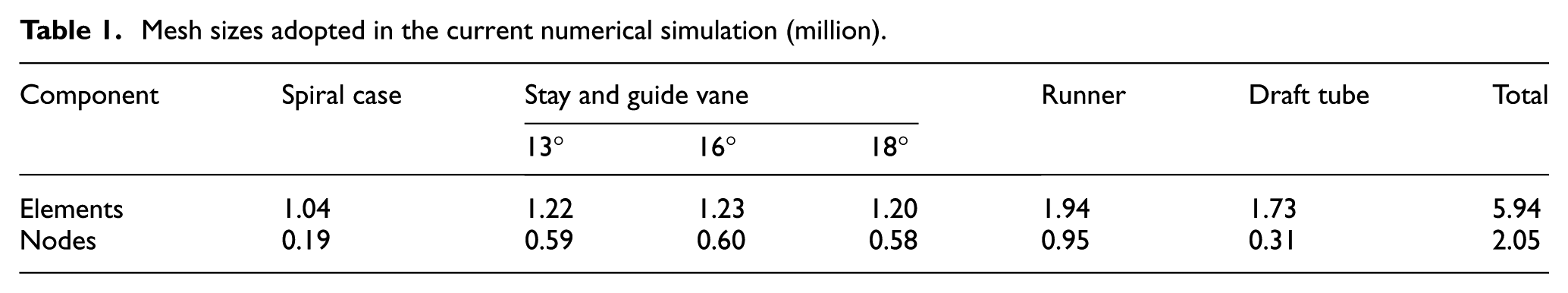
Mesh sizes adopted in the current numerical simulation (million).
Modified draft tube with baffles
The location and dimensions of the baffles mounted on the wall of the draft tube cone are shown in Figure 3. In this study, scenarios consisting of two, three and four baffles uniformly distributed along the circumference of the conical diffuser were investigated. The radial length of the baffle was equal to one-tenth of the diameter of the draft tube inlet. The baffles were installed 2.5 m below the draft tube inlet, and their lengths reached the elbow portion of the draft tube in order to avoid strong interactions with the runner, minimizing the impact of local RSI on the frequency of pressure fluctuations. 19

Sketch of modified draft tube with (a) two baffles, (b) three baffles and (c) four baffles.
Recording points and sections
Eleven points located in the spiral case, near the guide vanes, and in the draft tube (see red dots in Figure 4) were selected to record the time-resolved pressure. Point a1 located 2.35 m below the draft tube inlet is specifically discussed in Part 4 of this article. Four sections, S1, S2, S3 and S4 (indicated in Figure 4), were chosen to analyse the pressure distribution in the draft tube cone. Section S1 was located 2 m below the draft tube inlet and the subsequent sections were spaced at 1 m intervals down the tube.

Schematic diagram of monitoring sections and points.
Numerical turbulence model, scheme and boundary conditions
The three-dimensional incompressible turbulent flow was solved by Reynolds-averaged Navier–Stokes (RANS) simulation, along with the re-normalization group (RNG) k–ε turbulence model and standard wall function.24,25 The RNG-based model claims to be more responsive to the effects of rapid strain and streamline curvature than the standard k–ε model. 25 A steady-state simulation was performed using the same CFD domains and the results were adopted as the initial conditions for the unsteady simulations. During the course of the steady-state simulation, the multiple reference frame model was applied to the runner zone, while during the transient simulation, the sliding mesh approach was employed to obtain a time-accurate solution for the strong RSI between the runner and the guide vanes, and between the runner and the draft tube. The governing equations in space were discretized employing the finite volume method. The SIMPLEC algorithm was chosen to achieve the coupling solution for the velocity and pressure equations. A second-order upwind scheme was applied to the convection terms and a central difference scheme to the diffusion terms in the momentum equations. 26
All simulations were conducted using commercial CFD software package Fluent. Fluent is a general finite volume code that can be used to model a wide range of fluid flow problems. 27 The time-step was set to 0.002 s, corresponding to the time it took the subject runner to rotate 3°, which was deemed to be sufficient to obtain fine time resolution for the dynamic analysis.9,17 The maximum number of iterations per time-step was set to 60 and the convergence criterion of the residuals at each time-step was 0.001. The total simulation time was selected as that necessary for the runner to revolve 20 times.
The boundary conditions used for the flow simulation were defined as follows: total pressure was defined at the spiral case inlet and static pressure was set at the outlet of the draft tube. A non-slip boundary condition was applied to the walls.
Physical draft tube model
In the previous contribution from Nishi et al., 21 they came to the conclusion that the existence of a runner is dispensable for dealing with the pressure surge in a draft tube. This practice of using a set of stationary guide vanes to introduce a clockwise swirl in the flow instead of a runner was used as a reference in the present experiment. Hence, a novel device was contrived to reasonably reproduce vortex rope, as well as replicate the effects of the baffles on the presence of the vortex rope, to confirm results of the numerical model and better understand the function of the baffles in improving the flow inside the draft tube. A picture of the device utilized in this study is presented in Figure 5: a hollow cylinder was constructed of transparent Plexiglas to provide visual confirmation of the vortex structures in the flow domain. The specifications of the apparatus are as follows. The 0.3m-diameter hollow cylinder was mounted with two symmetric, rectangular cavities along the outer shell, in which baffles could be inserted and their protrusion into the cylinder could be adjusted. In the process of experiment, screws were turned based on the scale so as to reach particular length of baffles which were accordingly inserted into the cylinder; note that the screws were fixed onto two screw holes in respective cavity. At the top of the hollow cylinder, two centro-symmetrical inlets and stay vane cascade were deployed to supply stable tangential inflow for the sake of simulating the swirl flow at the runner outlet. The outflow was taken by a 0.02 m diameter hole in the bottom of the hollow cylinder. The effect of the baffles on the presence of the vortex was then analysed with respect to the protrusion of the baffles. For the purpose of clearly determining the effect of a single factor, that is the protrusion of the baffles into the cylinder in this case, other variables such as the inlet and outlet boundary conditions were held steady. The outcomes of the tests were all measured 1 min after the change in the protrusion of the baffles, at which point the flow was assumed to have reached its new dynamic equilibrium state.

Sketch of experimental set-up: (a) transparent Plexiglas cylinder and (b) device for supply of the tangential inflow.
Results and discussion
Assessment of unsteady three-dimensional flow simulations in the conventional draft tube of a Francis turbine
In this section, in order to confirm the quality of the numerical methodology, simulation results of a Francis turbine with a conventional draft tube are compared with the numerical and experimental solutions under partial load obtained from previous literature. Three partial load operating points including 13°, 16° and 18° GVOs were selected due to the generation of well-developed vortex rope and large pressure pulsations under these scenarios, 28 whose flux corresponds to 51.9%, 66.5% and 75.2% of the rated flow rate, respectively. Once the numerical solutions were validated against experimental results presented in the literature, the CFD model could not only be employed to gain a better understanding of the flow behaviours within the draft tube, but also to analyse the performance of the baffle-modified draft tube.
The iso-surfaces of swirling strength, λ3D, were adopted to illustrate the evolution of the vortex structure. A scenario in which the swirling strength equals zero indicates that vortices have definitely not arrived, implying that the local flow regime is laminar. 29 For the sake of consistency, the iso-surfaces of swirling strength equal to 0.01 s−1 were displayed in all cases. After comparing various methods of generating iso-surfaces, it was determined that the iso-surfaces of swirling strength equal to 0.01 s−1 are quite similar to the iso-pressure surfaces of −18 kPa. In addition, a significant number of previous studies have shown that this indicator, which isolates regions of fluid swirling around an axis, can be utilized to consistently yield a regular and identifiable vortex structure in the present scenario under varying conditions.30–33
Figure 6 depicts the vortex ropes generated at three different GVOs. It is observed that vortex rope in the draft tube appears in different shapes at varying operating points; the more deviation from the optimal point with decreasing GVO, the larger the volume of vortex rope. Qualitatively speaking, the general pattern of vortex rope agrees fairly well with other numerical and experimental visualizations in terms of wavelength and diameter.8,9,33–35 However, the actual sizes of these vortex ropes, such as local diameter, length and volume, are quite different from each other. As the focus of interest in this article is the function of baffles mounted on the draft tube cone, the quantitative analysis of the distinction is not discussed in this article.
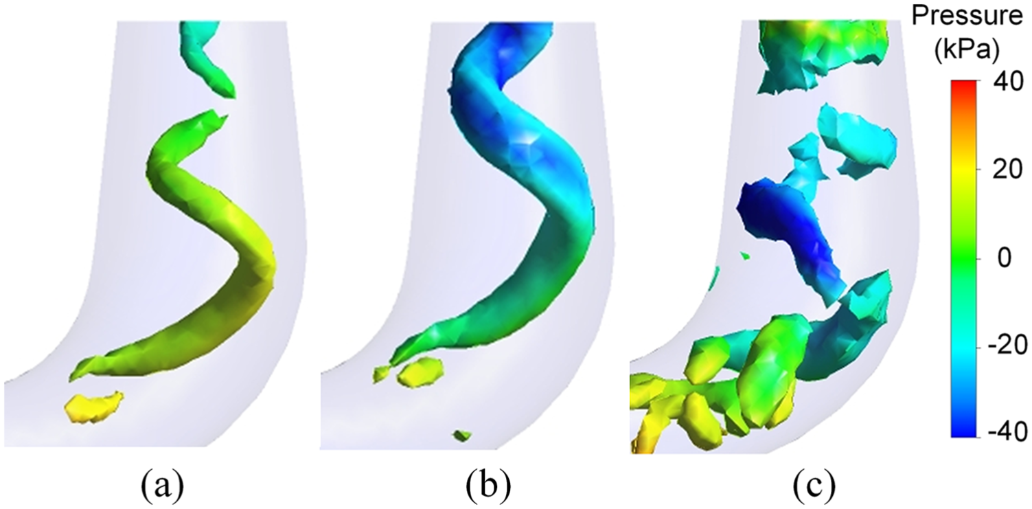
Visualization of vortex rope in traditional draft tube: (a) 18° GVO, (b) 16° GVO and (c) 13° GVO.
During the partial load operation of a Francis turbine, the formation of a spiral vortex core is associated with violent pressure fluctuations in the draft tube. Figure 7(a) depicts the variation in wall pressure with time at point a1 located 2.35 m downstream of the draft tube inlet. Simulations were performed for more than 4 s (2000 iterations) to guarantee that a well-converged solution was obtained. In this research, the results were extracted from the periodic unsteady (quasi-steady) state. Pressure fluctuations brought about by the vortex rope exhibited low frequency and high amplitude characteristics, as shown in Figure 7(b). The dominant relative frequencies

Pressure fluctuations in the traditional draft tube (16° GVO): (a) time history record and (b) normalized frequency spectrum.
Unsteady three-dimensional flow simulations in the modified draft tube of a Francis turbine
To assess the performance of the modified draft tube, the numerical results from the modified draft tube were compared with those from the traditional draft tube. Both draft tubes were compared under three partial load conditions, respectively. In order to determine whether the mounted baffles in the conical diffuser compromised the performance of the Francis turbine, four indices were evaluated: volume flow rate, runner torque, runner output and hydraulic efficiency. These indices were calculated as follows. The volume flow rate can be obtained by means of the surface integral (one of the functions of Fluent). With the Moments report function provided by the post-processing module of Fluent, the summation of the torque around the rotational axis borne by the runner blade surface can be calculated. Consequently, the efficiency and output of the turbine can be acquired in accordance with equations (1) through (3). The effects of the three different modified draft tube baffle configurations on the performance of the turbine were then examined based on the four indicators, as presented in Table 2. Note here that the total pressure difference between the spiral case inlet and the draft tube outlet is set the same in different cases to ensure that the number of baffles is the sole variable

where H is the total water head,

where

where N is the runner output.
Performance of turbines with different baffles (16° GVO).
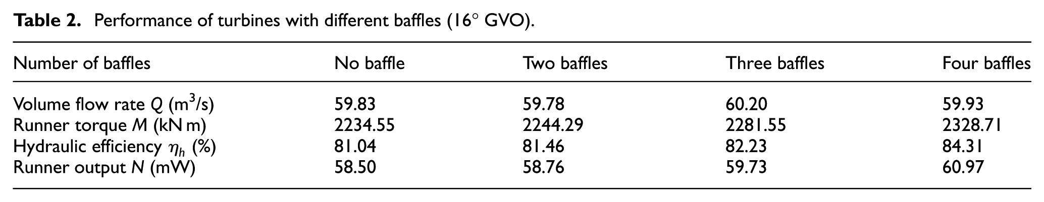
As shown in Table 2, the variation in volume flow rate does not correlate closely with the number of baffles. The differences in volume flow rates between these cases are within 0.70%. In view of the neglect of mechanical and volumetric losses in the course of the simulation, the overall efficiency of the turbine can be approximated by the hydraulic efficiency. The efficiency of the turbine with the traditional draft tube was 81.04%, while the efficiency of the turbine with the four-baffle modified draft tube increased slightly to 84.31%. The rise in efficiency exceeded 3% at 16° GVO. Clearly, the modification of the draft tube with baffles can reduce the payback period and enhance the economic performance of a hydropower plant. Furthermore, as the resulting fluctuation in turbine output was comparatively small, improved stability of power generation can be realized and the life span of the hydraulic equipment will be extended.
The function of the modified draft tube can be demonstrated by comparing the vortex rope within the draft tube cone of the two schemes. As shown in Figure 6, the vortex rope extends along the entire length of the diffuser cone of the traditional draft tube. Characterized by a corkscrew shape with a precession movement, the helical vortex rope begins close to the discharge cone and disintegrates at the junction of the cone and the elbow. However, in contrast to Figure 6, the extent of the precessing helical vortex in the modified draft tube, presented in Figure 8, is significantly inhibited. Despite the fact that the swirling strength at the modified draft tube inlet is similar to that shown in Figure 6, the vortex structure fails to evolve into an intact vortex rope due to the baffles installed in the draft tube cone.
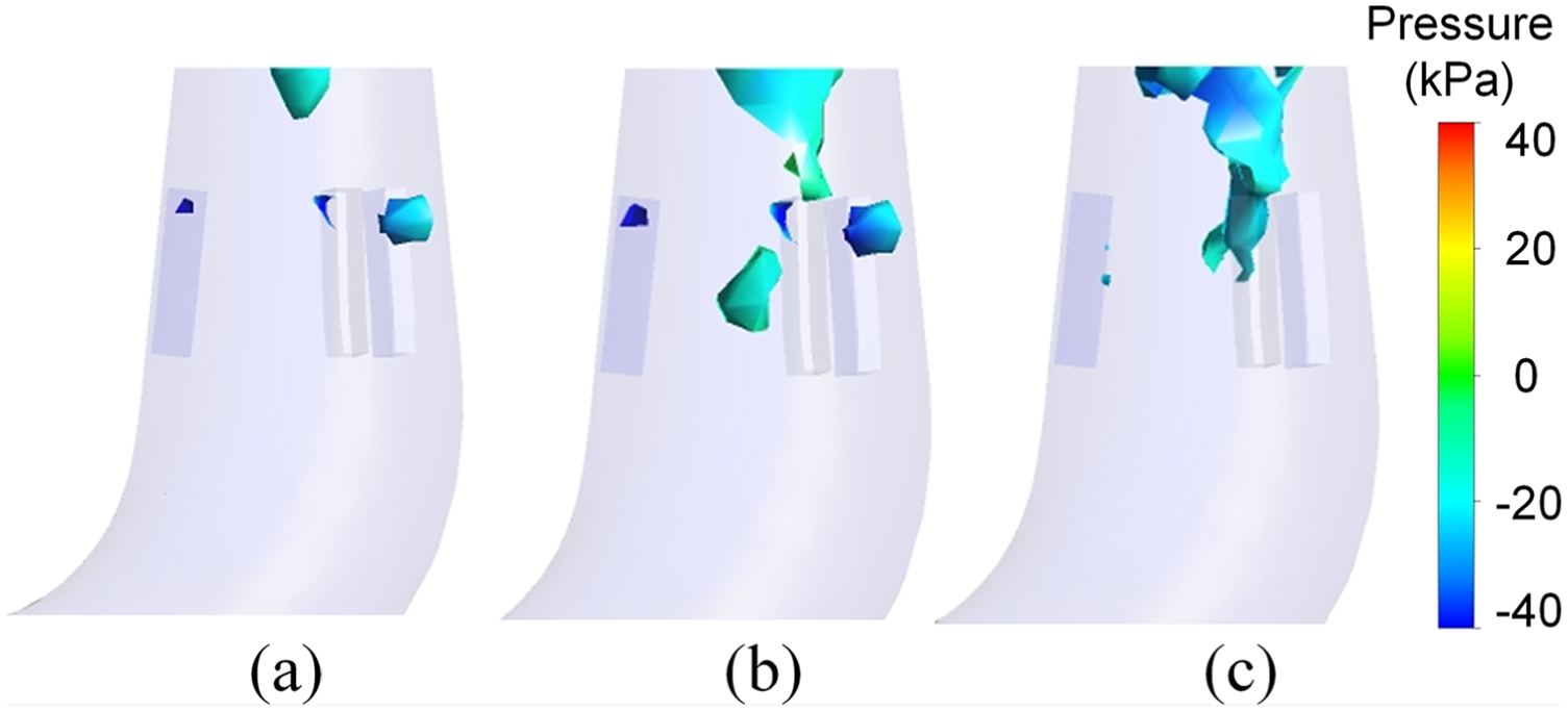
Visualization of vortex rope in modified draft tube: (a) 18° GVO, (b) 16° GVO and (c) 13° GVO.
To provide a thorough grasp of the impact of the baffles on the alleviation of the RVR, the evolution of the vortex rope over time (visualized by the iso-surfaces of swirling strength) at 16° GVO in two different draft tubes is presented in Figure 9. The figures are recorded in sequence starting at t = 1.66 s for an elapsed time of 0.36 s. As shown in Figure 9(a), the geometry of the RVR is almost cylindrical, accompanied by a very small eccentricity close to the discharge cone. The evolution of the vortex rope indicates a periodic nature in which the helical vortex rotates in the same direction as the runner at the inlet of the draft tube. Furthermore, vortex shedding can be observed in the lower part of the conical diffuser. In contrast, the vortex rope in the modified draft tube shown in Figure 9(b) exists on only a small scale. The vortex rope extends approximately the length between the inlet of the draft tube and the upper surface of the baffles. In light of this evidence, it can be inferred that the violent pressure pulsation derived from the RVR would be relieved to a certain degree by the baffles, and that the intensity of unfavourable structural vibrations and noise would be reduced.
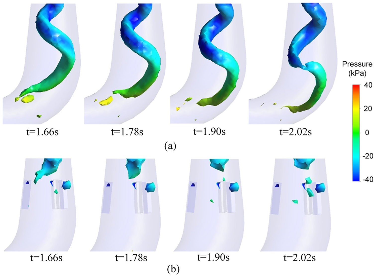
Evolution of the vortex rope with time between 1.66 and 2.02 s: (a) traditional draft tube and (b) modified draft tube with three baffles.
The influence of the draft tube modified with two baffles on the pressure pulsations at point a1 is represented in Figure 10. As previously discussed, low frequency and high amplitude pressure fluctuations are triggered by the vortex rope formation. The baffles mounted in the draft tube cone act to significantly reduce the pressure pulsation amplitude, as illustrated in Figure 10(b). Compared to Figure 7(b), the peak-to-peak amplitude of the pressure fluctuation in the draft tube modified with three baffles is decreased by roughly half, from 17,319 to 9250 Pa. Nevertheless, the change in the dominant frequency of the pressure fluctuations is negligible: the frequency ratio with baffles was 0.32, still in the range of 0.2–0.4 times the runner rotational frequency.

Pressure fluctuations at point a1 in the modified draft tube with three baffles: (a) time history record and (b) normalized frequency spectrum.
The effect of the number of baffles on the flow regime in the modified draft tube is shown in Figure 11. It is apparent from the illustration that two, three and four baffles all contribute to a reduction in the pressure pulsation amplitude, with the four-baffle alternate providing the most noticeable reduction. The pulsation amplitude in the draft tube modified with four baffles is merely 0.42 times the amplitude in the traditional draft tube. The dominant frequency of pressure fluctuations remains invariant in all three baffle configurations, presumably a result of the use of the same runner rotational speed and turbine design.

Pressure fluctuations of the normalized frequency spectrum in the (a) traditional draft tube, (b) modified draft tube with two baffles, (c) modified draft tube with three baffles and (d) modified draft tube with four baffles.
Mechanism of baffle improvement of the flow pattern in the modified draft tube
This article proposed a modified method for suppressing the development of the draft tube vortex rope by mounting baffles in the draft tube cone. The physical mechanisms of this suppression have been determined by subsequent analysis. In Figure 12(a), the radial distribution of circumferential velocity at the traditional draft tube cone is indicated by green scatter; the red scatter delineates the circumferential velocity at the inlet of the modified draft tube. The velocity distribution in Sections 1 and 3 is capable of demonstrating changes of tangential velocity along the draft tube axis. In general, the velocity field demonstrates a higher tangential velocity between the vortex centre and the cone wall, coinciding with findings presented in previous studies.38,39 Comparing the two green scatter plots, it can be seen that the solid wall in the traditional draft tube plays a minor role in diminishing tangential velocity. This decrease in vortex circulation away from the runner outlet in the direction of the flow represents a gradual decline in the vortex strength on account of viscous effects. 37 Nonetheless, the viscous effects that appeared in the conventional draft tube were far from sufficiently intense to destroy the development of the vortex circulation. On the other hand, when the two red scatter plots are taken into consideration in conjunction with the two green ones, it can be found that the baffles mounted in the modified draft tube cone result in a far smaller tangential velocity. The root cause of this reduction is as follows. The baffle is capable of preventing tangential flow in the baffle-intervention region. Moreover, the resulting circumferentially stagnant zone is able to greatly increase the viscous losses of the swirling flow, which is away from the baffle-interference area. In other words, the baffle plays an important role in intensifying viscous dissipation and consequently hindering the development of the helical vortex rope.

(a) Circumferential velocity distribution in S1 and S3 of the draft tube. Note: coordinates are dimensionless parameters. (b) Contours of the instantaneous axial velocity field.
The evolution of the helical vortex rope is connected with formation of a stagnation zone, in which the flow is stalled or even reversed along the centreline of the draft tube as a result of the wake of the crown cone. 40 Figures 12(b) illustrates the instantaneous axial velocity contours on the meridian plane of the traditional and modified draft tubes, respectively. For the draft tube without baffles, a substantial portion of the reverse flow (indicated in red) appears surrounding the central axis of the draft tube. This phenomenon can be explained by the presence of a strong shear layer resulting from high axial velocity gradients (Kelvin–Helmholtz instability) between the stagnant region and the swirling outflow near the centreline of the draft tube. By comparison, the draft tube with the baffles exhibits an increase in the axial momentum of flow in the middle of the draft tube, leading to considerable shrinkage of the central area of dead water, in which only limited stagnation can be observed within the draft tube inlet. In addition, a couple of small-scale stagnation positions can be observed in the cone segment, representing the presence of cavitation pockets. The restraint of the stagnation zone is an important feature connected to the disappearance of the vortex observed in the draft tube. The velocity gradients between the stagnant region and the outer flow decrease with the increase in the axial flow momentum within the centre of the draft tube; the decreased velocity gradient reduces the potential for the shear layer to roll up and hinders the formation of the helical vortex rope. Furthermore, because the rotational frequency of the turbine runner remains constant, the dominant frequency of the pressure fluctuations does not change. It is essential to adopt countermeasures to guarantee that the frequency of these pressure fluctuations is far from the natural frequency of the power-plant structure in order to avoid resonance and prevent consequent fierce vibration of the turbine unit or plant. In this context, the utilization of baffles to control the formation of the vortex rope is promising for the case investigated.
The practicality of this innovative technique becomes more explicit when comparing the static pressure field in several cross sections at different vertical coordinates (shown in Figure 13). As discussed in prior literature, 40 these fields are capable of reflecting the flow regime in different sections of the draft tube. The vortex centre is designated by the minimum pressure point, that is, the bluest region shown in Figure 13. As illustrated by Figure 13(b), the vortex centre can only be identified in Sections 1 and 2; the helical vortex rope has disappeared in Sections 3 and 4. In other words, the pattern of the vortex rope has undergone a transformation in terms of the strength and diameter of the vortex trajectory, and the pressure oscillations have been ameliorated accordingly. Basically, the baffles mounted inside the draft tube cone are able to ensure the safety and stability of the Francis turbine by diminishing the amplitude of pressure oscillations. This observation clearly suggests that the origin of the draft tube vortex rope lies in the inevitable appearance of swirling flow instability in the diffuser cone under partial load operating conditions.

Instantaneous static pressure field in four sections at different vertical coordinates: (a) traditional draft tube and (b) modified draft tube with four baffles.
Experimental verification of the role of the baffle in alleviation of vortex rope
The function of the baffles in improving the flow pattern inside the draft tube was elucidated by an experimental investigation conducted using the novel hollow cylinder device described in section ‘Physical draft tube model’. The effects of varying the insertion of the baffles on the development of the vortex structure inside the hollow cylinder are shown in Figure 14. In Figure 14(a), in which baffles were not applied, a precessing helical vortex was generated in the centre of the flow region. The vortex rotated around the centre axis of the cylinder and was accompanied by severe noise. Furthermore, the shape and the centre of the vortex rope remained relatively stable over the typical precession period. When the baffles were inserted 0.5 cm into the cylinder, the volume of the vortex rope decreased slightly, as shown in Figure 14(b). This phenomenon was accompanied by a decline in the angular velocity of spin and a corresponding decrease in the decibel level of the noise. The vortex structure wobbled along the length of the cylinder and a non-axisymmetric mode dominated in this case. Figure 14(c) depicts the flow pattern in the apparatus with baffles inserted 1 cm into the cylinder. The flow field demonstrated a critical state of swirl configuration, in which small cavitation bubbles were regularly formed. The vortex rope deviated from the centre of the flow field, but the flow field as a whole remained in a relatively stable state. In the final scenario, the baffles were inserted 1.5 cm into the cylinder (Figure 14(d)) and the vortex rope disappeared completely with the circular swirl flow barely being visible. This behaviour supports the conclusions that mounted baffles of sufficient protrusion into the draft tube possess the ability to eliminate the vortex rope and mitigate the pressure fluctuations brought about by intense swirling flow. The practicality of the baffle in removing the vortex, suggested by numerical analysis, was thus confirmed by these experimental results. Finally, it is important to note that the determined dimensionless ratio (0.1) of the baffle protrusion to the radial size of the flow field required to prevent the formation of the vortex rope can serve as a reference for physical model experiments that are not equipped with a turbine runner.
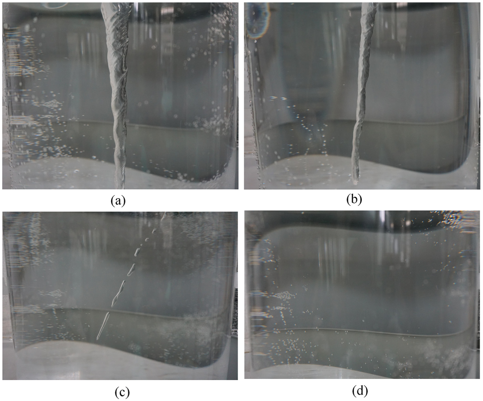
Development of the vortex rope with changes in the protrusion of the baffle: (a) no baffle, (b) 0.5 cm baffle protrusion, (c) 1 cm baffle protrusion and (d) 1.5 cm baffle protrusion.
Conclusion
The use of baffles installed on the draft tube wall of a Francis turbine to control the development of the vortex rope was numerically and experimentally investigated. The flow properties at wide operating range of partial load with rated water head and three different GVOs were considered. Focusing on developing a CFD model, unsteady three-dimensional (3D) flow simulations of the traditional draft tube were performed and verified through comparison between experimental behaviours and numerical solutions in previously published literature. Good consistency among all results was obtained, demonstrating that the settings used in the CFD simulation were reasonable and reliable for the subsequent analyses of the baffle-modified draft tube. The results of the unsteady 3D flow simulations of the baffle-modified draft tube indicated that the violent pressure pulsations generated by the RVR were relieved to a certain degree. It was apparent from the results that the use of two, three or four baffles all led to a decline in the pressure pulsation amplitude, among which the effectiveness of a four-baffle arrangement was comparatively noteworthy. According to the analysis of the physical mechanism of the alleviation of the vortex rope, it could be inferred that the baffles play a critical role in reducing the tangential velocity of the flow in the draft tube inlet, thus destroying the development of the strong swirling flow. In addition, the use of baffles in the draft tube inlet was found to lead to an increase in turbine efficiency of more than 3% at the considered partial loading point, which was proof of the ability of the baffles to increase the potential revenue of a hydropower plant. A novel device was developed and applied to verify the function of the baffles using a physical test. The determined ideal dimensionless ratio (0.1) of baffle protrusion to radial size of the flow field can be helpful in future the numerical simulations as an index value. The principal benefits of the proposed method lie in the simplicity of its installation, and compared with air injection techniques, no extra power is required. Elaboration of the baffle technique for other hydraulic turbine geometries and a wider variety of operating conditions, together with further quantitative comparisons, are suggested as fruitful subjects for work in future research.
Footnotes
Appendix 1
Handling Editor: Oronzio Manca
Declaration of conflicting interests
The author(s) declared no potential conflicts of interest with respect to the research, authorship and/or publication of this article.
Funding
The author(s) disclosed receipt of the following financial support for the research, authorship and/or publication of this article: The authors gratefully acknowledge financial support by National Natural Science Foundation of China (grant no. 51679175).