
Abstract
The train collision dynamic theory is an acceptable method for new vehicle design, which can save a great deal of simulation and experimentation. A train collision dynamic model that considers the longitudinal and vertical coupling is established. The vehicle subsystem and the track subsystem are also considered in the model through the function of the link between the wheel/rail subsystems and the coupler buffer/anti-climber subsystems. The entire train model is analyzed with a coupled feedback system. The dynamic simulation program of the coupled system is developed, the calculation flow of the coupled model is given, and the explicit time domain solution of the model is realized. Two numerical examples with the same kind of vehicle were completed, and the numerical results are compared with the finite element simulation results. The results show that the coupled model is not only close to the finite element model but also greatly shortens the solution time of the collision response. The accuracy and theory of the collision dynamics model in this article are verified. The results of the paper provide new theoretical evidence and a simulation method for further research on the design of the crashworthiness of rail vehicle structures and the collision dynamic evolution during a train collision.
Keywords
Introduction
Determining a vehicle response in a train crash response is a complex process, and the collision interface and its position is the root problem for determining dynamic behavior. Considering the vehicle as a multibody system that is connected by multiple rigid bodies and elastic–plastic springs and is based on the multibody dynamics method, investigating the overall response form of the trains during the collision process has gradually become a research hotspot in the field of train collision research.
Tyrell et al. 1 simplified the vehicle model to four rigid body modules: the front of the vehicle body, the vehicle compartment, and the two bogies. The rigid body modules are interconnected by nonlinear springs. The effectiveness of the numerical method was verified by comparison of the simulation results of the simplified model and the full-size crash test results. Tian and Lu 2 considered the vehicle as a multibody system with multiple particle rigid bodies; the Lagrange equation was used to derive the train impact dynamics model, and a set of train impact simulation software was developed. Wang et al. 3 used the finite element method and a multibody dynamic simulation method to evaluate the crashworthiness of the train. Zhou et al. 4 established a three-dimensional (3D) dynamic model of a train collision, and the interface forces between the vehicles were delivered by an elastic–plastic spring unit. The train collision multibody dynamics were given by Ambrósio, 5 which includes several modules such as carbody, anti-climbing, and bogies that were connected by deformation elements, while bogie and the track were connected by a spring element.
The above studies did not consider in detail the dynamic interaction between vehicles in the train response. Due to the rigidity of the structure at the middle carbody, the vehicle end has relatively weak structure. First, this results in extrusion deformation, and then the compressive forces acting on the underframe will cause the vehicle end to bent so that the weaker end collides with the rigid locomotive front. This deformation mode can easily induce a variety of phenomena such as lateral buckling, derailment, and climbing of the vehicle, as shown in Figure 1. 6 Therefore, by analyzing the train collision scene, a vehicle (parts) crash test, a numerical simulation, the method of occupant protection, and other systems (as shown in Figure 2), the dynamic interaction of the train with various parts is researched and has very important guiding significance for the safety of train collisions and the crashworthiness design of a vehicle structure.

Observed collision modes. 6

System analysis for train collision.
Based on the existing research,7–10 a longitudinal–vertical plane dynamic model for train collision analysis is developed using the multibody dynamics approach. This approach includes the track subsystem, the wheel/rail subsystem, the coupler buffer/anti-climber subsystem, and the vehicle subsystem. Through the links between the wheel/rail subsystem and the coupler buffer/anti-climber subsystem, the whole train is coupled into a feedback system. The time domain solution of the coupled collision dynamic equation is presented and compared with the finite element simulation to verify the accuracy and theory behind the collision dynamics model.
Mechanics and mathematical model of vehicle collision subsystems
Based on the multidynamic theory and the vehicle system dynamic model, 11 the train collision dynamics coupling model (hereinafter “TCDCM”) is established to include the track subsystem, the wheel/rail subsystem, the coupler buffer/anti-climber subsystem, and the vehicle subsystem, see Figure 3.

The basic collision dynamics coupling model of the vehicle.
Parametric model of vehicle parts
To consider the main deformation and movement mode of the vehicle in the event of a collision, the vehicle model is divided into a coupler and draft gear system, an anti-climber system, a weak stiffness region at the vehicle end, a no plastic deformation region for the carbody, and the bogie frame and wheelset, as well as other subsystems that are connected by nonlinear springs and nonlinear damping, see Figure 4.
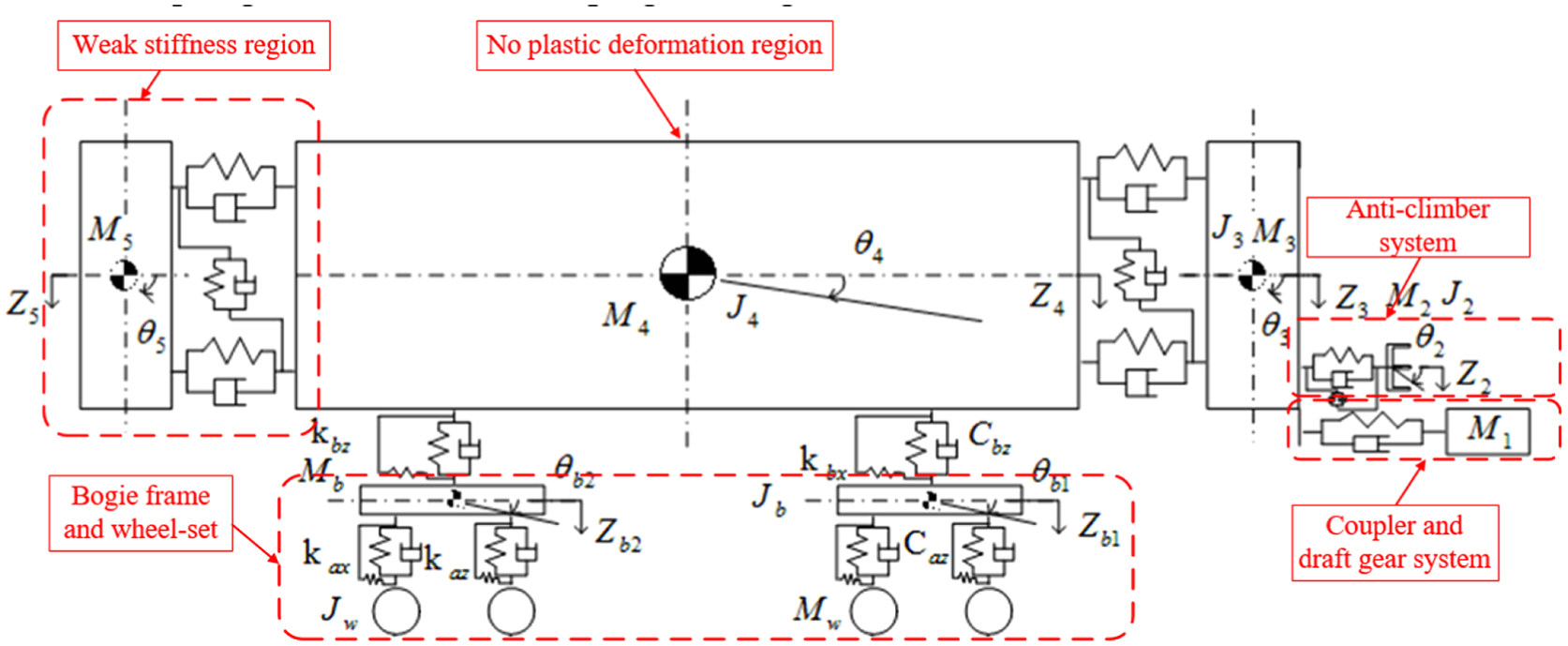
The vehicle collision dynamic model.
The concept of the substructure method is introduced, the stiffness and damping of each substructure in the vehicle model are extracted and integrated into the entire vehicle collision model, and then the differential equations are established to solve for the train collision behavior.
The coupler and draft gear model
The physical structure and a mechanical model of the coupler and draft gear between adjacent vehicles are shown in Figure 5. The diagram includes the installing seat, the buffer case, the collapse tube case, and the coupler head, and the four of the structures are considered rigid bodies with their own weight ignored. In addition, the model also includes one spherical joint, two nonlinear torsion spring units to simulate vertical and transverse oscillations, and two nonlinear hysteresis units to simulate the characteristics of the buffer and the collapse tube.

The physical structure and mechanical model of the coupler and draft gear.
The resistance force of the coupler changes with the rate of change,
where
The anti-climber model
To reduce the impact of numerical shocks caused by longitudinal impact in the simulation process, the typical resistance–deformation characteristic curve of the anti-climber is simplified as the equivalent curve, as shown in Figure 6(a) by the dotted line. The simplified curve is equivalent to the original curve in terms of energy absorption, and the properties can be reflected by nonlinear stiffness, damping, and friction pairs. The mechanical model of the anti-climber is shown in Figure 6(b).

Characteristic curve of anti-climber and its mechanical model.
Considering the influence of the initial collision speed factor, the interface force can be expressed as follows

where
The vehicle subsystem
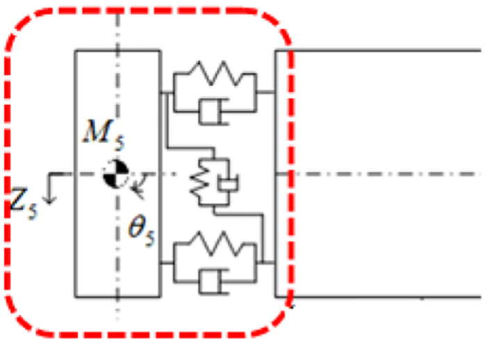
The carbody is divided into three parts, as shown in Figure 7. Figure 8 is a schematic diagram of the weak stiffness region at the vehicle end. To reflect the energy absorption characteristics of the vehicle end and the actual movement behavior during collision, the weak stiffness region at the vehicle end is simplified to a rigid mass connected by a nonlinear spring and damping unit. The model is shown in Figure 9.

The vehicle subsystem model.
Schematic diagram of the weak stiffness region at the vehicle end.
Longitudinal simplification model of weak stiffness region at the vehicle end.
Similar to the simulation of the anti-climber device, the force and displacement curve of the weak stiffness region at the vehicle end can be obtained by experiment or simulation. Due to the cost and time required for a vehicle end collision test and other uncertainties, such destructive testing is generally avoided; thus, we obtain this information by finite element simulation.
In this article, the loading curve of the vehicle is simplified to four stages, and for the unloading curve, it can be divided into two stages. The changed law of the whole structure is similar to that of the material constitutive model. The size of the concrete value can be obtained according to the actual structural performance and the finite element technique. The typical force and displacement characteristic curve of the vehicle end is shown in Figure 10. The interface force and displacement curve of the vehicle end can be defined as follows
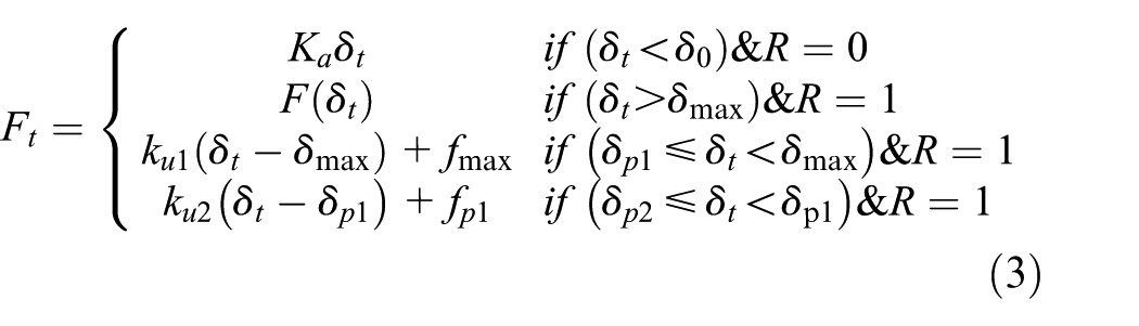
where

The typical force and displacement characteristic curve of the vehicle end.
The wheel/rail subsystem
The wheel–rail relationship subsystem is a link between the vehicle subsystem and the track subsystem, since this article only studies the case of collision in the longitudinal–vertical plane case, the vertical force of the wheel and rail is defined as follows 11

where
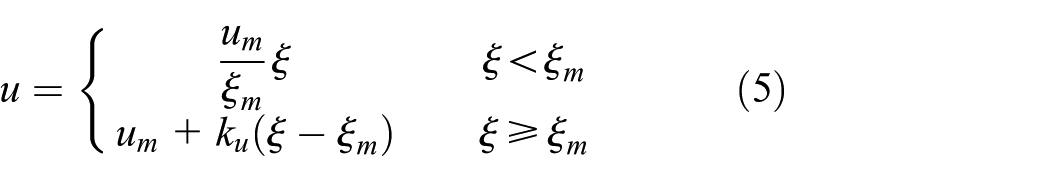
In the case of a collision, the wheel and rail are in a large creep state, according to the experimental study of Jin 13 , and the stick-slip curve is defined as follows
where
The track subsystem
The track subsystem includes the rails, sleeper, and roadbed, and each is connected by discrete springs and damping units. To obtain a greater range of frequencies, the rail is regarded as a Timoshenko beam with shear effects and rotational moments, and only the vertical vibration is considered. 11 The kinetic equation of the track subsystem can be expressed as follows

where
Train collision dynamics model
According to the analysis of each subsystem model, all the vehicles are grouped in the train. Through the coupling effect of the coupler buffer/anti-climber subsystem and the wheel/rail subsystem, the entire TCDCM is established, and its dynamic equation can be expressed as follows

where
Due to the many highly nonlinear factors in the collision dynamics equation of the train, and it is more difficult to solve equation (7) once for all. Therefore, equation (7) is divided into three equations which express

After determining the initial state of the train, according to equation (8), the same type of subsystem will be solved by display integral 14 using the “loop variable method.” 15 Then, the collision response of the entire train system is obtained. The TCDCM model calculation process is shown in Figure 11.

The TCDCM model calculation process.
Numerical simulation verification of the TCDCM model
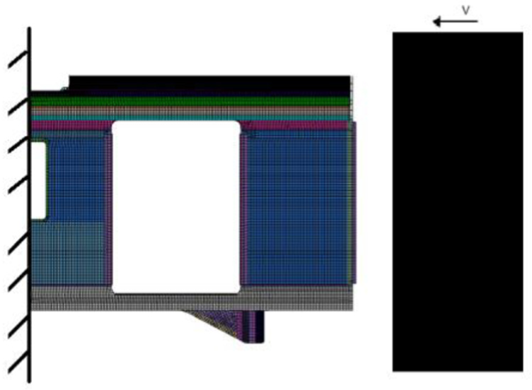
To verify the accuracy and reliability of the TCDCM model, a dynamic collision model of a certain vehicle is established, and its detailed finite element model (FEM) is shown in Figure 12. The simulation considers two identical vehicles that crashed into each other at a speed of 25 km/h. The FEM contains 1096806 nodes and 1279470 elements, and the whole calculation process is completed in LS-DYNA software (The calculation result is referred to as FEM in the following paper). Using the programmed program based on the TCDCM model in section “Train collision dynamics model,” the results from FEM and TCDCM are compared and analyzed.

The TCDCM and FEM.
Figure 13(a)–(d) shows the response comparison of the key parts of the speed, displacement, deformation, and interface forces from the FEM and the TCDCM.

The collision responses comparison of the TCDCM and FEM: (a) longitudinal velocity of the key components, (b) vertical displacement of the key components, (c) deformation of the key components, and (d) contact interface forces between vehicles.
From the above analysis and comparison, it can be found that:
From Figure 13(a), after the coupler was cut, the anti-climbers were in contact with each other at 0.05 s, as the two models of the speed curve almost coincide and then the vehicle rebounded at a velocity of −9 km/h at 0.15 s. The vehicle gradually slows down due to the friction between the wheel and rail, finally.
From Figure 13(b), the vertical response of the bogie is different in phase, which is mainly due to the local elastic vibration of the FEM. The deformation mode of the traction beam and the body bolster is closely related to the response of the bogie, but the peak values of the two methods are closer.
From Figure 13(c), the deformation diagram of the anti-climber in the two models reaches the maximum stroke of 300 mm at the same time in the time domain.
From Figure 13(d), the relative time of the interface forces between vehicles and the deformation of the end vehicle is consistent with FEM results. When the vehicle collides, the coupler absorbs the energy first until it reaches its energy absorption capacity. The resistance of the coupler increases rapidly and reaches 911 kN, and then the coupler is cut at this time. The anti-climber can continue to absorb energy in a steady and controlled way, until it reaches saturation. The end of the carbody absorbs the impact energy through the plastic deformation of the structure. The maximum interface force of the TCDCM is 4500 kN, and the maximum interface force of the FEM is 4900 kN. The error of peak value of the TCDCM and FEM is approximately 8%. The interface force and deformation curve mainly reflects the ability of the energy absorption area to absorb the impact energy. It can be seen that the TCDCM can better reflect the energy absorption capacity of the actual structure of the vehicle.
From the perspective of speed, displacement, deformation, and interface force, the simulation results of the TCDCM can be consistent with the FE simulation results, demonstrating that it is feasible to apply the TCDCM model to study the collision instability response. In addition, the FE simulation model takes approximately 15 h 20 min to run the whole simulation process, while the calculation time of the TCDCM is just 4 min 30 s. Therefore, the computational efficiency is greatly improved using the TCDCM.
Conclusion
A longitudinal–vertical plane dynamic model for train collision is developed using the multibody dynamics approach. From the research presented in this article, we can see the following:
The results of the TCDCM solution are comparable with the FEM in terms of velocity, deformation, and energy absorption. The response of the key components in the time domain is in good agreement with each other, and the error of the peak collision force peak is approximately 8%. The verification results show that the TCDCM has good accuracy with the simulation results.
The established TCDCM has obvious advantages over the FEM in terms of the calculation time, providing an effective and feasible method for the verification and design of a crashworthy structure.
The study of train operation safety in the case of a collision is a very complicated subject involving many factors. The TCDCM established in this article is proposed under the assumption of plane collision, which can only analyze the instability phenomena such as crawler and jump rails caused by train collision, and cannot reflect the horizontal response relationship when the vehicle collides with each other.
Future work will focus on improving the coupling model during the application. The 3D coupling model, considering the traverse collision will be established to explore the failure mechanism and operation safety of the train under the complicated boundary conditions.
Footnotes
Acknowledgements
The authors gratefully acknowledge National Natural Science Foundation, the National Key Research and Development Program of China, and independent research project of TPL.
Handling Editor: Jianjun Zhang
Declaration of conflicting interests
The author(s) declared no potential conflicts of interest with respect to the research, authorship, and/or publication of this article.
Funding
The author(s) disclosed receipt of the following financial support for the research, authorship, and/or publication of this article: This study was supported by the National Natural Science Foundation of China (51505390 and 51675446), the National Key Research and Development Program of China (2016YFB1200404), and independent research project of TPL (2017TPL-Z1).