
Abstract
The present study deals with the performance characteristics of a ball valve used for gas pipelines by introducing nondimensional parameters. The ball valve has relatively complex flow characteristics on the inside and downstream of the valve, although it has a simple structure as compared with the other valves. The nondimensional parameters, which define the valve operating conditions, are introduced to analyze the nature of the physical properties due to the valve’s complex flow. To define the valve flow conditions with respect to valve size, seven nondimensional parameters were selected: pressure ratio, volumetric flow rate ratio, mass flow rate ratio, Reynolds number, Mach number, valve flow coefficient, and inherent flow coefficient. The open-loop type experimental setup is designed to measure the pressure drop and the volumetric flow rate of the ball valve according to the opening rate (angle) of the test valve. Based on the experimental data, obtained by the data acquisition system of the test rig, useful nondimensional parameters to define the nature of the valve performance have been selected and determined. Throughout the experimental analysis of the ball valve, it was found that the nondimensional parameters of pressure ratio, Reynolds number, and Mach number have a similar tendency as related to the valve performance. It can be seen that the intrinsic characteristics of the ball valve are represented by the selected nondimensional parameters, which are defined irrespective of the valve size. The authors proposed a quadratic polynomial for the volumetric flow rate ratio, and the mass flow rate ratio, and introduced the formula for predicting the inherent flow coefficient by the cubic approximation polynomial. It is noted that the nondimensional parameters of the ball valve can be used to determine the performance characteristics with respect to the valve-opening rate and size effectively.
Keywords
Introduction
The ball valve is one of the essential components of a gas pipeline to shut off the gas supply or to control the flow rate. The ball valve has many advantages over other valves in its simple structure, the lowest flow resistance, and the higher closure performance. Because of these benefits, numerous long-distance natural gas pipelines have been employing the ball valve when considering the safety and pressure losses of the pipelines.
The ball valve is mainly comprised of four components: a ball, a ball body, a seat ring, and a stem. In addition, a gearbox and an actuator are needed to operate the ball valve. A ball having a spherical shape rotates up to 90°, and having the same inner diameter as the inside diameter of the pipeline under the maximum opening condition. The ball valve also has good closure performance at high pressure. Therefore, the ball valve has been widely used in various industrial fields, such as the aerospace, transportation, plant, building, water, oil, and gas industries. Many researchers have carried out numerical and experimental studies on the ball valve to investigate the flow characteristics and to ensure safety.
Moujaes and Jagan 1 performed a numerical analysis to evaluate the loss coefficient of the ball valve when it has an opening angle between 44° and 90 . Chern et al. 2 discussed an occurrence of a cavitation phenomenon at the flow pass in the ball valve by using the particle tracking flow visualization method. Chern and Wang 3 studied the effect of a V-type port installed downstream of the ball valve. They showed the possibility of a linear control of flow rate, with respect to the opening degree. Lee and Jang 4 analyzed the internal flow of the ball valve by employing a numerical simulation using ANSYS CFX, and compared pressure drops with the experimental results quantitatively. They also performed an investigation of internal flow characteristics, including the separation flow according to opening angles. Kim et al. 5 evaluated the internal flow of the ball valve using an experimental study, and proposed an approximate polynomial equation, utilizing the results of the valve flow coefficient and the pressure drop. Kim et al. 6 verified the numerical simulation model by using SC/Tetra. They used the results of the pressure drop, the valve flow coefficient, and the valve loss coefficient for the verification of the model.
As for the studies on the safety of the ball valve, Kim et al. 7 conducted an evaluation of the structural safety of a retainer type ball valve that is used for district heating, based on ISO standard criteria. They presented the safety evaluation method of a ball valve, which was numerically analyzed by using ANSYS Workbench. Kim et al. 8 assessed the leakage of a 30-in. ball valve by using an experiment, as well as proposing an empirical equation to predict the leakage of a 42-in. ball valve.
In other type studies, Huang and Kim 9 have studied the flow characteristics of the butterfly valve by introducing flow coefficient and loss coefficient according to opening angles using a three-dimensional numerical simulation. Kimura et al.10,11 discussed the characteristics of the pressure drop and the torque coefficient for a butterfly valve, according to the disk geometries. Kim and Yoon 12 studied the flow characteristics of various eccentric butterfly valves in an experimental study, based on the international standard IEC 60534-2-3. They showed the internal flow characteristics with respect to the flow coefficient and valve loss coefficient to the changing of the volumetric flow rate. Song and Park 13 have studied a method of performance evaluation for large butterfly valves by using flow coefficient and hydrodynamic coefficient obtained by the numerical analysis. Sun et al. 14 showed high-quality results to predicting the flow coefficient, based on a numerical model, when considering the effect of surface roughness. Zhou et al. 15 have evaluated the accuracy of a numerical simulation for the performance of DN500 butterfly valve by comparing experimental and numerical results of flow coefficient and pressure drop.
Despite a great deal of research with related to flow characteristics of valves, the experimental studies using nondimensional parameters are very few in number. Furthermore, only a few of the nondimensional parameters of valves that presents performance characteristics have been used, such as the flow coefficient, the loss coefficient, and the torque coefficient.
In the present study, the performance characteristics of a ball valve used for gas pipelines was assessed by introducing various nondimensional parameters: pressure ratio, volumetric flow rate ratio, mass flow rate ratio, Reynolds number, Mach number, valve flow coefficient, and inherent flow coefficient. These parameters can be used to evaluate the inherent physical characteristics in the ball valve under flow conditions, regardless of the valve size. A formula for predicting the inherent flow coefficient by the cubic approximation polynomial is proposed. It is noted that nondimensional parameters of the ball valve can be used to determine the performance characteristics, with respect to the valve-opening rate (VOR) and size effectively.
Experimental method
Experimental test rig
Figure 1 shows an experimental setup, which is an open-loop type facility, having a long circular duct. The composition of the experimental setup was based on IEC 60534-2-3 16 that was previously mentioned by Kim et al. 5 and Kim and Yoon. 12 It mainly consists of a pipeline, a valve, measurement sensors, and a data acquisition system. The inner diameter of the pipeline is 1 in., and the 1-in. valve having a trunnion type is introduced. Considering the high-pressure variations, due to the opening process of the valve, high-precision pressure transmitters, an RTD (resistance temperature detector) sensor, and an electronic flow rate meter were used. The pressures measured at the inlet and outlet positions are located at the 2D upstream and 6D downstream location with respect to the valve location, respectively. The temperature and volumetric flow rate were measured upstream of the ball valve. The data acquisition system was based on the Compact-cDAQ and LabVIEW of National Instrument Co., Ltd. It was programmed to be in control of operating the VORs and the blower rotational speeds. A regeneration blower of 2.2 kW was used to supply air to the test pipeline. The working fluid of air was used under room temperature conditions. A pneumatic actuator was used for precise ball rotation, having a maximum deviation of 0.3°.

Experimental setup: (a) Schematic diagram of experimental setup: Q (flow meter); T (temperature); P1, P2 (static pressure) and (b) picture of experimental setup.
Conditions of experiments
Table 1 presents the conditions of the experiments. In this table, the VOR corresponds to the ratio of the opening angle. That is, when the valve-opening angle is 100%, the valve is fully opened. Under these conditions, the opening angle is 90°. In the present experiments, four types of opening angle conditions, 30%, 50%, 70% and 100%, were determined to be tested through preliminary experiments. At the open angle of 90°, which is the highest flow rate condition, the blower has the maximum rotational speed, and the motor inverter frequency at this time is 60 Hz.
Experimental conditions.

Nondimensional parameters
Pressure ratio
The pressure ratio represents the relative ratio of the upstream and downstream pressures of the ball valve. The pressure ratio of over 1.0 signifies a pressure drop between the upstream and the downstream locations of the ball valve. The pressure ratio is proportional to the velocity of the working fluid in the pipeline. Using the pressure ratio, the flow conditions of an incompressible or compressible fluid can be understood. The pressure ratio (P r ) is defined as

where P1 is the pressure upstream, and P2 is the pressure downstream of the ball valve, respectively.
Volumetric flow rate ratio
The volumetric flow rate ratio represents the relation of volumetric flow rates between partial opening rates and the full opening rate. Generally, when the volumetric flow ratio is 1, the maximum flow rate passes through the ball valve. Therefore, the value is always less than 1. The volumetric flow rate ratio (vx) is defined as

where vp is the volumetric flow rate of the partial opening rates, and vf is the volumetric flow rate of the full opening rate, respectively.
Mass flow rate ratio
The mass flow rate ratio is similar to the volumetric flow rate, and it shows the relation of the mass flow rate of partial opening rates, as compared with the full opening rate. The mass flow rate is an important parameter in gas flow, as it considers temperature and density. In the present study, the mass flow rate was determined by the measuring data of the volumetric flow rate and the temperature with density being considered by REFPROP.
17
The mass flow rate ratio (

where
Reynolds number
The Reynolds number is a typical nondimensional parameter that shows the relation of the inertial force and the viscous force. This parameter is used to define whether to expect laminar flow or turbulent flow. It is also used to determine the dynamic similarity between two different fluids in fluid dynamics problems. In this study, the Reynolds number is presented to clarify the ranges and limits of the physical properties of the working fluid in the experimental study. The Reynolds number was calculated using the velocity determined by the pressure drop, and the density and viscosity values obtained by REFPROP. 17 The Reynolds number (Re) is defined as


where ρ is the density of working fluid, V is the velocity of working fluid, D is the diameter of the pipeline, μ is the viscosity of the working fluid, and ΔP is the pressure drop between the upstream and downstream pressures of the ball valve, respectively.
Mach number
The Mach number is a typical nondimensional parameter that shows the speed in relation the speed of sound. When the Mach number is over 1, the fluid flow is moving faster than the speed of sound, and under this condition in the pipe, a choked flow occurs. A choked flow causes a phenomenon, in which the mass flow rate no longer increases, even when the pressure in the channel is increased. Therefore, choked flow must avoid in the pipelines for safety. The Mach number can be estimated whether choked flow is occurring or not. The Mach number (Ma) is defined as

where V is the velocity of working fluid, and c is the speed of sound, respectively.
Valve flow coefficient
The valve flow coefficient is an essential nondimensional parameter that presents the overall performance of the valve. It is commonly used to determine a flow capacity at a certain VOR. This parameter can be expressed as a function of the flow rate and the pressure difference. In the present study, the valve flow coefficient (Cv) is based on an equation of IEC 60534-2-35,12,16 as follows
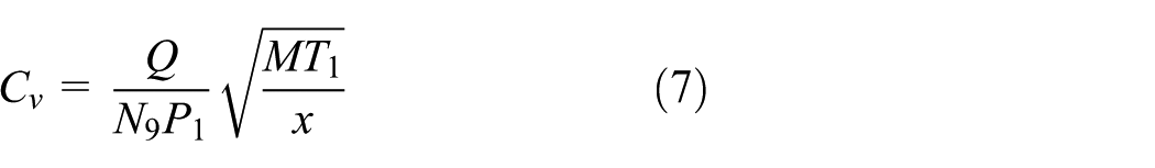
where Q is the volumetric flow rate, N9 is the formulae unit 225×101, P1 is the pressure upstream of the valve, T1 is the temperature upstream of the valve, M is the general gas constant 28.97kg / kmol, and x is the differential pressure ratio, respectively. The differential pressure ratio (x) is defined as

where Δp is the pressure drop between the upstream and the downstream pressure in respect to the ball valve.
Inherent flow coefficient
The inherent flow coefficient is useful to show the intrinsic characteristics and the performance of valves. It always has a calculated value of 1 at the full opening rate, which has maximum flow rate, where the inherent flow coefficient of certain opening rates (other than 100%) has a value between 0 and 1. The inherent flow coefficient can express with a mathematical formula using the polynomial approximation method. The inherent flow coefficient (Cx) is defined as

where Ci is the valve flow coefficient at the partial opening rate, and Cmax is the valve flow coefficient at the full opening rate, respectively.
Result and discussion
Analysis of measured data
Table 2 shows the measured data of the ball valve, with respect to rotor operating rates, and the valve-opening conditions. In this table, pressures, temperature, and volumetric flow rates are obtained by measurements while densities, mass flow rates, pressure drops, and velocities are determined by assessing the measured data.
The measuring data of a ball valve with respect to the rotational speed ratios and valve-opening rates.

From the results of the experimental measurements, the maximum volumetric flow rate of 76.03 m3/h is obtained under the blower operating condition of 3450 r/min (60 Hz), and the VOR of 100%. The maximum valve flow coefficient of 38.10 was also measured under the same conditions as the maximum volumetric flow rate. In other words, the change of volumetric flow rate has a close relationship to the passing area of the ball, while the change of the mass flow rate respects the temperature and density of the working fluid as well as the volumetric flow rate. The volumetric flow rate and the pressure drop determine the valve flow coefficient. It is noted that the volumetric flow rate, the mass flow rate, and the valve flow coefficient have a linear relation, in that they increase as the opening rate and operating conditions increase. On the other hand, the pressure drop as shown in Table 2 increases as the decrease of the opening rate and the increase of blower rotation speed. The velocity also has the similar trend as the pressure drops because of the method of calculation.
Experimental results with respect to the rotational speed ratio
Figure 2 shows the experimental results for the volumetric flow rate for the rotational speed ratio (RSR) according to each VOR. In the figure, the RSR represents the ratio of the operating rotational speed in relation to the maximum rotational speed of 3450 rpm. Thus, the RSR has a value under 1. The volumetric flow rate, concerning the RSR, has a linear relationship for all VORs. It is noted that the volumetric flow rate increases as the VOR increases.

Volumetric flow rate for rotational speed ratio according to each VOR.
Figure 3 shows the experimental results based on the pressure drop in relation to the RSR, according to each VOR. The pressure drop is defined as the difference of the pressure between the upstream and downstream locations of the valve, and is an important parameter to determine the valve flow coefficient. Pressure drop at each VOR rapidly increases due to additional working flow supplied as the RSR increases. It is noted that pressure drops in respect to the rotational speed have a nonlinear characteristic.

Pressure drop for rotational speed ratio according to each VOR.
Figure 4 shows the experimental results of the valve flow coefficient with respect to the RSR concerning each VOR. The valve flow coefficient is an important parameter to determine the performance characteristics of the valve used in the industrial field. It is obtained by measuring the volumetric flow rates and pressure drops at each VOR. The relationship between the valve flow coefficient and the RSR has the relatively nonlinear characteristic.

Valve flow coefficient for rotational speed ratio according to each valve-opening rate.
Nondimensional parameters with respect to the VOR
Figure 5 shows the pressure ratio with respect to the VOR, according to each RSR. The pressure ratio, as defined in equation (4), provides not only for the flow resistance generated in the channel, but also the information for determining whether or not a compressive flow occurs. The pressure ratio increases as the VOR decreases. If a pressure ratio is close to 1 at the VOR of 100%, the flow resistance is almost zero. The pressure ratio at the VOR of 30% and the RSR of 1.0 corresponds to 0.86. It is noted that compressive effect of the working fluid is observed where the pressure ratio has above 1.2 at the VOR of 30%.

Pressure ratio for valve-opening rate according to each RSR.
Figure 6 shows the volumetric flow rate ratio with respect to the VORs, according to the RSR. The volumetric flow rate ratio has a similar tendency according to the VOR, regardless of the RSR of the blower. If the value of the volumetric flow rate ratio is regarded as 1 under the VOR of 100%, the value 0.93 corresponds to the VOR of 70%, 0.72 at the VOR of 50%, and 0.31 at the VOR of 30%. The volumetric flow rate ratio according to the VOR can be approximated by a quadratic polynomial function formula as shown in equation (10)

where vx is the volumetric flow rate ratio, and θx is the VOR as shown in equation (11)

Here, θi is the rotation angle of the ball at each valve-opening ratio, and θ100% is the rotation angle under the full opening condition.

Volumetric flow rate ratio for valve-opening rate according to each RSR with approximation polynomial curve.
Figure 7 shows the results of the mass flow rate ratio with respect to the VOR, according to each RSR. The mass flow rate ratios have very similar values to the volumetric flow rate ratios, shown in Figure 6, when concerning the valve-opening angle, due to the incompressible flow characteristics inside the valve. The mass flow rate ratio, according to the VOR, can be approximated by a quadratic polynomial function formula as shown in equation (12)

Figures 8 and 9 show the results of Reynolds number and Mach number for the VORs, with respect to each RSR. The value of Reynolds number in the present ball valve experiments is in the range of 16,000 and 260,000. The Reynolds number inside the ball valve increases as the VOR decreases, which is due to the increase in the flow velocity, caused by the increase of the valve pressure drop. The Mach number shows similar characteristics according to the valve-opening angle as the Reynolds number, as shown in the figures.

Mass flow rate ratio for valve-opening rate according to RSR with approximation polynomial curve.
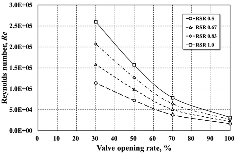
Reynolds number for valve-opening rate according to each RSR.

Mach number for valve-opening rate according to each RSR.
Figure 10 shows the valve flow coefficient for VORs, according to each RSR. As shown in equation (7), the volumetric flow rate and the pressure drop are important parameters because of their effect on the valve flow coefficient. It is noted that the value of the valve flow coefficient has been constant due to the inversed relation between the volumetric flow rate and the pressure drop. As shown in the figure, it can be seen that the valve flow coefficient has the same value, regardless of the blower rotational speed at the valve-opening angles between 30% and 70%. On the other hand, valve flow coefficient shows a slight difference from the blower rotational speed when the valve-opening angle is 70% or more.

Valve flow coefficient for valve-opening rate according to each RSR.
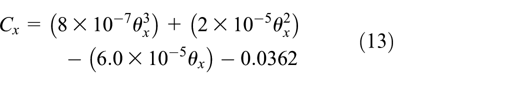
Figure 11 shows the inherent flow coefficient for VORs, according to each RSR. As shown in the figure, the characteristics curve of the inherent flow coefficient can obviously show the inherent performance of ball valve for each of the VORs, even with changing inlet conditions. The performance of industrial valves, such as the ball valve can be determined by the analyzing the inherent characteristics by introducing the nondimensional parameters, regardless of size, because the inherent flow coefficient has the value of 1 when the VOR is set at 100%. Therefore, we proposed a polynomial approximation equation for the inherent flow coefficient as shown in equation (13), and it shows to be a cubic polynomial, similar to the predictive empirical equation presented by Kim et al. 5

Inherent flow coefficient for valve-opening rate according to each RSR with approximation polynomial curve.
Table 3 summarizes the numerical data of the ball valve expressed by nondimensional parameters as mentioned above.
The nondimensional parameters of a ball valve with respect to the rotational speed ratios and valve-opening rates.

Conclusion
In the present study, the performance characteristics of ball valves used for gas pipelines have been analyzed by introducing nondimensional parameters obtained by experimental measurements. The performance data of ball valves are measured with respect to blower rotational speeds and VORs. Pressure ratios, volumetric flow rate ratios, mass flow rate ratios, Reynolds numbers, Mach numbers, valve flow coefficients, and inherent flow coefficients are introduced as nondimensional parameters. The performance of the ball valve is analyzed using the above seven nondimensional parameters and the results are summarized as follows.
The pressure ratio of the ball valve increases as the VOR decreases. It also increases nonlinearly as the RSR increases. The volumetric flow rate ratio and mass flow rate ratio have a similar tendency according to the VOR, regardless of the RSR of the blower. It is noted that nondimensional parameter presents in the form of a quadratic polynomial approximation.
The Reynolds number and the Mach number have linear trends with the RSR of the blower, and have nonlinear relations with the VOR. The valve flow coefficient and the inherent flow coefficient have similar trends, regardless of the rotational speed of the blower. The inherent flow coefficient can be presented by the formula having a cubic approximation polynomial.
Throughout the present study, the flow characteristics of the ball valve can be presented using nondimensional parameters, which can quantitatively verify the flow characteristics of the ball valves of various sizes. If the cubic approximation polynomial derived from the nondimensional parameter of the inherent flow coefficient is introduced, the flow characteristics of a ball valve having various diameters in the range of similar Reynolds number and Mach numbers can be predicted effectively.
Footnotes
Appendix 1
Handling Editor: Yong Chen
Declaration of conflicting interests
The author(s) declared no potential conflicts of interest with respect to the research, authorship, and/or publication of this article.
Funding
The author(s) disclosed receipt of the following financial support for the research, authorship, and/or publication of this article: this work was supported by a grant (13IFIP-B06700801) from Industrial Facilities & Infrastructure Research Program funded by the Ministry of Land, Infrastructure, and Transport of Korea government.