
Abstract
Thrust disk as auxiliary impeller has a vital effect on the big power pump unit with wet motor. It can balance the axial force of the unit, provide power for internal cooling circulation circuit of motor, and further reduce the axial length of the unit. Due to the motor chamber space is limited, and the transmission medium is liquid which needs to consider the effect of cavitation, the research of thrust disk of auxiliary impeller is different from the previous studies of rotating channel. In this paper, the hydraulic performance and cavitation characteristics of thrust disk as auxiliary impeller are investigated experimentally under different conditions. A thrust disk test rig was established to obtain data under different rotation speeds and flow points. Three types of volutes with different outlet angles were designed to match the thrust disk as auxiliary impeller in experiments. Results indicate that the law of speed proportion for the traditional centrifugal pump is not applicable to the head of thrust disk as auxiliary impeller. In addition, the flow coverage increases slightly with rotation speed. Furthermore, the higher the speed is, the larger the NPSHs is, and the narrower the range of NPSH is. Besides, the smaller the outlet angle is, the higher the head of the thrust disk as auxiliary impeller is, the worse anti-cavitation performance is. The research could provide reference and guidance for the design of thrust disk as auxiliary impeller.
Keywords
Introduction
Rotating channel is the foundation of researching the effect of Coriolis and centrifugal force on turbulent flow in rotating system.1,2 Johnston et al. 3 found the rotational asymmetry effect and the large-scale vortex structure in experiment for the first time. Based on the experimental results, Nakabayashi and Kitoh 4 discussed the influence of rotation on the Reynolds shear stress transport equation further. Mårtensson et al. 5 obtained the effect of rotation on the suitable scalings of pressure drop in the duct. Visscher and Andersson 6 found the length of the primary separation bubble decreases monotonically with the rise of rotation using PIV. Li et al. 7 investigated the effect of rotation on the turbulent boundary layer flow using hotwire in a rotating rig with a vertical axis and pointed out that the flow near the leading side tends to turn into laminar under the effect of rotation.
In recent years, with the rapid development of CFD (Computational Fluid Dynamics), more and more scholars used numerical simulation method to study the fluid movement in rotating channel. Niu et al. 8 proposed a modified anisotropic k–ω model considering turbulence pulsation and predicted the flow and heat transfer characteristics of the rotating channel. Pagalthivarthi and Ramanathan 9 proposed a new governing equation and deforming mesh method to solve the free surface flow in rotating channel. Mehdizadeh and Oberlack 10 observed that the both laminar and turbulent flow states have close relationship with the rotation based on direct number simulation (DNS). Munawar et al. 11 normalized the governing equations base on suitable similarity transformations for the three-dimensional squeezing flow in rotating channel. Armellini et al. 12 investigated the flow filed distribution in turbine trailing edge cooling channel under rotating condition with respect to both Reynolds with 2000 and Rotation with 0.023. Alkishriwi et al. 13 analyzed the three-dimensional structures base on large eddy simulation method, and confirmed the development of secondary flow is correlated to the rotation speed. Jiang et al. 14 investigated a fully developed spanwise rotating turbulent channel flow and found dynamic wall adapting local eddy viscosity model can get reliable mean velocity profile in high rotating case. Wang et al. 15 observed that the widthwise rib gap is favorable in reducing pressure drop under the influence of various discrete rib configurations for rotating rectangular straight channel. Wu et al. 16 acquired the dispersive stresses are associated with the flow passage among roughness elements in rotating channel using DNS.
The conveying medium in the thrust disk as auxiliary impeller is liquid in the actual working condition. The working principle is similar to that of centrifugal pump. The rotation speed, impeller, and volute all have very important influences on the performance of centrifugal pump.17–19 Also, it is necessary to take into account the cavitation.20,21 Cavitation affects the hydraulic performance, causes strong vibration and equipment damage in serious cases. 22
In general, there have been many studies on the flow characteristics for gas in rotating channels, while the research on the internal medium is liquid and according to the internal working conditions of the motor is relatively few. The object of the paper is to investigate the performance of the thrust disk as auxiliary impeller and the influence of volute on it. Therefore, the research of this paper is of great significance to the design of thrust disk as auxiliary impeller and the mechanism research of flow characteristics in the rotating channel.
The structure of high speed rescue pump
For the requirements of rapid rescue of mine flooding accident, a high speed rescue pump with wet motor was designed. Figure 1 is the assembly drawing of the high speed rescue pump, view “I” is the partial enlarged drawing of thrust disk and thrust bearing. In Figure 1, it could be seen that the thrust disk is fixed on the shaft, and the thrust bearing is stationary in the motor chamber full of cooling liquid. During the operation of the unit, with the rotation of the shaft, the water film in the wedge gap between the thrust disk and the thrust bearing is generated to balance the axial force of the pump. At the same time, in order to further reduce the length of the unit, many radial channels are drilled on the thrust disc to serve as auxiliary impeller and provide power for the internal circulation in motor.

Assembly drawing of high speed rescue pump.

Test rig.
Experiment preparation
Experiment rig
In order to obtain the hydraulic and cavitation characteristics of thrust disk as auxiliary impeller, an experiment rig was established. In the experiment rig, braided hoses are used to connect the main tank, temperature controller and tee pipe. The outlet of the temperature controller is connected with the middle port of the tee pipe. The water flows into the tee pipe from its inlet which is perpendicular to the axial direction and flows out from the outlet of the middle end cover (volute). Then, the water flows through the pipe section and finally flows back to the main tank, accordingly forming a complete closed circuit.
The top of the main tank is connected with the vacuum pump. During the cavitation test, the vacuum pump could continuously reduce the pressure at the inlet of the test section. One end of the torque sensor is connected with the main shaft through the coupling, and the other end is connected with the variable frequency high speed motor which is controlled by the frequency converter. The vertical height of the main shaft, torque sensor, and motor shaft are adjusted by the support plate to meet the requirements of coaxiality in horizontal position.
Figure 3 is the assembly structure of the main experimental section. The liquid flows into the section from the inlet of the tee pipe which is perpendicular to the main shaft, then enters the radial hole of the thrust disc with high speed rotation. Finally, the liquid flows out of the main experimental section through the outlet of volute (the middle end cover). The total distance between the thrust disc and the thrust bearing on both sides is 1 cm. The thrust bearing on both sides are fixed at the side ends of the left and right end covers respectively. The thrust disc rotates and keeps the same axial displacement with the axis. The inlet pressure sensor is installed on the tee pipe in front of the thrust disk, and the outlet pressure sensor is installed on the outlet pipe. Also, the electromagnetic flowmeter is installed near the tank to measure the flow.

Assembly of experimental section of test rig for thrust bearing.
Experimental instruments and standard
The instruments used in experiment and related parameters could be seen in Table 1.
Instruments used in experiment.

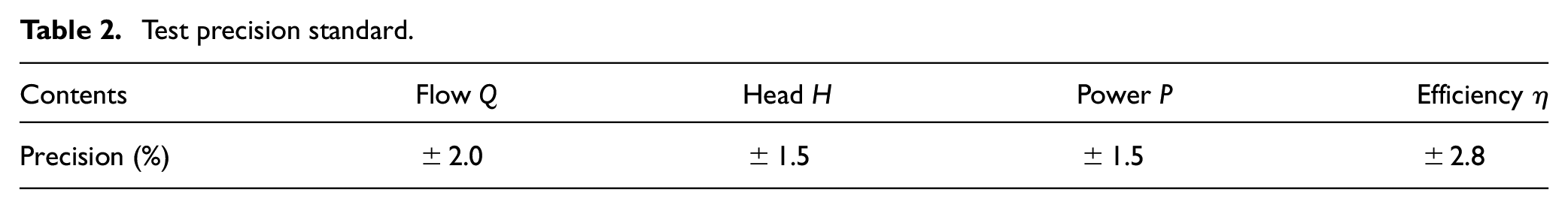
The experiment was measured according to the China B-level accuracy standard, 23 and the specific requirements are shown in Table 2.
Test precision standard.
Thrust disk and volute used in experiment
Thrust disk in experiment
The thrust disk studied is designed according to prototype in 1250 kW mine high speed rescue pump. The structure of thrust disk in experiment can be shown in Figure 4. Specifically, eight radial holes of inner diameter with 8 mm are drilled on the thrust disc to connect the top and bottom, and the surface roughness of the thrust disc is Ra0.1.
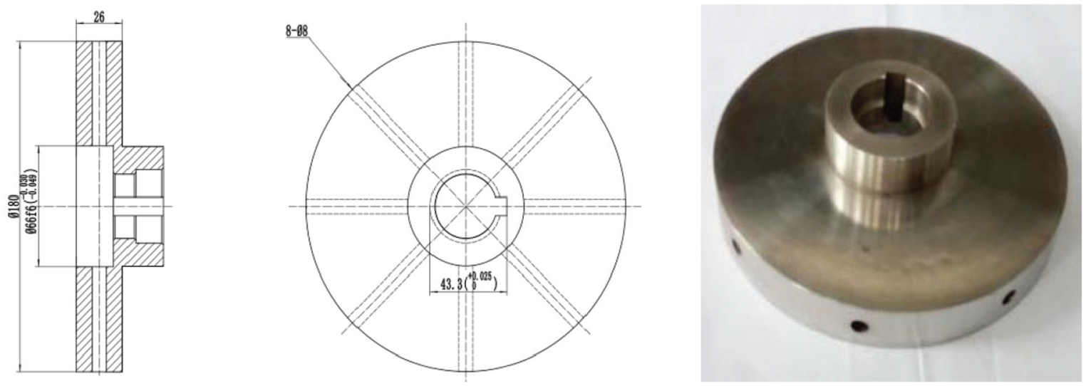
Thrust disk in the experiment.
Volute in experiment
In the actual case, the volutes matched with the thrust disk are all A volutes of outlet angle with 90° considering the axial force. However, in order to study the hydraulic characteristics more comprehensively and systematically, three types of volutes with different outlet angles are used in the experiment. In Figure 5, the outlet angles (φ0) are 90°, 45°, and 0°, corresponding to A, B, and C respectively. And the outlet angle is defined as the angle between a connection line and the horizontal axis of the base circle. The connection line connects the intersection of outlet pipe edge and base circle origin.

Volute in the experiment.
Experiment methods
The hydraulic performance test steps of each flow condition are as follows: (1) Zero calibration of the sensor; (2) Controlling the motor by frequency converter to reach the required speed; (3) Adjusting the flow by the throttle valve from 1 m3/h to each speed, and the flow increase value is 1 m3/h for each data acquisition. The maximum flow is defined as that the flow is no longer changed with the variation of speed regulating valve; (4) Controlling the temperature controller to set the fluid temperature required by the experiment; (5) Collecting the data; (6) Adjusting the working conditions and repeating the above steps until the flow point collection of all working conditions is completed; (7) Finish.
In the cavitation performance test, the first four steps are as the same as that in hydraulic performance. However, the next steps are as follows: (5) Depressurizing the main tank using the vacuum pump; (6) Collecting data; (7) Stopping the vacuum pump and restoring the flow when the head of thrust disk drops to the specified value; (8) Repeating the above steps until the experimental data collection of all operating points is completed; (9) Finish.
Experiment results
Hydraulic performance
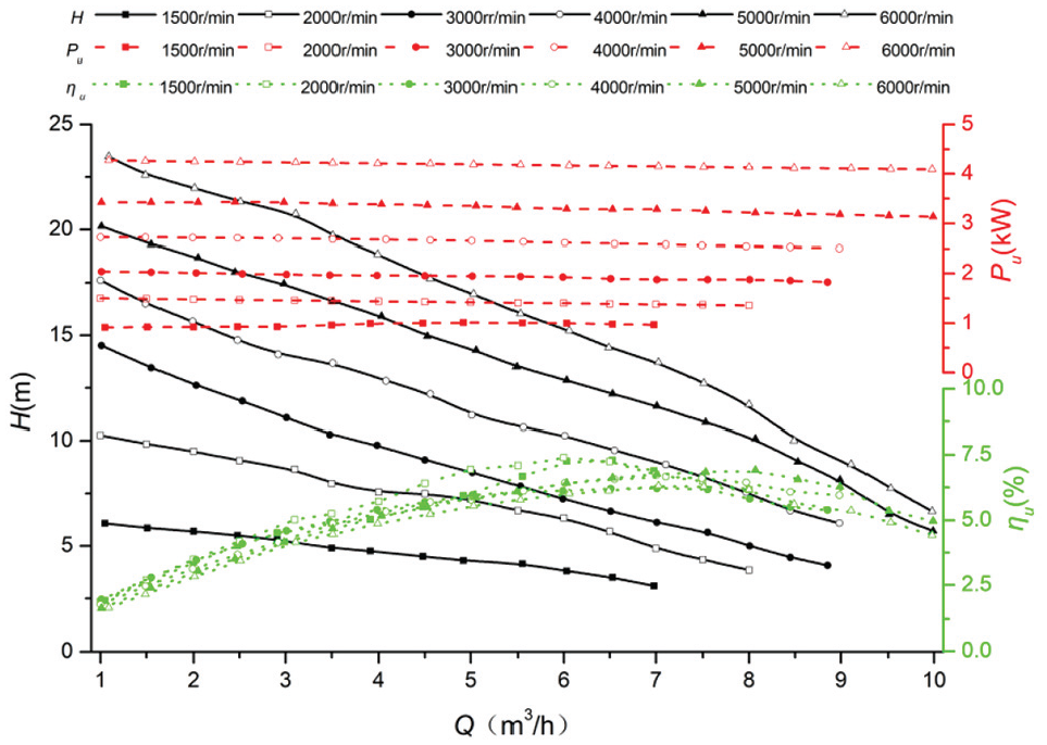
Figures 6 to 8 are hydraulic performances of thrust disk with three types of volutes that worked at 1500, 2000, 3000, 4000, 5000, and 6000 rpm respectively. Taking A volute as an example, at each speed, with the increase of flow, the head decreases continuously, the unit efficiency curve increases first and then decreases, and the power decreases slowly. With the increase of rotation speed, the flow coverage of thrust disk slightly increases; at the same flow point, the head and power also improve.

Hydraulic performance of thrust disk with A volute.
Hydraulic performance of thrust disk with B volute.

Hydraulic performance of thrust disk with C volute.
It can be seen that the decline slope of the head curve is basically consistent with the rise of flow. Different from traditional centrifugal pump, the law of speed proportion is not applicable to the head of the thrust disk as auxiliary impeller. Also, it can be inferred that there is the following relationship between the head and the peripheral velocity u2 at the outer diameter of the thrust disk:

Where, λh is the head coefficient. From the experimental results, the higher the rotation speed is, the smaller the head coefficient is. The reduction of the head coefficient may be caused by the following reasons: the peripheral speed of the water near the shaft increases with the rotation speed, resulting in the instability of the inlet flow. Besides, the unsteady flow becomes more obvious with the rotation in the radial hole of the thrust disk. In addition, the circumferential velocity at the outlet of thrust disk increases sharply with rotation speed, which leads to the bigger of water energy loss in the middle gap between thrust disk and thrust bearing pad.
Also, the effective flow range increases slightly with the rotation speed. This phenomenon shows that the flow range of the thrust disk is related to its own structural characteristics. Different from the traditional centrifugal pump, the flow range has no obvious relationship with the speed. Furthermore, it can be inferred that the number and radius of the radial holes of the thrust disk determine the flow area under a certain working condition, thus affecting the flow range.
As shown in these figures, the unit efficiency is relatively low at each stage of speed, and the maximum unit efficiency under all working conditions is 6.5%, the maximum unit efficiency is only 6% at 6000 rpm. The reasons for low unit efficiency are as follows:
unit efficiency ηu is determined by

Where, ηh is hydraulic efficiency, ηv is volumetric efficiency, and ηm is mechanical efficiency.
In terms of hydraulic efficiency, the outlet position of the volute is at the top of the base circle, the high speed liquid is thrown out by the radial hole of the thrust disk is not at the tangential position, resulting in large hydraulic loss because of the disorder of the flow at the gap between the thrust disk and the volute. In addition, the instability of the inflow at the inlet and the flow characteristics in the radial hole of the thrust disk mentioned above are also important reasons for the low hydraulic efficiency.
In terms of mechanical efficiency, the length of the main shaft of the experiment rig is long, and one end of the shaft is connected with the axial force test device by fasteners. Considering the mechanical loss caused by the components of the experiment rig, such as the mechanical seal, framework oil seal and the transmission of coupling, the whole mechanical efficiency loss is large.
In terms of volume efficiency, in order to protect the core components of the experiment rig, three cooling circulation circuits are equipped to cool and lubricate the relevant components; furthermore, there is a gap between the thrust disk and the thrust bearing. Combined with the two above factors, the volume efficiency is also relatively low. Based on the above reasons, the hydraulic efficiency, volumetric efficiency and mechanical efficiency of the thrust disk are all small, resulting in low unit efficiency.
When flow Q reaches about 6 m3/h, the unit efficiency reaches the maximum value, and then decreases slowly. Under the condition of small flow, the disc loss caused by the clearance between the thrust disc and thrust bearing may account for a large proportion of the shaft power, resulting in relatively low efficiency of the unit under small flow condition. In the vicinity of 6 m3/h, compared with other flow points, the efficiency of the whole unit is the largest. Since the flow area of the radial hole in the thrust disc is constant, when the flow exceeds the optimal flow point, the flow passage may be blocked, resulting in insufficient flow and unit efficiency reduction. Also, the power curve shows a very slow downward trend with the increase of flow. Therefore, the change of flow has little effect on the power.
Comparing the three figures in Figure 9, it could be concluded that with the decrease of the outlet angle of volute, the head at each flow point increases obviously. When φ0 is 90°, 45°, or 0° respectively, the maximum head under all flow for the three angles is 19.43, 23.47, or 28.52 m. That is, the variation of outlet angle could increase maximum head by about 1.47 times.
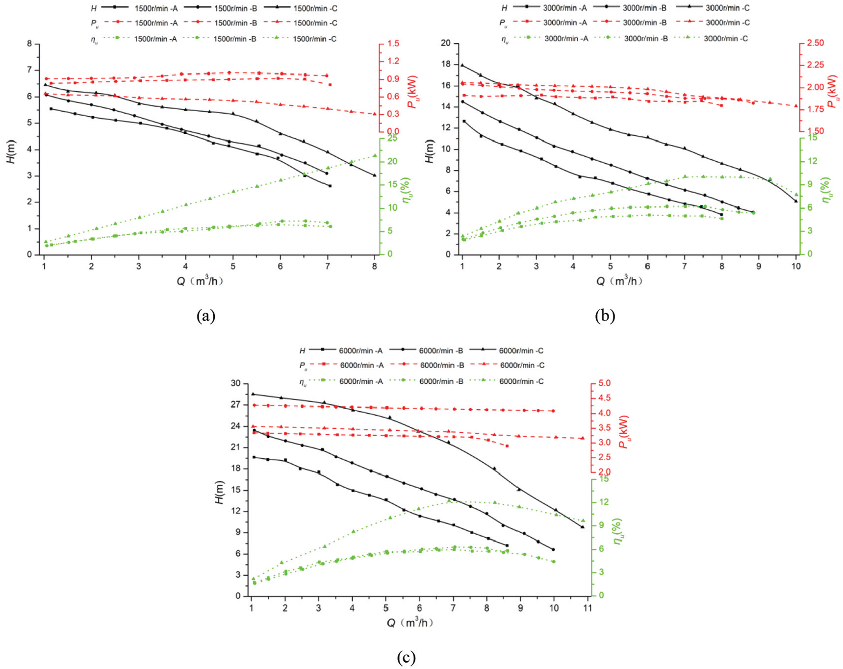
Difference of hydraulic performance of thrust disk with different volutes: (a) 1500 rpm, (b) 3000 rpm, and (c) 6000 rpm.
Table 3 is the head at partial flow points. Taking 2 m3/h as an example, the heads produced by C volute are 1.18, 1.54, and 1.45 times of A volute at three rotation speeds. When the flow is 4 m3/h, the corresponding values are 1.18, 1.81, and 1.76. When the flow is 6 m3/h, the corresponding values are 1.24, 1.93, and 2.06. The phenomenon shows that the difference of head caused by the change of outlet angle at the same flow point significantly increased with the rotation speed, which is also related to the increase of flow coverage.
Head at partial flow points.

Figure 10 is the velocity triangle at the outlet of the radial hole of the thrust disc, and the circumferential velocity u2 at the outlet is shown in equation (3),

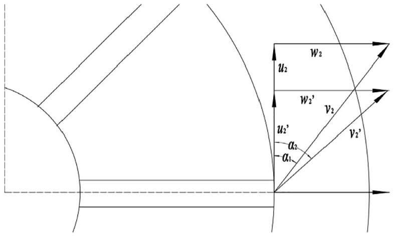
Velocity triangle at outlet of thrust disk.
Where, Dt2 is the diameter of the thrust disk, m; n is rotation speed, rpm.
When the unsteady inlet liquid flows into the radial hole of the thrust disc, it becomes more obvious and leads to greater head loss. Considering the three outlet angles of volute, with the decrease of φ0, the position of volute outlet is more and more far away from the horizontal axis, which indicates that the water thrown out from the outlet of horizontal axis needs to move longer in the clearance area. In this region, u2 must be reduced due to the possible backflow phenomenon in the gap region.
Cavitation performance
Figure 11 shows the cavitation curve of the thrust disk as auxiliary impeller with three different volutes. The three groups of data were measured at 1500, 3000, and 6000 rpm, and the flow points were 2, 4 and 6 m3/h, respectively. The curves are marked as flow-volute type (e.g. 2-A means that the cavitation curve is measured at the flow point of 2 m3/h with A volute).
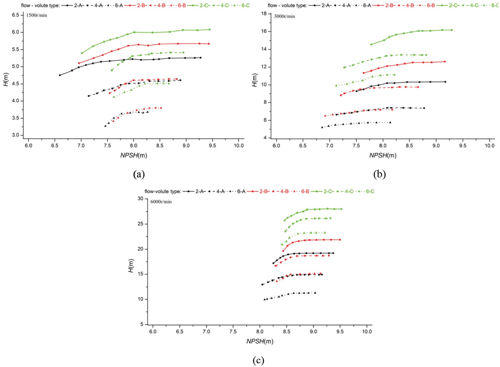
Cavitation performance of thrust disk with different volutes: (a) 1500 rpm, (b) 3000 rpm, and (c) 6000 rpm.
The abscissa in the figure is NPSH, where the number calculation formula can be expressed by:
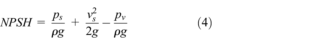
Where, Ps is inlet pressure, Pa; Pv is vapor saturation pressure, Pa; vs is inlet velocity, m/s; g is the gravitational acceleration, m/s2; ρ is density, kg/m3.
In order to analyze the cavitation phenomenon, it is stipulated as follow: when the amplitude of head drop is 10%, the experiment will stop, and the NPSH for the moment could be recorded as NPSHs.
According to the Figure 11, with the increase of rotation speed, the variation range of NPSH corresponding to stable head at each operating point decreases continuously. Also, NPSHs are also different, it may indicate that the speed has an obvious influence on the anti-cavitation of thrust disc as auxiliary impeller.
Taking 2 m3/h as an example, the higher the rotation speed is, the larger the NPSHs is, and the narrower the range of NPSH is. It indicates that the anti-cavitation performance of thrust disk as auxiliary impeller is inversely proportional to the rotation speed. At the same flow, the higher the rotation speed causes more unstable flow which could lead to impact loss and backflow when the water enters into the radial hole of thrust disc. Due to the existence of flow instability, it is easy to lead to low local pressure at the inlet. In the area, bubbles are generated and developed, which is more likely to form cavitation.
At the same time, it can be concluded that at the same temperature, the cavitation characteristics of each flow point is also different with the rotation speed. Under 1500 and 3000 rpm, the maximum of NPSHs is at 6 m3/h and the maximum is at 2 m3/h. However, under 6000 rpm, the minimum is at 6 m3/h, and the maximum is at 2 m3/h.
It can be inferred that the anti-cavitation performance of the thrust disk in small flow is better than that in large flow at medium and low speed. However, the condition occurs reversal at high rotation speed. Considering the special flow condition of the inlet, the water velocity at the inlet can be divided into axial and circumferential velocity. The higher the rotation speed is, the greater the circumferential and axial velocity are. The increase of absolute velocity composed by axial and circumferential velocity could rise the kinetic energy then reduce the pressure in inlet region. It can be inferred that: at low and medium rotation speed, the amplitude of absolute velocity and kinetic energy increases with axial velocity component, which leads to the decrease of inlet pressure. Therefore, the anti-cavitation performance under small flow rate is better than that under large flow rate. However, at high rotation speed, large impact loss occurs on the inlet wall due to circumferential velocity. In addition, the impact loss of circumferential velocity increases with the flow and axial velocity. The phenomenon could cause the decrease of absolute velocity, the increase of pressure and the enhancement of anti-cavitation performance.
Table 4 is the specific NPSHs value under various working conditions. The results show that NPSHs increases with the decrease of outlet angle φ0 at each speed and flow point. The anti-cavitation performance of A volute is better than that of B volute, and that of C volute is the worst.
NPSH s at partial flow points.

With the increase of φ0, the distance between the volute outlet and the horizontal position of the thrust disk increases. So, this part of water needs to flow from the horizontal position to the outlet to overcome the resistance. The more work the water dose, the less kinetic energy is, which leads to the increase of the pressure energy in this area.
In general, the different outlet angle has a significant impact on the hydraulic and anti-cavitation performance of the thrust disk as auxiliary impeller. With the decrease of outlet angle φ0, the hydraulic performance increases, but the anti-cavitation performance decreases.
Conclusion
In this study, a thrust disk experiment test rig was established to investigate the hydraulic and cavitation characteristics of thrust disk as auxiliary impeller. Comparisons among six rotation speeds and three volutes with different outlet angles were conducted for different flow rates.
With the increase of rotation speed, the flow coverage of thrust disk slightly increases; at the same flow point, the head and power also improve. The law of speed proportion for the traditional centrifugal pump is not applicable to the head of the thrust disk as auxiliary impeller.
The anti-cavitation performance of thrust disk as auxiliary impeller in small flow is better than that in large flow at medium and low rotation speed. The higher the rotation speed is, the larger the NPSHs is, and the narrower the range of NPSH is, which indicates that the anti-cavitation performance of thrust disk as auxiliary impeller is inversely proportional to the speed.
The smaller the outlet angle is, the higher the head of the thrust disk as auxiliary impeller is, the worse anti-cavitation performance is.
Footnotes
Handling editor: James Baldwin
Declaration of conflicting interests
The author(s) declared no potential conflicts of interest with respect to the research, authorship, and/or publication of this article.
Funding
The author(s) disclosed receipt of the following financial support for the research, authorship, and/or publication of this article: this work was partly supported by the grants of National Natural Science Foundation of China (No.51805241, 51806082), The Natural Science Foundation of the Jiangsu Higher Education Institute of China (No. 20KJB470016, 19KJD470006), Jiangsu Natural Science Foundation (No.BE2018085), The Open Research Subject of Key Laboratory of Fluid and Power Machinery(Xihua University), Ministry of Education (grant number LTDL2021-004), The Excellent Scientific and Technological Innovation Team of Jiangsu Higher Education Institutions (Intelligent Manufacturing Equipment Design and Engineering Application); Qing Lan Project, Scientific Research Foundation of Nanjing Institute of Technology (No.YKJ201933), and Science and Engineering Research Project of Wuxi Institute of Technology (No. ZK202001).