
Abstract
Deployable mechanisms in CubeSat satellites have many problems with the system that provides the anchor position. The main defect of the traditional deployment mechanisms for solar panels in CubeSats is the lack of position system to block the back-driving of the panel when it reaches the final phase of the deployment. This generates spurious oscillations in the panel, affecting the photovoltaic process as well as generating fatigue in the mechanical elements of the mechanism (hinge or pin). In this work, the design, analysis and manufacture of a deployment mechanism for CubeSat solar panels is shown. A finite element method analysis was carried out in a hinge with an integrated blocking system as well as a double torsion spring, which can be used on CubeSats. The outcome shows the layout of the described anchor hinge and the used double-torsion spring, which provides a positive direction torque transfer. Likewise, the performed numerical analyses on the designed system, reduce the weight and optimise the geometry of the mechanism, showing its feasibility as well as the potential applications and further research in the area.
Introduction
Artificial satellites in orbit around the Earth are usually classified by their weight. In this classification, nanosatellites (1–10 kg) have become important in the last decade, mainly because of their low development costs and standardised form factors. Between the numerous possible configurations for nanosatellites, the CubeSat denomination has become very much popula because it provides a standard that allows universities to integrate their own satellites; it also serves as a cost-effective platform to perform research in space sciences. Although first conceived by Heidt et al., 1 in 2009 California Polytechnic State University (CalPoly) and Stanford University presented the most accepted standard for the CubeSat specification. 2 As most satellites, CubeSats satisfy their power generation capabilities mainly by solar cells. There are two options to provide a CubeSat with electrical energy: solar cells attached to the body of the satellite and solar cells attached to a planar structure able to be deployed.
Deployable solar panels increase power generation.3,4 Anyway, the deployment of solar panels clearly changes the position of the mass centre for the whole satellite, which may help to improve, or to hinder, the stability and attitude of the satellite, depending on the design strategy of attitude determination control system (ADCS) subsystem (deployable boom). They also allow the integration of some other devices such as high-gain antennas to increase communication capabilities. 5
Mechanisms to deploy elements in satellites when in their orbital positions can generate motion through active or passive techniques. Active mechanisms require power resources to turn on mechanical elements generating deployment motions, usually through electric motors. Passive techniques do not require any electrical power resources, so they contemplate, for instance, the use of mechanical springs to provide the necessary energy for deployment. Deployment mechanisms are actuated only when in orbit.6,7
The first time that a rotatory passive mechanism was used to deploy solar panels in CubeSats was in 2002 when Stanford University employed torsional springs and hinges to deploy solar panels in the QuakeSat project.8,9 From that point, several missions have used deployable solar panels in very different configurations and with diverse deployment mechanisms.8–14 Whichever the possible solar panels arrays and the deployment mechanisms to be used, the CubeSat standard imposes strong restrictions to satellite development, particularly of weight and size, which ought to be necessarily taken into account when designing new arrays of solar panels as well as innovative mechanisms of deployment. Furthermore, despite of CubeSat standard, 2 there are several norms and procedures that specify the methodology as well as other restrictions when characterising and designing such systems. For instance, NASA 7 proposes a methodology of three phases to design mechanisms for satellites, which tends to obtain functional and low-cost designs, satisfying most restrictive standards. According to NASA, a successful deployment mechanisms ought to have four stages: initial blocking, motion release, deployment guide and final blocking. 7
Several deployment mechanisms, both active and passive, has been developed till now. Some of the most used passive mechanisms for nanosatellites are those based on coil springs, torsion springs and flexible joints (tape springs); on the side of active mechanisms, the most popular are electric motors and deployable booms. Table 1 shows the comparision between advantages and disadvantages of passive deployment methods, while Table 2 benchmarks the pros and cons of active methods. For further information, we refer the reader to Höhn. 6
Advantages and disadvantages of different passive deployment techniques. 6

ADCS: attitude determination control system.
Advantages and disadvantages of different active deployment techniques. 6

MMOD: micrometeoroid or orbital debris; SMA: shape memoy alloy.
As it is well known (and can be observed in Table 2), the main disadvantage of active mechanisms is their requirement of power to work. As CubeSats are heavily restricted, 2 effective solutions need to be implemented to perform deployment of solar panels, to increase their power catchment while no consuming power of the system, so passive mechanisms are strongly preferred.
A very common passive solution for rotatory motion are torsion springs. Although they possess ideal advantages as no power consuming, a linear mechanical behaviour, reduced volume and weight, between others (see Table 1), one of the main problems till now is that they lack final blocking phase, 7 particularly because of the size and weight restrictions in CubeSat. 6 This typical feature leads to oscillations due to the degree of freedom that each solar panel has when deployed.
Oscillations in space are a very well known problem. Most of them come from orbital features, as the eccentricity of the orbit, the orbit plane, frequency parameters, the true anomaly and moments acting in the satellite axes. 15 In other words, the satellite goes from the stable equilibrium position into stable oscillatory motions with amplitudes and periods of the order of the revolution of the orbit. 16 These natural oscillations tend to be magnified if deployable mechanisms do not possess the final blocking phase; they may introduce large disturbance torques due to larger inertia and interaction with Earth’s atmosphere and solar pressure. Thus, they place much stress into ADCS, which in turn might get saturated, being unable to counteract them, or ought to be over-dimensioned, increasing power consumption and mass which is completely undesirable in CubeSats.16,17
In order to try to solve the problem of the final blocking, lately flexible joints (tape springs or carpenter tapes) have become much popular, which are strain-energy mechanisms. These are narrow metallic strips with a curved cross-section, that works under the simple torsion spring principle.18,19 Furthermore, these elements have been proved to be useful to incorporate reflectors of solar light. 20 Nevertheless, their complexity is related to their (uncontrollable) non-linear mechanical behaviour. 21 They also must be specifically configured for their final goal for a specific space mission, 19 which hinders the manufacture process. Thus, although they are passive mechanism with a final locking, they represent design complexities.
This article deals with the lack of final blocking system for torsion spring deployment systems, that is, to endow traditional torsion spring mechanisms with a final blocking state so as to preserve their main advantages (Table 1) while helping to reduce the oscillations provoked, or increased, by deployed unlocked solar panels. This problem is addressed by proposing the design of an innovative hinge with an integrated final blocking element. The proposal highlights because no additional mechanical elements are added and minimal weight increase is performed.
Materials and methods
The conceptual and mechanical design of the deployment mechanism is shown in Figure 1. The proposed passive mechanism generates a lateral rotation motion based in an innovative anchor hinge design with a double torsional spring, to deploy the solar panels to a final position of 90° with respect to CubeSat’s body. The main hinge possesses a blocking element that acts when the panel finishes its deployment sequence until the final position, as it is shown in Figure 2(a). This blocking element has its counterpart in the secondary hinge, consisting of two latches in the borders where the pin is inserted (Figure 2(b)). Figure 2(c) and (d) shows in detail the contact surfaces between the blocking elements in each hinge, when the panel is bent in its initial position. When the panel is released from the initial position, the rotatory motion described by the secondary hinge is shown in Figure 2(e), and it occurs in such a way that the contact area between the surfaces (Figure 2(d)) reduces while the motion approaches the final position of the panel (Figure 2(f)). In this final position, the latch in the secondary hinge reaches a slot that prevents back-driving (Figure 2(g)). The pin placed at the top part of the hinge avoids the secondary hinge with the panel attached to continue the deployment trajectory (Figure 2(h)). In addition, this minimises rebounds at the end of the travel.
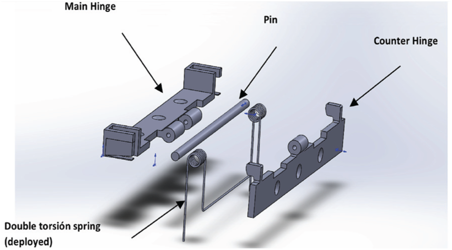
Conceptual design for the proposed mechanism.
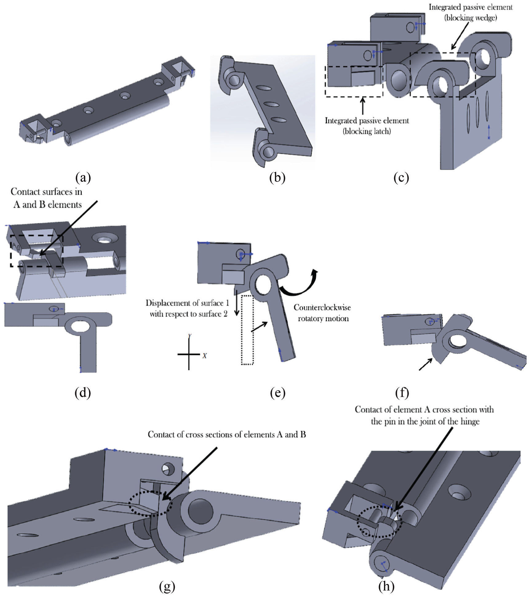
Different views of the elements of the proposed mechanism: (a) main hinge, (b) secondary hinge, (c) contact elements in the bent phase of the panel, (d) contact surfaces of the final blocking element, (e) deployment trajectory, (f) reduction of the contact area between surfaces, (g) back-driving blocking of the hinge, and (h) pin’s contact for the blocking of the deployment trajectory.
For the design of the hinge and counterhinge, aluminium 6061 was used, according to the allowed materials suggested by the CubeSat standard. 2
In order to validate numerically the presented system, the referred double torsional spring shown in Figure 1 was over-dimensioned, so to bring the hinge system under greater stresses than those during their lifetime. Actually, the spring design corresponds to the Earth’s conditions (1g), in part due to the fact that we do not possess zero-gravity facilities to perform experimental tests in accurate space conditions. The design process of the spring can be consulted in the Appendix 2.
Two study cases are considered, as follows:
The analysis of the torsional load applied by the spring over the pin.
The anchor required to avoid the oscillation of the panel in the hinge.
Those elements were modelled by computer-assisted design (CAD), and then numerically simulated by finite element method (FEM) in computer-assisted engineering (CAE) software. 22
Pin
For the boundary conditions used for the FEM analysis (Figure 3), the number of elements were 682, the number of nodes used were 3638 and the type of element used was Solid 186 with 20 nodes per element. A bonded contact condition between the internal cylinder in the hinges and the pin (Figure 3(c)) is defined. An experimental load of 2 N (as determined in the Appendix 2, with a security factor of 15%) is considered, equivalent to the weight of the solar panel in undeployed phase (Figure 3(c)) in terrestrial conditions.

Discretisation, boundary conditions and loads on pin for FEM analysis: (a) discretisation, (b) free body diagram and (c) contact surfaces.
Hinge system
For the sake of FEM analysis purposes, the hinge system was divided in hinge and counterhinge.
Hinge
For the boundary conditions used in the FEM analysis, the number of elements were 2401, the number of nodes used were 4889, and the type of element used was Solid 187 with 10 nodes per element (Figure 4(a)). For the blocking latch of the main hinge, a force

Discretisation, boundary conditions and loads on main hinge for FEM analysis: (a) discretisation, (b) force acting in the internal part of the blocking latch of the hinge, (c) active elements of the mechanism, (d) fixed support of the main hinge and(e) panel torque in X+ direction.
Counterhinge
For the boundary conditions used in the FEM analysis, the number of elements were 3291, the nodes used were 1548, and the type of element used was Solid 187 with 10 nodes per element (Figure 5(a). The surface at which a 100 N force acts upon the blocking latch of the main hinge is shown in Figure 5(b). Fixed boundary conditions are set up at the contact surface between the counterhinge and the solar panel (Figure 5(c)). The displacement restrictions on the blocking element of counterhinge are shown in Figure 5(d).
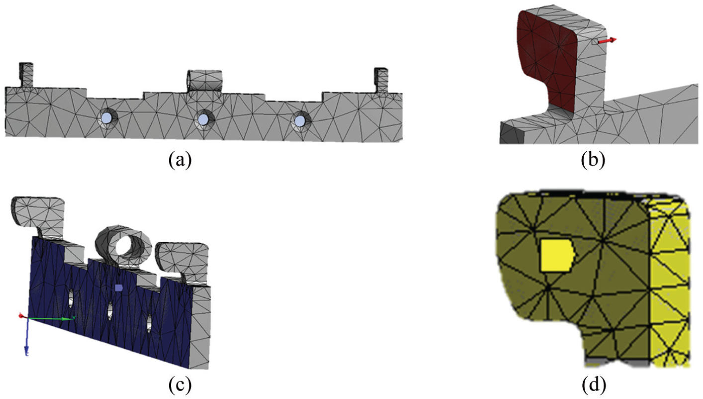
Discretisation, boundary conditions and loads on counterhinge for FEM analysis: (a) discretisation, (b) acting force in the blocking element of the counterhinge, (c) fixed support of the counterhinge and (d) displacement constraint in the blocking element of the counterhinge.
In Figure 4(c), the active elements of the hinge and counterhinge as a whole are shown. On them, a 300 N mm load corresponding to the generated momentum by the panel’s weight (Figure 4(e)) was applied.
Results
From the FEM analysis, a von-Misses stress of 1.4 MPa in the middle position of the pin due to the panel’s weight was obtained, which can be appreciated in Figure 6. This area of the pin would be particularly stressed in the launching phase of the rocket which would put the CubeSat in orbit.

FEM analysis of the pin.
Critical areas in both the main and secondary hinges, also made of 6061 aluminium, were analysed. The first critical element is the locking latch in both hinges (Figure 7). For the element in the main hinge (Figure 4(e)), a maximum von-Misses stress of 139.06 MPa (Figure 7(a)) was obtained, while for the element in the counterhinge (Figure 5(b)), a maximum von-Misses stress of 307 MPa was obtained. These are shown in Figure 7(b).

FEM analysis of the locking latches in both hinges: (a) main hinge and (b) counterhinge.
The active elements of the hinge in the final deployment phase, defining the support areas of the elements when the back-driving locking is reached (Figure 4(c)) were also analysed. A maximum von-Misses stresses of 9.7 MPa in the active element of the main hinge, as well as of 46.721 MPa in the active element of the secondary hinge were obtained. These are shown in Figure 8(a) and (b), respectively.

FEM analysis of the active elements of the hinge in the final deployment position: (a) von-Misses stress in the main hinge and (b) von-Misses stress in the secondary hinge.
Validation of the mechanism
The proposed mechanism was validated through the fabrication of a prototype of a 3U CubeSat. The manufactured spring is shown in Figure 9. For the prototype, a phenolic plate was used to simulate the solar panel with standardised weight and mass distribution. 23 The CubeSat structure was generated under the official size specification. 2 In Figure 10, the built physical prototype is shown, in a phase of the deployment. In Figure 11, the solar panel can be observed at 90° with respect to CubeSat’s body, with the hinge locked in its final position.
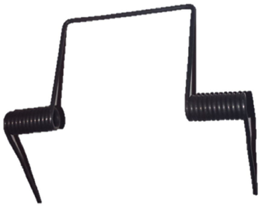
Manufactured double torsion spring.

Manufactured prototype, with the solar panel during the deployment phase.
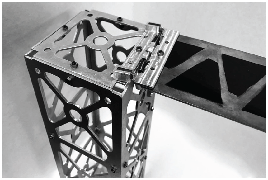
Solar panel deployed in its final (locked) position.
It ought to be noted that the manufactured spring was able to perform the rotational work to deploy the solar panel adequately in Earth conditions (1g), so the design process of the double torsional spring presented in the Appendix 2 is validated.
Discussion and final remarks
In this article – an innovative passive mechanism with an integrated final locking system, which consists of a reduced number of mechanical parts – has been proposed, constituting an excellent option to be implemented, as it follows the CubeSat philosophy.
Currently used passive deployment systems in CubeSats8–10,12,24–28 lack any element preventing the back-driving motion of deployable solar panels when deployed. The mechanism herein proposed is, at the knowledge of the authors, the first one in the literature that tackles this open problem in CubeSat solar panel deployment systems based on torsional springs.
This deployment mechanism presents a notable benefit to deploy rigid solar panels with respect to other solutions. Although all solutions require to comply with the four stages (initial blocking, motion release, deployment guide, and final blocking), current deployment mechanisms require the implementation of more than one element to fulfil those stages. The mechanism herein presented allow to comply with three of those stages (it do not possess initial blocking in its current status) without incorporating additional mechanical elements. Furthermore, the weight increment due to the latches for the final blocking mechanisms is almost negligible.
Although the proposed mechanism do not possess an initial blocking system, we propose for it to comply with the initial blocking stage a traditional burn wire release mechanism. 29 Further research is required to set the values of the optimised working parameters of this system to work with the presented hinge mechanism.
The FEM analyses performed to the spring and the hinge, show that the stresses generated on this elements during the critical phases of mechanical loads, do not overcome the yielding strength of the proposed material. Although the carried out FEM analyses were static, the considered loads values guarantee an adequate performance of the mechanism under kinematic and dynamic analyses. Furthermore, the FEM analysis was indispensable in order to optimise the size and weight of the mechanism herein proposed, which is always a strict demand in space engineering, so to obtain a system within the CubeSat standard specifications. 2
This conceptual design for the hinge is the first step in the development of a fully operational prototype in space conditions. As a future work, the dynamic analysis for deployment, considering effects such as micro-gravity, friction and realistic oscillations 30 ought to be carried out. In order to do so, we seek academic collaborators with space-oriented facilities in order to perform dynamical experimental tests.
It ought to be emphasised that the design of the double torsion spring considered the value of the gravity acceleration at sea level (9.807 m/s2). While the double torsional spring is designed in order to work properly in an Earth-based test, it is over-dimensioned for a real space application. A future work consists of taking a criterion for spring dimensioning based on the solar panel impact energy when full deployment is reached, and there is a sudden stop of the solar panel rotation, as well as on the inertial structural solicitation due to the sudden locking shock.
Although the hinge and the counterhinge were provided with three basins as customary, so to be attached to the main body and the solar panel, respectively, it is a well known fact in the literature that their size and positions affect in an important way the performance of the mechanism.4,5,11,13,28 Further research on this topic ought to be done to determine the optimum basins configuration for the mechanism proposed herein.
In brief, the advantages of this proposal are as follows: the usage of a passive deployment technique with motion guidance and final blocking; the decrease of structural weight; and that the final blocking latches in this design allows final position configurations of the deployed panels of 90°, 135° and 180°.
On the other hand, the main drawback of the hinge system is the manufacture. As the dimensions of the latching elements are very reduced, it requires very precise manufacture techniques to obtain it. Thus, fine errors in the manufacture may make the final blocking to fail. Furthermore, the bending of the panel to place it in its initial position before being deployed must be made very carefully in order to assure the correct initial position as well as the integrity of the final blocking mechanism.
As a final concluding remark, this study shows the feasibility of the deployment mechanism with the final locking system proposed herein. Nevertheless, further research on the performance of this mechanism within space conditions ought to be carried out, in order to determine its dynamical response in a constrained environment.
Footnotes
Appendix 1
Appendix 2
Acknowledgements
This paper abstracts much of the experience transmitted through postdoctoral stays between 2012 and 2013, as well as several research stays in May 2014, October 2015 and September 2016, under the supervision of Dr Luis Martínez Sáez at Universidad Politécnica de Madrid, through research projects SPIP2015-01862 y TRA2016-77979-R. Those research experiences have nowadays been consolidated through the signature of several collaboration agreements between Universidad Politécnica de Madrid and Instituto Politécnico Nacional, which has aided to the formation of highly qualified human resources as well as joint research between Spain and Mexico.
Handling Editor: Jose Ramon Serrano
Declaration of conflicting interests
The author(s) declared the following potential conflicts of interest with respect to the research, authorship, and/or publication of this article: The founding sponsors had no role in the design of the study; in the collection, analyses, or interpretation of data; in the writing of the manuscript, and in the decision to publish the results.
Funding
The author(s) disclosed receipt of the following financial support for the research, authorship, and/or publication of this article: The authors acknowledge EDI grant by SIP/IPN. This research was partially supported by projects 20181139, 20180472, 20181441, 20181028, 20181141, 20181454 and 1931, all by SIP/IPN. A.S.-S. acknowledges partial support of CONACyT, México.