
Abstract
The semi-spade rudder and KP458 propeller of the KVLCC2 (KRISO very large crude carrier) model tanker are adopted by ITTC maneuvering technical committee in the comparative study of ship maneuverability. The incompressible viscous flow around semi-spade rudder and KP458 propeller is investigated using Reynolds-averaged Navier–Stokes equations, the computational grids are generated using ICEM software, and finite volume method is employed to discretize the governing equations. Combined with turbulence model, the hydrodynamic performance of semi-spade rudder is analyzed at different rudder angles, and the result provides a reference for the estimation of the hydrodynamic characteristics of semi-spade rudder. The multi-reference framework method is employed to carry out the numerical simulation of the flow field around the propeller. The thrust and torque of propeller under different turbulence models are calculated in the simulation. The thrust coefficient curve, torque coefficient curve, and efficiency curve are present. The pressure distributions of the pressure side and suction side of propeller blades are studied at different advance coefficient. Based on the study of the hydrodynamic performance of the semi-spade rudder and propeller, the propeller–rudder interaction is simulated and analyzed at different advance coefficient.
Keywords
Introduction
The ship’s maneuverability is defined as the ability of the ship to keep or change the current course, speed, or position. The officer on watch (OOW) can maneuver the ship using the maneuvering device such as ship’s rudder and propeller. The ship can keep the preset course or change the current course to a new route with the help of the rudder. The ship’s propeller can supply sufficient power to make the ship advance with a certain speed. The ship’s rudder and propeller are the main devices to guarantee the ship’s maneuverability. Therefore, how to improve the hydrodynamic performance of the rudder and propeller is a key factor to enhance the ship’s maneuverability.
The hydrodynamic performance of the rudder is usually considered as an important factor for the design of steering gear and rudder stock. There are three types of rudder according to the joint type with the hull, including suspended rudder; semi-suspended rudder; and double bracing, balanced rudder. The hydrodynamic performance can be obtained through estimation with experience formula, model experiment, or numerical computation. Feng 1 provided a set of experience formulas to estimate the hydrodynamic coefficient of the rudder conveniently, but the calculation error cannot be neglected. The calculation results are satisfied by the model experiment, but the economy and time should be considered. The average-width method, 2 equal-area method, 3 and rectangle rudder conversion method 4 as aspect ratio are usually adopted in the model experiment. With the development of computational fluid dynamics (CFD), the numerical computation can be used to capture the fine stream around the rudder while the potential flow theory cannot predict the hydrodynamic performance accurately under a big rudder angle. The propeller theory has been developed more than 100 years from the axis direction momentum theory prompted by Rankine in 1856. The lifting line method, lifting surface method, and panel method are used widely for the research of the propeller.5,6 However, the effect of viscidity is not considered for these methods based on the potential flow theory. The numerical computation is an effective method to simulate the viscidity flow field to capture the fine stream around the propeller such as tip vortex and flow separation.
A lot of research works have been done by scholars to examine the hydrodynamic characteristics of rudder and propeller.7–11 Zhou et al. 8 proposed a method for investigating the hydrodynamic performance of semi-underhung rudder. However, the semi-underhung rudder is simplified, and the rudder and rudder horn are taken as a whole, and the effect of rudder horn to rudder is neglected. Wu et al. 11 presented three kinds of methods to predict the open-water performance of a four-blade propeller. Among the research work, less research has been done on semi-spade rudder and rudder horn as a whole. In addition, the hydrodynamic performance of the KP458 propeller under different turbulence models is not investigated in the research.
In recent years, many scholars have done some research on the numerical study of propeller–rudder interaction. Villa et al. 12 employed an approach of body forces to address the simulation of propeller–rudder interaction based on a viscous flow solver. Ghassemi and Ghadimi 13 employed a vortex-based lifting theory and the potential surface panel method to predict the hydrodynamic performance of the propeller–rudder systems (PRS). Huang et al. 14 calculated the performance of a propeller and rudder fitted with additional thrust fins in the viscous flow field using the unstructured grid and the Reynolds-averaged Navier–Stokes (RANS) equations. Phillips et al. 15 used three different body-force propeller models to evaluate the influence of the propeller on the rudder. He and Kinnas 16 simulated the unsteady interaction between propeller and rudder. The panel method and vortex lattice method are used to solve the flow around the rudder and propeller, respectively.
In this study, the hydrodynamic performances, such as lift coefficient and drag coefficient of semi-spade rudder, the thrust, and torque of KP458 propeller, are investigated based on the incompressible RANS. The interaction between KP458 propeller and semi-spade rudder under different advance coefficient is simulated using sliding mesh. The influence of distance between propeller and rudder is analyzed. The pressure and velocity vector distribution for the interaction is presented and analyzed.
Mathematical model
Theoretical basis
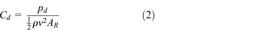
Marine rudder is regarded as a small aspect ratio wing. When uniform flow velocity v is directed toward the rudder section with a certain angle of attack α, 17 the forces acted on the rudder, which is shown in Figure 1.

Forces acting on the rudder.
In Figure 1, b is the chord length,


where
Suppose the rotate speed of the propeller is n and the advance speed is

Movement of the propeller blade element rotating a circle.
Advance coefficient J is expressed in equation (4). The dimensionless coefficient is usually adopted in the study of the hydrodynamic performance of propeller. The thrust coefficient of propeller, torque coefficient, and efficiency formula are expressed in equations (5)–(7)


where T is the thrust, Q is the torque, D is the diameter of the propeller, and J is the advance coefficient.
Governing equations
The governing equations for viscous field are briefly recalled in this section. The different form of the governing equations is written with respect to an infinitely small element. The governing equations for flow field around ship refer to continuity equation and momentum equation.
The physical principle of the continuity equation is that mass is conserved. It can be expressed in terms of equation (8) as

where ρ is the density of water; u, v, and w are the components of velocity along the x, y, and z axes.
The physical principle of momentum equations is Newton’s second law. The resulting equations are called momentum equations. Momentum equations are often called as Navier–Stokes equations. It can be expressed as follows: the net force on the fluid element equals its mass time acceleration of the element. Using Reynolds-averaged method, Navier–Stokes equations can be expressed in terms of equations (9)–(11) as 18


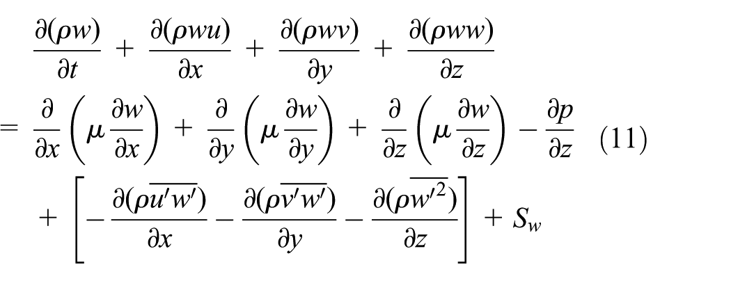
where µ is the dynamic viscosity; p is the pressure on the fluid element; Su, Sv, and Sw are momentum source terms; and
Turbulence model
The renormalization group (RNG)


where k is the turbulent kinetic energy,
The shear stress transport (SST)


where k is the turbulent kinetic energy, ω is turbulence specific dissipation rate,
Blending functions

Two-equation turbulent model is usually used to calculate the turbulent stress by isotropous turbulent viscosity. The influence of rotational flow and the curvature change on the direction of flow is ignored. In order to overcome this shortcoming, it is necessary to establish and solve differential equations of the turbulent fluctuation in the Reynolds equation. Through the dimensional analysis and arrangement, the Reynolds stress equation model can be expressed in equation (16). k and


where
Setup of numerical simulation
Geometry of semi-spade rudder and propeller
The rudder and propeller models adopted in the study are the semi-spade rudder and KP458 propeller, which are designed by the MOERI for the KVLCC2 model tanker. The diameter of the full-scale propeller is 9.86 m, and the number of blades is 4. The geometric models of semi-spade rudder and KP458 propeller are shown in Figures 3 and 4, respectively. The principal particulars of the semi-spade rudder model and the KP458 propeller model are listed in Tables 1 and 2, respectively.

Geometric model of semi-spade rudder.

Geometric model of KP458 propeller.
Principal particulars of the semi-spade rudder model.

Principal particulars of the KP458 propeller model.

KVLCC: KRISO very large crude carrier.
Boundary conditions and grid generation
The geometry and details of the boundary conditions of the semi-spade rudder are shown in Figure 5. The velocity inlet is used for inlet condition. The inlet velocity is set to 10 m/s. The outflow outlet is used for outlet condition. The no-slip wall boundary condition is imposed on the semi-spade rudder surface. When the angle of attack is 0°, structural grids are adopted, and unstructured grids are employed at the rest of the angle of attack. Because there is a gap between semi-spade rudder and rudder horn, modeling and grid discretization are difficult. The grid generation of semi-spade rudder at the angle of attack (0°) is shown in Figure 6.

Computational domain and boundary conditions of semi-spade rudder.

Grid generation of semi-spade rudder at the angle of attack (0°).
The computational domain of KP458 propeller is shown in Figure 7. The surface grids of propeller are shown in Figure 8. The whole computational domain can be divided into two cylinders. The diameter of the outer cylinder is 5D, the length of the outer cylinder is 8D, the distance between the inlet and the center of the propeller is 3D, the distance between the outlet and the center of the propeller is 5D, and D is the diameter of propeller. The inner cylinder in the surrounding of the KP458 propeller is taken as the rotating area. The velocity inlet is used for inlet condition. The outflow outlet is used for outlet condition. The no-slip wall boundary condition is imposed on the KP458 propeller. Multi-reference framework (MRF) technology is employed. MRF technology can deal with more complex motion problems. The watershed can be divided into several static domains and motion domains; interface boundary conditions are used between regions and regions; and the interface of the two regions is set to interface pair. The external region coordinate system is stationary; the inner region coordinate system turns; and the propeller follows the inner region to rotate. In other words, MRF technology can divide the computational domain into different subregions, and the different frame of reference is established in each subregion. In the prediction of propeller hydrodynamic performance, a cylindrical subregion is partitioned into the computational domain to envelop the propeller blades and the hub part of the propeller. In this subregion, the rotation coordinate system is established with the same rotating speed and direction of the propeller. Because there is no relative motion between the propeller and rotation coordinate system, the dynamic rotation of propeller can be converted into static calculation.

Computational domain of KP458 propeller.
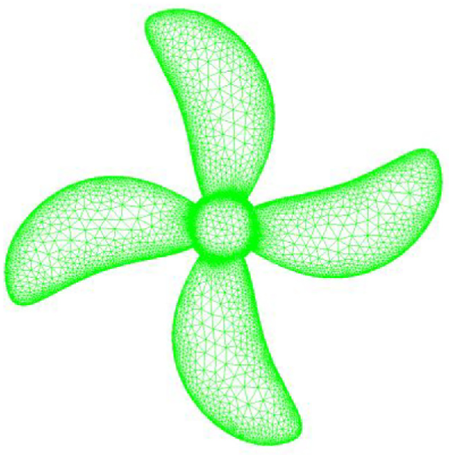
Surface grid generation of KP458 propeller.
The computational domain of propeller–rudder interaction is shown in Figure 9. The whole computational domain can be divided into two cylinders. The outer cylinder is same as the outer cylinder in Figure 7. The inner cylinder around the KP458 propeller is taken as the rotating area. The diameter of the inner cylinder is 100 mm, and the length ranges from −30 to 30 mm. The boundary condition of semi-spade rudder is set as no-slip wall. The other boundary conditions are same as that in Figure 7. The sliding mesh technique is adopted to simulate the propeller–rudder interaction.

Computational domain of propeller–rudder interaction.
Results and discussions
Semi-spade rudder
The calculation results of lift and drag coefficients are compared with the numerical and experimental results. 21 The comparison results are shown in Tables 3 and 4, respectively. The comparisons of numerical and experimental results for lift and drag coefficients are described. Figures 10 and 11 show the curve of lift and drag coefficients at different angles of attack. Numerical results are similar to experimental results, as seen in Figures 10 and 11. When angles of attack of semi-spade rudder are different, pressure distributions on the rudder suction side and rudder pressure side are different. The pressure distributions are described as shown in Figures 12 and 13.
Lift coefficient at different angles of attack.

CFD: computational fluid dynamics.
Drag coefficient at different angles of attack.

CFD: computational fluid dynamics.

Lift coefficient curves of semi-spade rudder at different angles of attack.

Drag coefficient curves of semi-spade rudder at different angles of attack.

Pressure distribution on suction side at different angles of attack.

Pressure distribution on pressure side at different angles of attack.
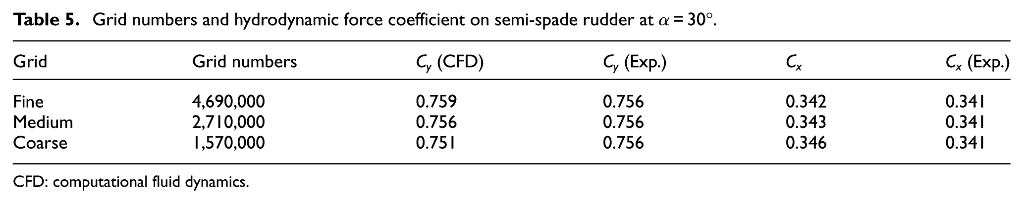
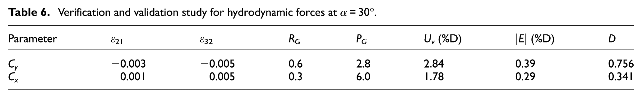
Uncertainty analysis is performed based on the methodology and procedures suggested by ITTC.22,23 Uncertainty analysis for simulation results includes two processes of verification and validation. Verification is defined as a process for assessing numerical uncertainty USN and validation is defined as a process for assessing modeling uncertainty USM using benchmark experimental data. Three different grids (coarse, medium, and fine) are adopted in the verification and validation process. The refinement ratio of fine-to-medium (medium-to-coarse) grids is approximately 1.2. Grid numbers and hydrodynamic force coefficients on semi-spade rudder at angle of attack α = 30° are listed in Table 5. The solutions (0 < RG < 1) exhibit the monotonic convergence condition for three different grids in Table 6. The validation uncertainty for lift coefficient Cy and drag coefficient Cx is 2.84%D and 1.78%D, respectively, where D is experimental data. The absolute value of comparison error E for Cy and Cx is 0.39%D and 0.29%D, respectively, which is smaller than the validation uncertainty Uv. The validation is successful at the present Uv level.
Grid numbers and hydrodynamic force coefficient on semi-spade rudder at α = 30°.
CFD: computational fluid dynamics.
Verification and validation study for hydrodynamic forces at α = 30°.
The flow field of velocity vector is described in Figure 14 for different angles of rudder. The figure indicates that velocity vectors are parallel in the upstream and they can recover parallel along the rudder pressure side and rudder suction side when semi-spade rudder angle of attack is small. With the increasing semi-spade rudder angle of attack, the separation phenomenon of fluid flow around rudder becomes remarkable. When the angle of attack is set to 10°, backflow phenomenon is serious around semi-spade rudder blade. The reason for this phenomenon is that the pressure difference exists between the two sides of the rudder. It generates in such a way that the flow moves from the surface of rudder blade to the back of the blade in the gap between the semi-spade rudder horn and the semi-spade rudder. The velocity discontinuity exists due to the flow around the rudder and the flow near the surface of the backside of the rudder, so the backflow vortex can be generated around the swing section obscured by the rudder horn. The lift performance of this section is greatly reduced under the influence of the backflow vortex. The area of rudder blade is far greater than the area of the rudder blade behind the rudder horn, so the angle of stall is formed when the rudder angle is up to 30°.

Velocity vectors around semi-spade rudder at different angles of attack.
KP458 propeller
The thrust coefficient (Kt), torque coefficient (10Kq), and efficiency (η) can be obtained under different turbulence models and different advance coefficient J, as seen in Tables 7–9, respectively. The comparisons of numerical results and experimental results for the thrust coefficient (Kt), torque coefficient (10Kq), and efficiency (η) are described. For the thrust coefficient (Kt), the numerical results under different turbulence models are smaller than the experimental results, and the numerical results based on RNG k−ε turbulence model are closer to the experimental results. For the torque coefficient (10Kq), the accuracy of numerical results with SST k−ω turbulence model is higher. For the efficiency (η), the results based on RNG k−ε and RSM turbulence model are closer to the experimental results. In numerical simulation, the memory consumption of RNG k−ε and SST k−ω turbulence models is less than that of RSM turbulence model. In the simulation based on SST k−ω turbulence model, it is more difficult to achieve convergence compared to RNG k−ε. For the RSM turbulence model, the eddy viscosity hypothesis is fully abandoned to solve the Reynolds stress differential transport equations. Except that, RSM turbulence model considers the wall’s influence on the distribution of Reynolds stress, so it is more suitable for the numerical simulation of the propeller. However, RSM turbulence model will need more memory and high-quality grids in the simulation. The curve of thrust coefficient, drag coefficient, and efficiency under different turbulence models is shown in Figures 15 –17. The curves show that the thrust coefficient and torque coefficient decrease gradually with the increasing advance coefficient, and the efficiency reaches the maximum value at J = 0.499. Comparison of the propeller open-water characteristics between the experimental and CFD results at different turbulent models is shown in Figure 18.
Thrust coefficient (Kt) data at different advance coefficient J.

CFD: computational fluid dynamics; RNG: renormalization group; SST: shear stress transport; RSM: response surface methodology.
Torque coefficient (10Kq) data at different advance coefficient J.

CFD: computational fluid dynamics; RNG: renormalization group; SST: shear stress transport; RSM: response surface methodology.
Efficiency (η) data at different advance coefficient J.

CFD: computational fluid dynamics; RNG: renormalization group; SST: shear stress transport; RSM: response surface methodology.
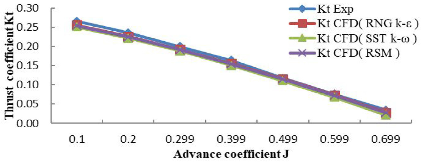
Thrust coefficient (Kt) curves at different advance coefficient J.
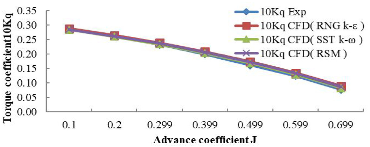
Torque coefficient (10Kq) curves at different advance coefficient J.

Efficiency (η) curves at different advance coefficient J.

Comparison of the propeller open-water characteristics between the experimental and numerical results at different turbulent models.
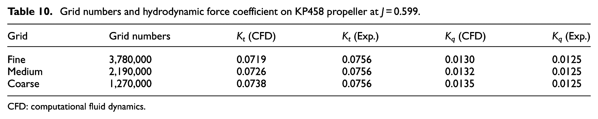
Uncertainty analysis is performed based on the methodology and procedures suggested by ITTC.22,23 Three different grids (coarse, medium, and fine) are adopted in the verification and validation process. The refinement ratio of fine-to-medium (medium-to-coarse) grids is approximately 1.2, which is consistent with Baek et al.’s study. 24 Grid numbers and hydrodynamic force coefficient on KP458 propeller at the advance ratio J = 0.599 are listed in Table 10. The solutions (0 < RG < 1) exhibit the monotonic convergence condition for three different grids in Table 11. The validation uncertainty for Kt and Kq is 5.6%D and 6.2%D, respectively, where D is experimental data. The absolute value of comparison error E for Kt and Kq is 4.9%D and 4.0%D, respectively, which is smaller than the validation uncertainty Uv. The validation is successful at the present Uv level.
Grid numbers and hydrodynamic force coefficient on KP458 propeller at J = 0.599.
CFD: computational fluid dynamics.
Verification and validation study for hydrodynamic forces on KP458 propeller at J = 0.599.

For different advance coefficient, the pressure side and suction side around KP458 propeller are different, as seen in Figures 19 and 20, respectively. With the increasing advance coefficient, the pressure side becomes smaller and smaller. The pressure coefficient of the blade tip of the propeller is the least, which is the most prone to cavitation in this area. The pressure side is higher than that of the blade back, and there is no obvious minimum pressure point, indicating that there is no cavitation in the leaf surface. Figure 21 shows the swirling strength around the KP458 propeller at J = 0.699. The tip vortices generate around each tip due to the pressure difference on the blade and merge with others to form a larger vortex. The hub vortex originates from the center of the hub. The trailing vortices exist around the tip and root of blade. The intensity of tip and hub vortex around KP458 propeller is larger, and a large number of vortexes fall off the blade surface, resulting in severe turbulence.

Pressure distribution on pressure side of KP458 propeller.
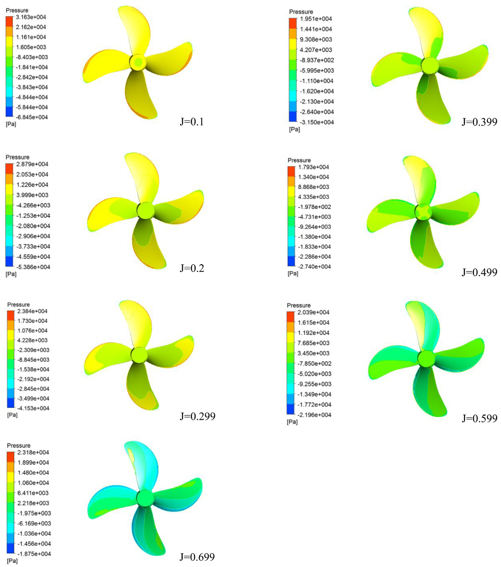
Pressure distribution on suction side of KP458 propeller.

Swirling strength around the KP458 propeller at J = 0.699.
Propeller–rudder interaction
The propeller–rudder interaction is simulated with RSM turbulence model at different advance coefficient and rudder angle α = 0. The average thrust coefficient (Kt) and torque coefficient (10Kq) are calculated. The results of Kt and 10Kq are compared with the experimental results and the numerical results in open water in Figures 22 and 23. The curves show that thrust coefficient (Kt) and torque coefficient (10Kq) increase due to the effect of rudder. Compared to the experimental results in open water, the thrust coefficient (Kt) and torque coefficient (10Kq) increase with the increase in the advance coefficient. The results indicate that when the propeller is under light load, the flow behind the propeller is close to the circumfluence when the advance coefficient is large, and the rudder plays a rectifying role to improve the propeller’s propulsion performance. When the propeller is under heavy load, the flow behind the propeller is close to the jet flow, and the influence of the rudder on the propeller’s performance is inevitably weakened.

Thrust coefficient curves of propeller for open water and propeller–rudder interaction.

Torque coefficient curves of propeller for open water and propeller–rudder interaction.
Different distance between propeller and rudder which is represented as X/D is used in the simulation to analyse the effect on the hydrodynamic performance of propeller, where X is the distance between propeller and rudder and D is the diameter of the propeller. The advance coefficient (J = 0.599) and inlet velocity (V = 2.34 m/s) are constant values in the simulation. The thrust coefficient (Kt) and torque coefficient (10Kq) of propeller under different parameters (X/D = 0.5, 0.75, 1, 1.25, 1.5) are plotted in Figure 24. The figure indicates that the thrust coefficient (Kt) and torque coefficient (10Kq) of the propeller decrease along with the increase in X/D and they trend to the experimental results in the open water. So, the propeller–rudder interaction is weakened along with the increase in the distance between the propeller and the rudder.

Hydrodynamic performance of propeller under different distance (X/D).
The pressure distribution on semi-spade rudder and rudder horn behind the propeller at J = 0.599 is shown in Figure 25. The pressure on both sides of the semi-spade rudder and rudder horn presents an approximate reverse symmetrical distribution, which is mainly due to the effect of the propeller wake on both sides of the rudder surface with an opposite angle of attack. Pressure distribution on propeller for open water and propeller–rudder interaction at J = 0.599 is shown in Figure 26. Compared to the result of the open water, the surface pressure of the propeller increases under the influence of semi-spade rudder. With the increase in rudder angle, the pressure on the propeller surface is further increased. The above results show that the propeller’s thrust performance is improved under the influence of semi-spade rudder. The data shown in Figure 22 also reflect this conclusion. The velocity vectors around propeller and semi-spade rudder at J = 0.599 and α = 0° are shown in Figure 27. It indicates that, due to the effect of semi-spade rudder, the inverse flow at the hub vortex of propeller increases, which makes the pressure on the hub to increase.

Pressure distribution on semi-spade rudder and rudder horn behind propeller at J = 0.599 and α = 0°.
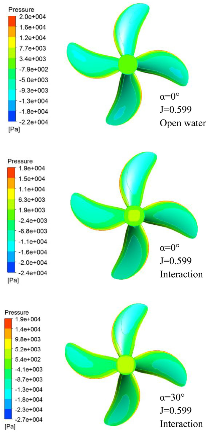
Pressure distribution on propeller for open water and propeller–rudder interaction at J = 0.599 and α = 0°/30°.

Velocity vectors around propeller and semi-spade rudder at J = 0.599 and α = 0°.
Conclusion
The incompressible viscous flow around semi-spade rudder and KP458 propeller is investigated using RANS equations. The hydrodynamic performance of semi-spade with different angles of attack (0°, 10°, 20°, 30°, and 35°) is analyzed by the numerical simulation results. The uncertainty analysis is performed with three different grids (coarse, medium, and fine) for the lift and drag coefficients at the angle of attack α = 30°. The numerical results of the lift and drag coefficients of the semi-spade rudder are satisfied by comparing with the experimental results. The flow field around the semi-spade is analyzed based on the numerical results. According to the simulation result, it indicates that the angle of stall is formed when the rudder angle is up to 30°.
The thrust coefficient, torque coefficient, and efficiency of the propeller are calculated under different turbulence models and different advance coefficients for KP458 propeller. The results show that the thrust coefficient and torque coefficient decrease gradually with the increase in the advance coefficient, and the efficiency reaches the maximum value at J = 0.499. The uncertainty analysis is performed with three different grids (coarse, medium, and fine) for the thrust coefficient (Kt) and torque coefficient (Kq) at advance ratio J = 0.599. The turbulence models RNG k−ε, SST k−ω, and RSM are analyzed for the simulation of KP458 propeller. The pressure distribution and vorticity of the propeller are analyzed based on the numerical results.
The propeller–rudder interaction is simulated with RSM turbulence model at different advance coefficients. The results show that thrust coefficient (Kt) and torque coefficient (10Kq) increase due to the effect of rudder. The hydrodynamic performance of the propeller with rudder is analyzed under different distances between propeller and rudder. The results indicate that the propeller–rudder interaction is weakened along with the increase in the distance between the propeller and the rudder. The pressure distribution and velocity vectors for propeller–rudder interaction are analyzed. The results indicate that the pressure on the propeller increases due to the effect of rudder compared to the result in open water.
Footnotes
Handling Editor: Jianjun Zhang
Declaration of conflicting interests
The author(s) declared no potential conflicts of interest with respect to the research, authorship, and/or publication of this article.
Funding
The author(s) disclosed receipt of the following financial support for the research, authorship, and/or publication of this article: This work was supported by the Natural Science Foundation of Liaoning Province (no. 20170540085), the Doctoral Research Funds of Liaoning Province (no. 201601071), the Fundamental Research Funds for the Central Universities of China (no. 3132018306), and the Educational Reform of Dalian Maritime University (nos 2018Y09 and 2017Y05).