
Abstract
Different loading conditions, different structural dimensions, or different structural materials will lead to different damage results. In this study, blast experiment of steel box model under internal explosion was conducted and the numerical methods are validated through comparison of experimental and numerical results. Then, a series of multi-box models were built, and a large number of numerical simulations considering two kinds of steel, different plate thickness ranging from 0.005 to 0.025 m, and different TNT explosive mass ranging from 5 to 2000 kg were carried out using the validated numerical methods. Two damage modes, convex damage and concave damage, were observed. The dynamic response and damage mechanism were analyzed, and the results show that the different damage modes of the first wall will lead to different damage results of the second wall. Through dimensional analysis, a two-dimensional dimensionless number for internal blast analysis was suggested. Clear physical meanings are conveyed in the dimensionless number. After that, prediction of the damage modes was studied using the proposed dimensionless number. A damage mode map was plotted based on the two-dimensional dimensionless number, and an empirical equation for rapid prediction of damage mode of steel box wall under internal blast loading is proposed.
Introduction
Steel box is the basic component of many structures, such as vans, trains, and ships. Due to the severe situation such as terrorism attack, common undetermined explosion, and collision caused explosion, these structures suffer the threat of internal explosion.1–4
Internal explosions are complicated because the shock wave will reflect several times inside the structure and will be intensified in the structure corners.3,5 As early as 1993, Burman et al. 6 studied the deformation and fracture of a single compartment subjected to internal blast loads, and six events were observed in their study: (1) outward bulging of panels; (2) edges are pulled inwards due to membrane action, and corners remain orthogonal; (3) gross plastic deformation; (4) edge weld rupture; (5) “petalling” and removal of entire panel sections; and (6) gross distortion and collapse of the cubicle. In recent years, some scaled-down experiments testing a model cabin under internal blast load were conducted. Dong et al. 4 studied the interactive mechanisms between internal blast loading and the dynamic elastic response of spherical containment vessels. Ma et al. 7 analyzed the different modes of both ductile and brittle failures of containment vessels when subjected to internal blast loading. Geretto et al. 8 presented a series of experiments of square steel plates under blast loads; they also investigated the effects of confinement and the effect of plate thickness on the ultimate plate deformations.
Numerical simulation, using finite element method programs, has become a common tool in the field of blast impaction because of its advantage of being able to calculate problems with large deflections and high strains.9–11 Wang 12 analyzed the dynamic response of a rectangular steel tube subjected to internal explosion using the finite element software BlastX and LS-DYNA. Nelson and O’Toole 13 surveyed the blast modeling methods available within LS-DYNA and developed a modeling methodology to simulate the blast loading and response of small, hollow composite cylinders, and the model was validated by measured results of instrumented explosive tests. Mehreganian et al. 14 presented a comparative study of numerical, experimental, and empirical techniques on the effect of localized air blast loads on mild steel and armor steel plates. Kakogiannis et al. 15 developed the multi-scale numerical modeling method to predict the dynamic response of Ti-6Al-4 V sheets under blast loading and validated the method with experiments.
Dimensional analysis method is very useful in problems of finding out the main influence factors and building their relationships. Baker and Westine 16 suggested that the similarity method and dimensional analysis should be used in almost every experimental study. In fact, dimensional analysis method has been widely adopted in many dynamic problems.17–20
The present work focuses on analyzing the damage modes of the wall of steel box under internal blast loading. First, blast experiment of steel box model under internal explosion was conducted and the numerical methods are validated. Then, the damage modes and dynamic response were analyzed through large number of numerical simulations. After that, a two-dimensional dimensionless number was suggested through dimensional analysis. Based on the dimensionless number, damage mode map21,22 was depicted and empirical equation was proposed which could be used for rapid prediction of damage mode.
Material models for numerical simulations
Material model for steel
Select a proper material model which is of vital importance in numerical analysis. In this study, *MAT_PLASTIC_KINEMATIC material model 23 is adopted for it is suited to model isotropic and kinematic hardening plasticity, and strain rate effects can be considered in this model. Strain rate is accounted using the Cowper–Symonds model 24 which scales the yield stress with the below factor


where σy is the yield stress; σd is the dynamic yield stress; E and Et are Young’s modulus and tangent modulus, respectively;

where
Material model for TNT explosive
*MAT_HIGH_EXPLOSIVE_BURN is used for explosives, and the Jones–Wilkens–Lee (JWL) equation of state is adopted to model the pressure generated from explosion. It can be expressed as
where the parameters A and B are linear explosion parameters;
Material model for air
Air is defined using the keyword *MAT_NULL, in which air is modeled by linear polynomial EOS and linear in internal energy. The pressure can be expressed as

where E0 is the specific initial energy; V = ρ/ρ0− 1; ci are the coefficients, c4 = c5 =

where ρ/ρ0 is the ratio of current density to reference density, and E0 is the specific initial energy. Under standard atmospheric pressure,
Validation of numerical method
Experimental setup
To validate the effectiveness of numerical method for box-shaped steel structure under internal blast, a steel box specimen was designed and manufactured to conduct internal blast experiment. The box model is made up of 4-mm-thick Q235 mild steel plates with Young’s modulus of 206 GPa. The yield strength and ultimate strength of Q235 steel are 360 and 480 MPa, respectively.
The steel box specimen is shown in Figure 1(b). The side length of all side plates are 600 mm and an extra length of 120 mm is welded to every box side plate for the purpose of simulating the constraint condition. A hole in the center of top plate is manufactured for the purpose of placing the TNT. The final dimension of the specimen is 840 mm × 840 mm × 840 mm. A TNT mass of 98.44 g is selected to conduct the blast test. Four strain gauges are pasted on the outer side of the side wall in order to measure the strain data as shown in Figure 1(a).

(a) Experimental setup and (b) steel box specimen.
Numerical model
The finite element model of the experiment specimen was built by ANSYS 14.5; the model is shown in Figure 2(a). The TNT is defined in the central region of air as shown in Figure 2(b). The eight-node element SOLID164 is used to mesh the explosive and air, while the box model is meshed with four-node element SHELL163. The mesh size of air and box structures is 4 and 5 mm, respectively. The fluid–structure interaction (FSI) algorithm is adopted to model the impacts of blast wave on the box structure. The material models are introduced in section “Material models for numerical simulations.”

Finite element model: (a) box model and (b) air.
Comparison of numerical and experimental results
Figure 3 shows the comparison of damage features obtained from both blast test and numerical simulation. It is obvious that outward bulging of the whole plate is produced in all side plates, and in-plane buckling produces in the central area of all boundary plates. The damage features of both outward bulging and in-plane buckling are observed in numerical results as shown in the right picture of Figure 3.
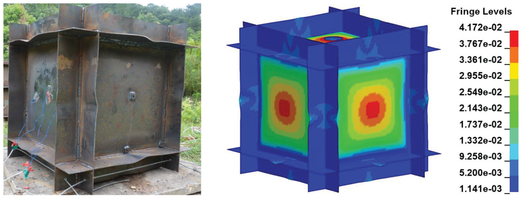
Deformation comparison between experimental result (left) and numerical result (right).
Figure 4 gives the numerical results of the blast load which the side plate experienced. The position of gauging points P1, P2, and P3 was inside of the side plate center, close to the middle of the edge line, and in the corner of the chamber, respectively (as shown in Figure 2(a)). And the shock wave is converged, superimposed, and intensified in the corner of the box for the reason that the corner acted as a focus for convergent shock waves. The convergence of the shock waves caused the pressure and impulse in the corner (P3) to be much higher than that of elsewhere, as shown in Figure 4.

Internal blast loads at typical positions inside the model: (a) pressure–time curve and (b) impulse–time curve.
An ultimate side wall center deflection of 42.82 mm was measured using an electronic digital display depth caliper. The ultimate deflections of simulation results cannot be obtained directly since the calculating time is limited. However, the deflection data after the first extreme value present a phenomenon of oscillation around a specific value as shown in Figure 5. Hence, the ultimate deflection of 41.7 mm could be estimated through analyzing the corresponding deflection–time curves. It shows that the simulation error is about 2.6%. It should be noted that the strain gauges are exfoliated when impact happens, so there is no strain data obtained.
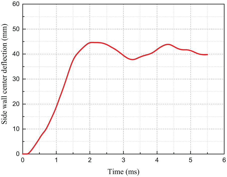
Simulation results of the side wall center deflection–time curve.
The above analysis indicates that the deformation features and deflection data obtained through finite element method are in good agreement with the experimental results, and hence the numerical method is validated.
Damage mode analysis
Simulation cases
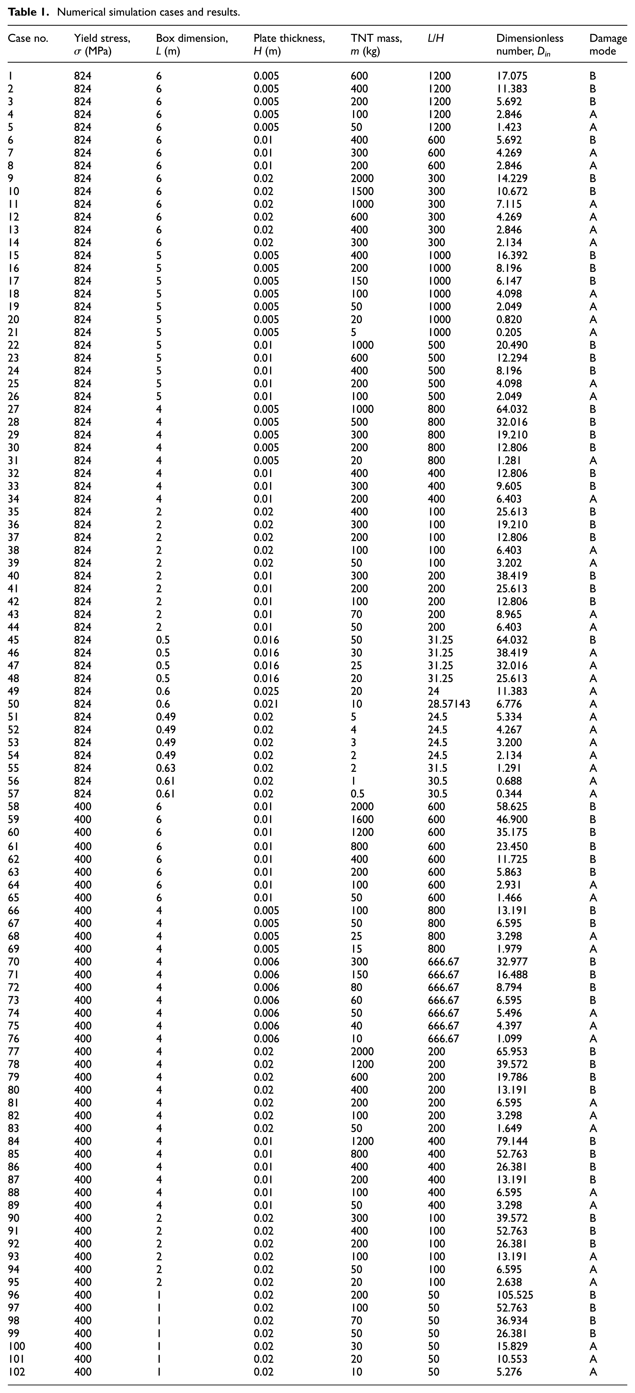
In order to give comprehensive and objective conclusion of damage mode, adequate different damage figures should be obtained, and hence steel boxes with different dimensions under different loading conditions should be considered. In this article, a series of multi-box models are set up and each model includes 27 cubic boxes as shown in Figure 6(a), and the dimension of each box ranges from 0.49 to 6 m as listed in Table 1. In the finite element model, four-node shell element is used to model the steel plate and different plate thickness H is set ranging from 0.005 to 0.025 m, while eight-node solid element is adoped for TNT and different TNT mass m ranging from 5 to 2000 kg was considered. The mesh size of structure and the central region of air are 4 and 1 cm, respectively. These models were set up using the modeling modules of ANSYS 14.0 software and calculations were implemented by LS-DYNA. More than 100 three-dimensional numerical simulations of multiple steel boxes under internal blast loading are conducted (as shown in Table 1, in which

Calculation model: (a) multi-box structure and (b) air.
Numerical simulation cases and results.
Characteristics of different damage modes
Different explosive equivalents or loading conditions, different structural dimensions, or different structural materials lead to different damage results.26,27 While analyzing the results of the numerical simulations, two different damage modes were observed through comparing the damage features of the right side box wall: the convex damage mode and the concave damage mode. The two damage modes were defined as mode A and mode B as shown in Figure 7. The box wall is outward deformed which seems to be “)”-shaped in the central area (convex damage) and the deflection value in the central area is obviously bigger than in the edge area as shown in Figure 6(a). While the wall seems to be inward deformed and “(”-shaped in the central area (concave damage) as seen in Figure 6(b), in fact, it is an outward deformation, the difference is that the deflection value in the edge of the wall is much bigger than that in the central area.
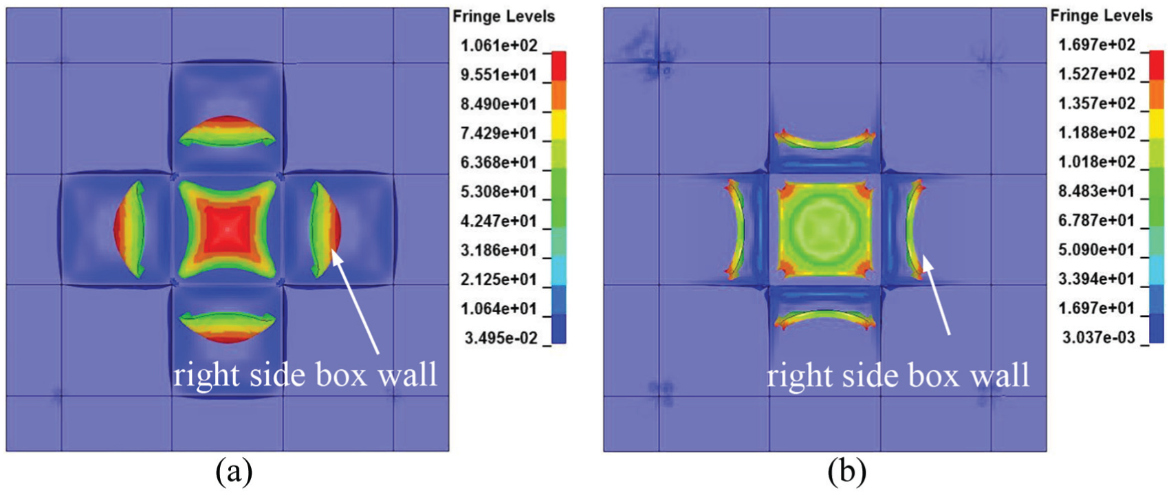
Damage mode of side plate (transverse section view): (a) mode A: convex damage and (b) mode B: concave damage.
Damage mechanism of different damage modes
The dynamic response processes for typical damage mode A are shown in Figure 8. In order to analyze the central box, parts of the model were blanked and section view was presented. Blast wave is produced when the TNT explosive detonated, and the blast wave propagates to the wall of the central box in a very short time. About 2.64 cm deflection is produced at the central area of the wall at t = 0.6 ms (Figure 8(b)). Then, with the increasing deformation, tearing occurs along the edge at t = 1.8 ms (Figure 8(c)). When the wall separates from the central box, “)”-shaped deformation is formed (Figure 8(d)). At t = 14.4 ms, the separated wall reaches the second wall and the central area of the first wall impacts the second wall (Figure 8(e)). When the simulation terminated at t = 22 ms, several cracks produced in the second wall due to the impaction which is showed in Figure 8(f).

Typical dynamic response process of damage mode A (simulation case no. 44, section view, displacement fringe plot, unit: cm): (a) t = 0 ms, (b) t = 0.6 ms, (c) t = 1.8 ms, (d) t = 4.8 ms, (e) t = 14.4 ms, and (f) t = 22 ms.
The dynamic response process of mode B is similar to that of mode A, but there are two major differences. The first difference is when the first wall separated, “(”-shaped deformation is formed (Figure 9(d)), the reason is that the shock wave in the corner and the edge of the box is reflected and intensified which leads to pressure or impulse magnitude in the corner is bigger than that in the central area of the wall. The second difference is that it is the four corners of the first wall that impact the second wall which leads to cracks that are first produced in the edge of the second wall. Finally, the second wall is damaged and separated from the specimen almost as a whole plate.

Typical dynamic response process of damage mode B (simulation case no. 79, section view, displacement fringe plot, unit: cm): (a) t = 0 ms, (b) t = 1.2 ms, (c) t = 1.8 ms, (d) t = 9.0 ms, (e) t = 19.2 ms, and (f) t = 22 ms.
Discussions
Dimensionless numbers for internal blast analysis
By analyzing the results of simulations and experiments, we found that the damage modes of box wall under internal blast loads are influenced by many factors, such as the amount of explosive, and the strength and dimension of the structure. Dimensional method is introduced here, and the relationship is expressed as follows

where dm is defined as the damage mode, and V and
To simplify the analysis, the sound velocity and the density of steel and air can be neglected for they could be deemed as constants in this problem. A dimensional analysis is processed using the Π law, then

where

Equation (7) can be written as

Then, the damage mode is determined by three dimensionless terms.
28
A dimensionless number for internal blast includes the influence of the blast loads, the resistance ability of the material, and the dimension of the structure defined as

where Q = EeV is the total explosive heat. It can be noted that the damage number
However, for some complicate problems which need two-dimensional analysis, and the plate’s dimension–thickness ratio (L/H) is a main variable which considers the influence of structure dimension, the two-dimensional dimensionless number is defined here as

Damage mode map
Display the damage mode data from Table 1 in the coordinate system of the two-dimensional dimensionless number
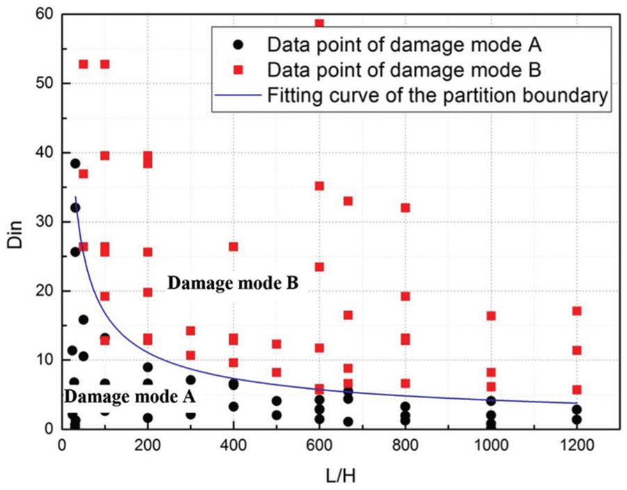
Damage mode map under two-dimensional dimensionless number coordinate system.
The two damage modes have distinct boundaries from each other, so they can be partitioned using demarcation line which is shown in Figure 10. The fitting curve of the partition boundary can be expressed as
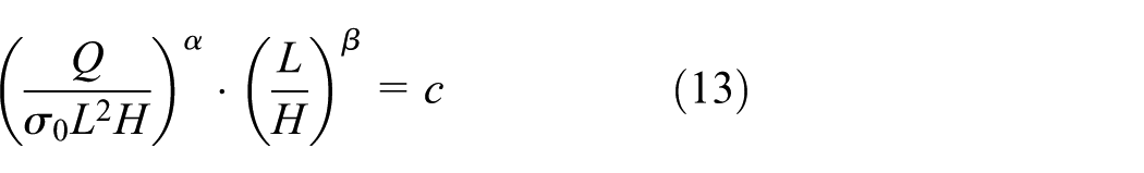
where α = 1, β = 0.598, and c = 262.965.
For any internal blast cases within the range of this study, the damage mode can be quickly predicted using the damage mode map as long as the parameters of the material, structural dimension, and explosive volume are given.
Concluding remarks
This article addresses the study on the dynamic response of steel box wall and explores useful and convenient method to predict the damage modes of multiple steel boxes subjected to internal blast loading on various loading conditions.
Blast experiment of steel box model under internal explosion was conducted and the numerical methods are validated through comparison of experimental and numerical results. Then, a series of multi-box models with the dimension of each box ranging from 0.49 to 6 m were built, and a large number of numerical simulations considering two kinds of steel, different plate thickness ranging from 0.005 to 0.025 m, and different TNT mass ranging from 5 to 2000 kg were carried out using the finite element software ANSYS/LS-DYNA.
Through analysis of numerical results, two damage modes of the box wall were observed, namely, convex damage and concave damage. The damage mechanism and dynamic response process of the two damage modes were analyzed, and the results show that the different damage modes of the first wall will lead to different damage results of the second wall.
Through dimensional analysis, a two-dimensional dimensionless number for internal blast analysis was suggested. Clear physical meanings are conveyed in the dimensionless number. After that, prediction of the damage modes was studied using the dimensionless number proposed in the study. A damage mode map with the two-dimensional dimensionless number coordinate system is plotted. An empirical equation for rapid prediction of damage mode of steel box wall under internal blast loading is proposed based on the damage mode map.
Footnotes
Handling Editor: Jianjun Zhang
Declaration of conflicting interests
The author(s) declared no potential conflicts of interest with respect to the research, authorship, and/or publication of this article.
Funding
The author(s) disclosed receipt of the following financial support for the research, authorship, and/or publication of this article: The research reported in this article was supported by the National Natural Science Foundation of China (no. 11202236).