
Abstract
This study focuses on quadcopter flight control and image application. The proposed quadcopter can be applied to inspect rust or damage areas of ship hull. Real-time image identification with proper devices is also proposed. Proportional–integral–derivative control and fuzzy control are used in flight control design. Due to hardware limitation of the quadcopter, complicate control theory is avoid in controller design. A simple fuzzy control is used in this study. In sensor fusion, air pressure altimeter, Global Positioning System (GPS), ultrasonic sensor, and optical flow sensor are utilized to maintain altitude holding in outdoor and indoor environments. In color identification, Pixy (CMUcam5) camera is used to perform image processing and image tracking. Signals from different sensors are processed in the Arduino board. In flight simulation, pitch and roll angle commands are constructed in a rule table. Flight control can be performed by feedback tracking error, and software simulations for proportional–integral–derivative and fuzzy control are given.
Keywords
Introduction
In past decade, the unmanned aerial vehicles (UAVs) have been widely used in aerial photography, surveillance, advertising, and filming. Recently, the most used UAV is the multirotor vehicle, especially the quadcopter. For proper operation, further understanding of dynamic quadcopter program and control designs in the experiment are essential. Our goal is to design a quadcopter that can inspect object surface. Conventional structure inspection or crack detecting inspections are based on human visual inspection. Most of time there are always inaccessible areas and limitation for detection. The UAV will be helpful for this kind of tasks.1–7 In this study, a ship model is set up as the object. This model is used to conduct real tracking flight and object detection. The real flight was integrated by multiple sensors. With the values of all aspects of sensors in Arduino mega 2560 and signal integration in program, the quadcopter can fly around the target in reality and catch the predefined target color as hovering point automatically.
In this study, references8–10 are applied to conduct the design of proportional–derivative (PD) controller and state feedback control law for the proposed quadcopter system. Moreover, we utilize references11,12 to simulate and adjust PD gains, flight direction, and object tracking. Fuzzy PD control system is also applied to control flight attitude.13,14 After software simulations, we will then test hardware APM2.6 flight control board and integrate remote control (RC) radio, 3DR number biography, Pixy CMUcam5, and ultrasonic measurement components. The pitch and the roll angle of the rule table can be adjusted by setting to manual or automatic mode through RC radio.15,16 Pixy (CMUcam5) camera is used to implement image tracking that can acquire objects’ color and then feedback to the Arduino processor, and track objects area corresponding to the spatial position and the distance from the quadcopter.
This research focuses on quadcopter dynamic model, simulation, and sensor components that are used in a rotary-wing aircraft. We apply sensor components to make the quadcopter utilize air pressure altimeter with the ultrasonic sensor components to accomplish altitude holding in hostile environment. Ultrasonic sensor components are used in autonomous obstacle avoidance. Compared to conventional PD control, the results of fuzzy PD control truly improve the efficacy of the flight performance. The proposed quadcopter system will be applied to inspect ship hull. Ships need to be inspected when dock, sometimes the workers climb or hang out of the ship and check whether there is any rust or destruction. Having the quadcopter with automatic flight and image tracking capability, surface of a ship can be auto detected and inspected efficiently. In the future, crew members will not be required to check the exterior condition of a ship in hazardous environment.
System description
A quadcopter is a multi-axis aircraft and is lifted by four rotors. It is different from a fixed-wing aircraft, the quadcopter takes off with the rotation of the propellers. The rotors of the quadcopter have same size and are setup at symmetrical position. By adjusting the relative speed between different rotors, we can adjust torque and control stable flight, rotation, and turning of the quadcopter. This is different from a helicopter which has only two rotors. In a helicopter, the major rotor provides lifting force, and the minor rotor is responsible for the function of counteracting the torque produced by the main rotor, and controlling rotation of the helicopter. In the UAV market, most quadcopter’s main structure has cross steel body with four direct current (DC) motors.
10
The four rotors provide power source with required thrust and change of flight attitude. Quadcopter’s flight condition is controlled by the voltage’s adjustments which are inputs of the four rotors.
17
The steering of two of the four rotors are forward, and the other two are opposite, as shown in Figure 1,
18
where
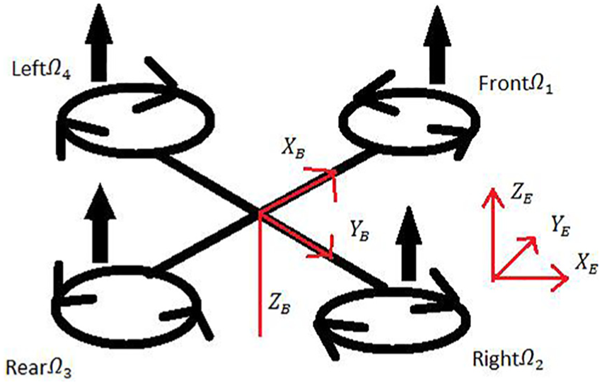
Coordinate system of a quadcopter.
The attitude and displacement of a quadcopter are controlled by different speeds of its rotors. The attitude is divided into three parts, which are roll, pitch, and yaw. Before derivate the equation, it is essential to set some basic hypothesizes:
The structure of quadcopter is symmetrical rigid body.
The propellers are rigid bodies.
Thrust and torque equal propeller’s speed squared.
The barycenter coincides with the origin of coordinate.
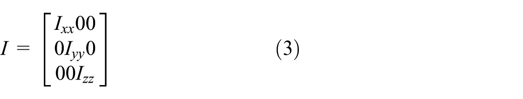
The definition of coordinate is indicated in equations (1) and (2)10,11,17


There are torques of each coordinate’s axis for the quadcopter’s basic hypothesizes, and attitude equation can be obtained as
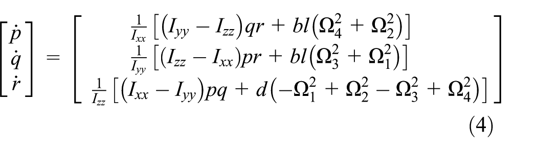
where b is thrust parameter, l is shaft length,

where
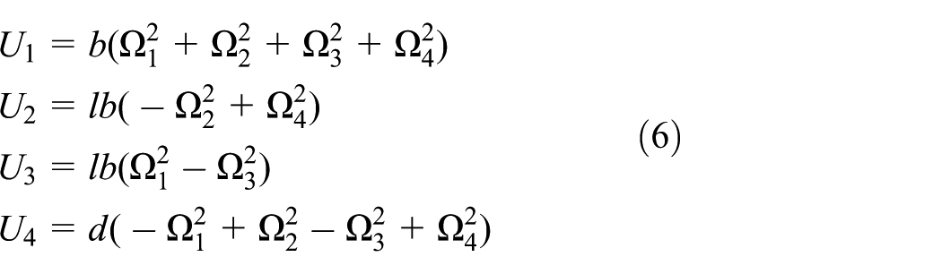
Equation (4) is attitude motion and equation (5) is displacement motion. The following is to simplify the equation of motion of the quadcopter through equation (6). From equation (6), we know that
The hypotheses aiming at hover point linearization are

In this case, the subscript h means the value when hovering, and the mark

From equation (8), the attitude of the quadcopter only relates to U, and displacement control is related to U and attitude angle. The result is in accordance with the physical characteristics of the quadcopter. Therefore, the attitude control belongs to inner controller, and the displacement control is outer controller. Put in other words, it needs corresponding attitude inclination to control the displacement. The control procedure is shown in Figure 2.

The diagram of control procedure.
The following will probe the attitude of the quadcopter, which is the inner controller in Figure 2. The next step is to probe the procedure of the attitude control in advance. Figure 3 shows the diagram of the attitude control procedure, and
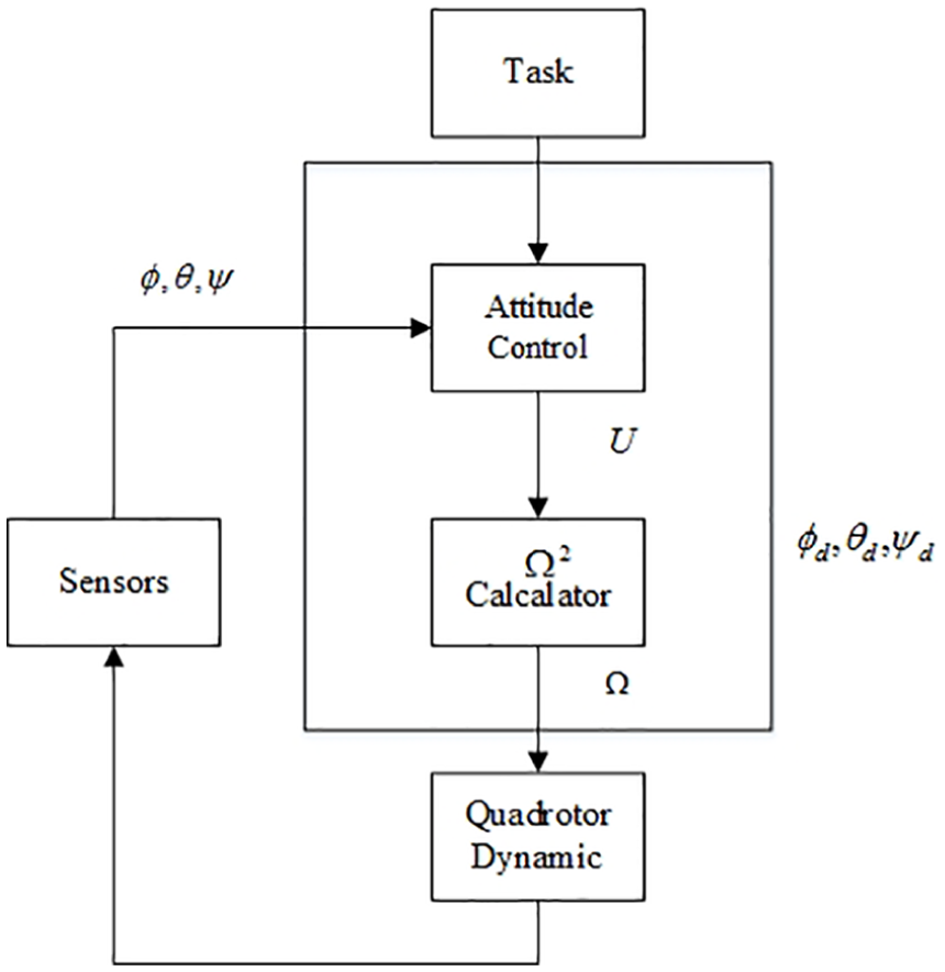
The diagram of the attitude control procedure.
The block of attitude control is PD attitude controller designed in next section. The block of rotation speed squared calculator (

Then, substitute the rotation speed into the block of the dynamic equation, attitude changes of the quadcopter can be found. Feedback the value of attitude to the attitude control block, this completes the closed-loop control. Before designing the controller, the transfer function is needed. The Laplace transform functions can be obtained as follows


Control scheme
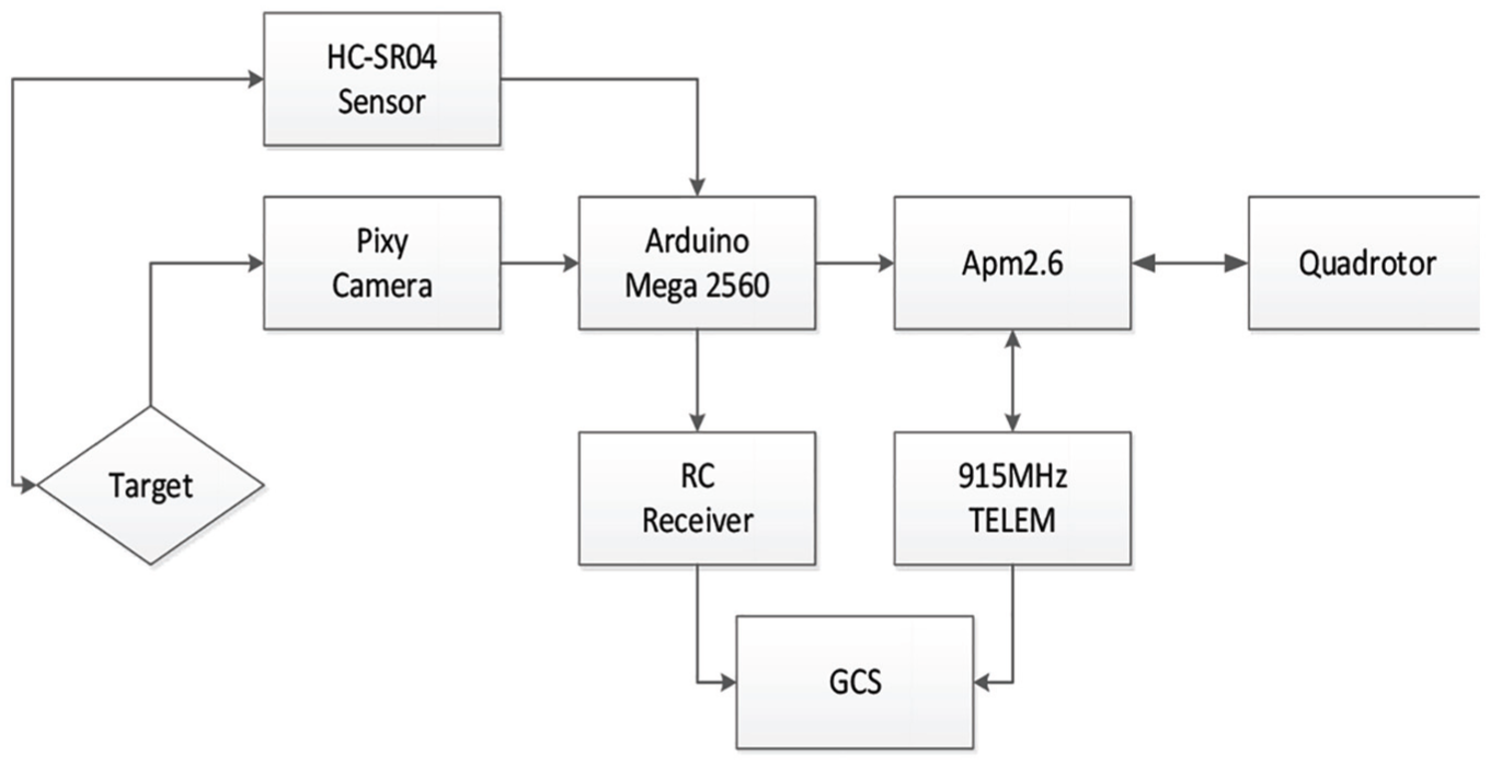
Flowchart of the control sequence is shown in Figure 4. First of all, due to manual control when taking off, the remote controller must be switched to optical flow mode or Global Positioning System (GPS) mode when flying to certain height. Under the mode of optical flow or GPS, loiter mode would be fixed. The way of loiter mode in indoor control is to use light sensing element for hover, and ultrasonic sensor element for altitude hold. The outdoor GPS provides coordinates for hover, and barometric pressure as well as ultrasonic for altitude hold. If target is a boat, the quadcopter would start tracking the target under normal GPS mode. Moreover, target tracking also switches to auto tracking on the remote controller. The quadcopter tracks a target using pixy cmucam5 to catch the signal of tracking source and then sends to Arduino Mega 2560 through Serial Peripheral Interface (SPI) to check whether it is the right target or not. Using pulse-width modulation (PWM) signals are sent to APM 2.6 flight control board to control the direction of the quadcopter, then adjusts direction and flies around the target slowly at the same time. APM 2.6 can control the quadcopter to fly toward the target precisely with the use of pixy camera. The ultrasonic sensor provides the information for obstacle avoidance and keeps a safe distance when the quadcopter and the target are too close. Figure 5 shows the RC receiver and Arduino Mega controller that are used. 18
Flowchart of control sequence.

(a) RC receiver and (b) Arduino Mega controller.
Direction control and obstacle avoidance
When Arduino Mega controls the output values of direction, there exit great pulses if the remote controller dose not move. Some of the number of pulses would be more than 50; thus, averaging process is given that every 10 output values from the Arduino Mega are averaged. Because of the noise pulses, control signals from the Arduino Mega are affected greatly. We set up an averaging process as a filter to reduce the effect from the noise. We have tried different numbers in averaging process, 10 is best number for averaging usage. This can effectively reduce noise pulses. After averaging process, there might have small number of pulses, but the value would be less than 10. For the quadcopter, this kind of small pulses will not make the attitude of the quadcopter change instantly and the change is also small. Figures 6 and 7 are remote controller analyzing data which without averaging process and with averaging process, respectively.
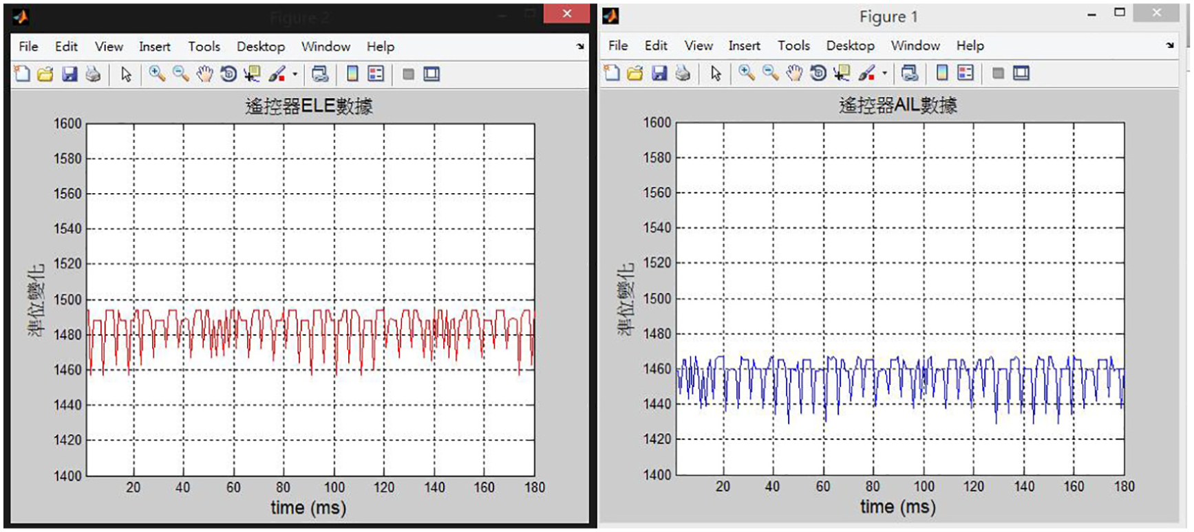
None averaged remote controller values.

Averaged remote controller values.
When it comes to obstacle avoidance, ultrasonic sensors are installed at the bottom of each four faces of quadcopter to accomplish obstacle avoidance and altitude hold, as shown in Figure 8. Detection distance of the ultrasonic sensor is approximately 2 cm to 3 m, burst frequency is 40 kHz, current is 30 mA, and the voltage is 5 V. These four ultrasonic sensors trig, echo, and link to the pin of Arduino Mega. The four faces of the quadcopter can detect object if there are obstacles beside the ultrasonic sensors. If the ultrasonic sensors detect obstacles, then performs go around displacement for the quadcopter. Figure 9 is the flowchart of obstacle avoidance control.

Quadcopter with ultrasonic sensors.

Flowchart of obstacle avoidance control.
Optical flow hover control
At hover point, the quadcopter appears drift phenomenon resulted by inertia. At this time, the optical flow sensor can be used for hover control. Optical flow sensor (Optical Flow v10) is used to obtain x-axis and y-axis coordinates so that the quadcopter can be kept at the hover point. The optical flow sensor aims at improving accuracy in the environment that cannot use GPS. Software Python 2.7 is used to ensure if there are sensing values. In the interface of Python, Python IDLE editor is started up and entered “c” to ensure whether the sensor responses to APM 2.6 board. After ensuring, entering “m” inspects whether x and y values change or not, as shown in Figure 10. Figure 11 shows the interface command of Python IDLE and the image of sensor. Turn on the Mission Planner at the ground control station to set up optical flow mode, and switch the remote controller to optical flow mode, then the quadcopter can hover, as shown in Figure 12.

x and y values read by the sensor.

The interface command of Python IDLE and the image of sensor.
Optical flow sensor to hover point.
Image tracking
In image tracking control, the Pixy camera is used. In this study, we only inspect rust or damage area of ship hull, which most likely are black and brown colors. These colors are preset to the Pixy camera. Since hull colors of most ships are simple, the Pixy camera is a very good color detector for this study. Preset colors can be detected in very short time and is suitable for real-time control usage. The Pixy camera is connected to Arduino Mega board, as shown in Figure 13. It sends block information to Arduino at 1 Mbits/s which means Pixy can send more than 6000 detected objects per second or 135 detected objects per frame (Pixy can process 50 frames/s). Captured image data are sent to Arduino Mega through SPI interface. PWM signal is sent to APM 2.6 board to control the quadcopter to fly around the object, as shown in Figure 14. Pixy uses color filtering (hue-based color filtering algorithm) to identify objects. It can also detect various colors and can read seven different colors’ directions and area at the same time, as illustrated in Figure 15. Figure 16 shows image values of the seven colors, which are set in Pixy software. Image processing is based on the two-pass algorithm 19 ; the parameter values of the colors can be adjusted for Arduino Mega to control the quadcopter. If the first of the two colors set in the image is green, and the second one would be red. When the second color appears in the first color, the captured image will be sent to the control center as the final target, as shown in Figure 17. In Figure 17, we assume the color of the tested ship hull is green and the rust area is red color. Since the color of a tested ship is known, different colors can be preset to the Pixy image processing prior to each inspection.

Pixy camera with Arduino Mega.

Direction control on captured obstacle.

The interface of reading the size and direction.

Interface of parameter values of different colors.

The two desired colors, green and red, captured from the camera.
PD control
The following is to conduct the PD control toward the attitude transfer function of quadcopter. The block diagram is illustrated in Figure 18, where

The block diagram of attitude control.
A simplified model can be obtained as follows. System settling time, natural frequency, and damping ratio are chosen from Li, 11 as shown below

Substitute the values of natural frequency and damping ratio into standard second-order system and gets

After calculating

After getting the transfer function of attitude control, the PD controller can be designed. First of all, the suitable inner loop parameter value should be discovered. By the use of Root Counters we can find out the most steady gain value. In Figure 17, the root locus that the left half plane is stable would be depicted, and seek for the parameter values sequentially in the red box. The upper left corner of Figure 19 is Kp. Entering the Kp value gets the upper right corner picture which is Kd. The lower corner figure, Ki, is gotten after keying Kp and Kd values. In the part of Ki is discovered that appearing unstable state. Thus, the needed gain values are set up as two values of PD for ensuring the stable condition of the system. The outer loop parameter values are chosen by the same way.
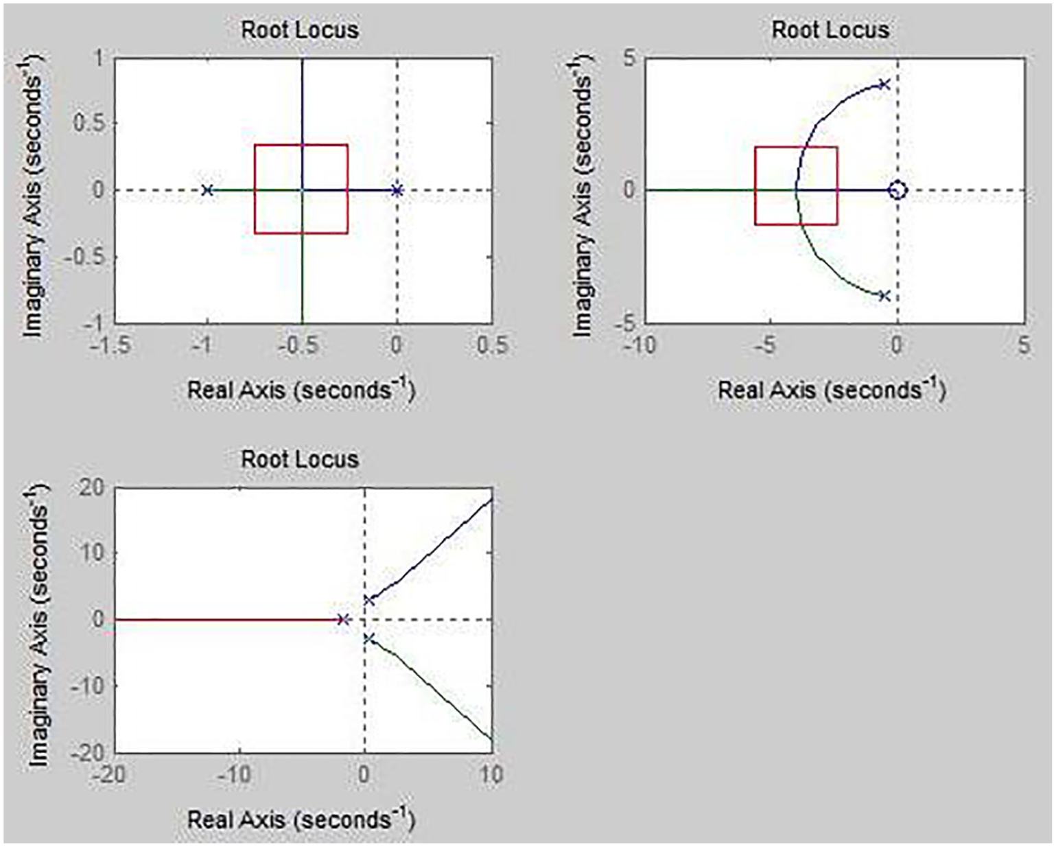
The gain values of the root locus.
Fuzzy PD control
The PD control is implemented in fuzzy system. 12 Fuzzy control design does not need to analyze complicated mathematical model. Fuzzy controller design can be completed by experts’ rule of thumb. When applying various quadcopters’ condition, the fuzzy theory can be used with less parameters adjustment. Due to its high applicability and practicality, the fuzzy design technique has been utilized in this study. Input error e and error change rate de then proper parameter Kp and Kd can be obtained that satisfies demands from different e and de toward the controller parameter values and makes the dynamic and static responses better. Control block diagram is shown in Figure 20.

Fuzzy PD control.
The construction of fuzzy control in this study uses built-in fuzzy tool in MATLAB. Concerning to the degree of coverage of discourse, sensitivity, and stability, this study applies different triangular membership functions used by fuzzy subset, as shown in Figures 21 and 22. According to the relationship between error and error change rate, the rule base of each PD parameter values is constructed and corresponds to the output of the membership function, as Figure 23 and Table 1. In line with fuzzy rules, for various combinations of all input linguistic variables, each state of output fuzzy control is calculated by fuzzy logic inference and defuzzification method. Also, the input and output membership functions and the exact values of the

The membership functions of error e.
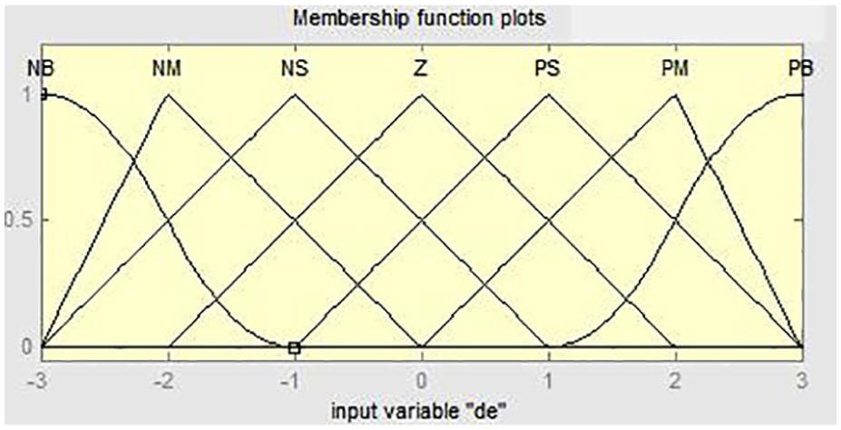
The membership functions of error change rate de.

Output membership functions.
Fuzzy rules of output.

Experiment results
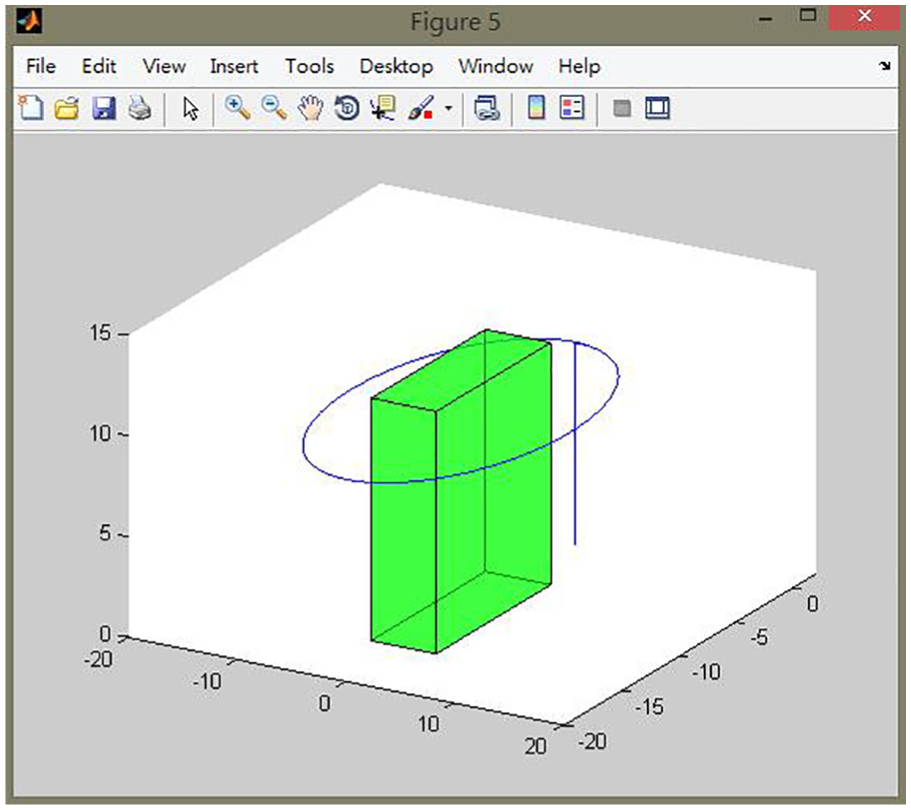
In quadcopter’s simulation, the dynamic equation and transfer function of each system are constructed to Simulink by the MATLAB package software. In the simulator, the values of parameters and controller gains are from references9,10 and Lee et al. 18 There are two major system blocks, which are the quadrotor and the guidance law systems. The former is responsible for simulating the dynamic response of quadcopter. The latter gives the dynamic system commands such as x_cmd, y_cmd, z_cmd, and yaw_cmd, with the location of the feedback after calculation. The design task is to move height, X-direction, and Y-direction sequentially. The height is set to 10 m, X-axis displacement is 10 m, and Y-axis displacement is 10 m. It was set to fly along a circle and the simulation is shown in Figure 24.

Simulated mission trajectory.
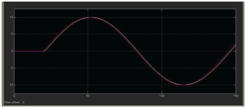
Figures 25–27 are the actual flight profile of the aircraft in X-, Y-, Z-axis by PD control.10,18 Figures 28 –30 are the actual flight profile of the aircraft in X-, Y-, Z-axis by fuzzy PD control. Purple line stands for reference and yellow line represents the actual flight curve. There is a time delay that waits for the aircraft rising up in the Z-axis motion and then circling the object. In X-axis and Y-axis motions, the performance of PD control and fuzzy control is very similar. In Z-axis motion, fuzzy control has no overshot but takes more rising time.
X-axis direction command and response by PD control.

Y-axis direction command and response by PD control.

Z-axis direction command and response by PD control.

X-axis direction command and response by fuzzy PD control.

Y-axis direction command and response by fuzzy PD control.

Z-axis direction command and response by fuzzy PD control.
In the experiment, optical flow mode is applied when the quadcopter flying indoor, and GPS mode is applied when flying outdoor, as shown in Figure 31. 10

Indoor optical flow mode and outdoor GPS mode: (a) indoor and (b) outdoor.
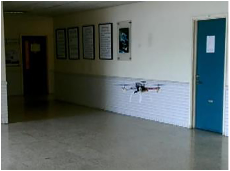
In actual test of target tracking and obstacle avoidance, a target is tracked autonomously. Simulation result is shown in Figure 32. The quadcopter can perform circling flight and obstacle avoidance capabilities, as shown in Figures 33 and 34.
Simulation of circling an object.

The test of circling around a target.

The test of obstacle avoidance.
In outdoor test, an object is set in front of the quadcopter, and let the quadcopter maintain tracking and detecting when flying around. While detecting specified color, the quadcopter will stay hovering in front of the desired color. The results of experiment are shown in Figure 35. Figure 36 shows that the specified target is detected. Specified target can be located as shown in Figure 37.
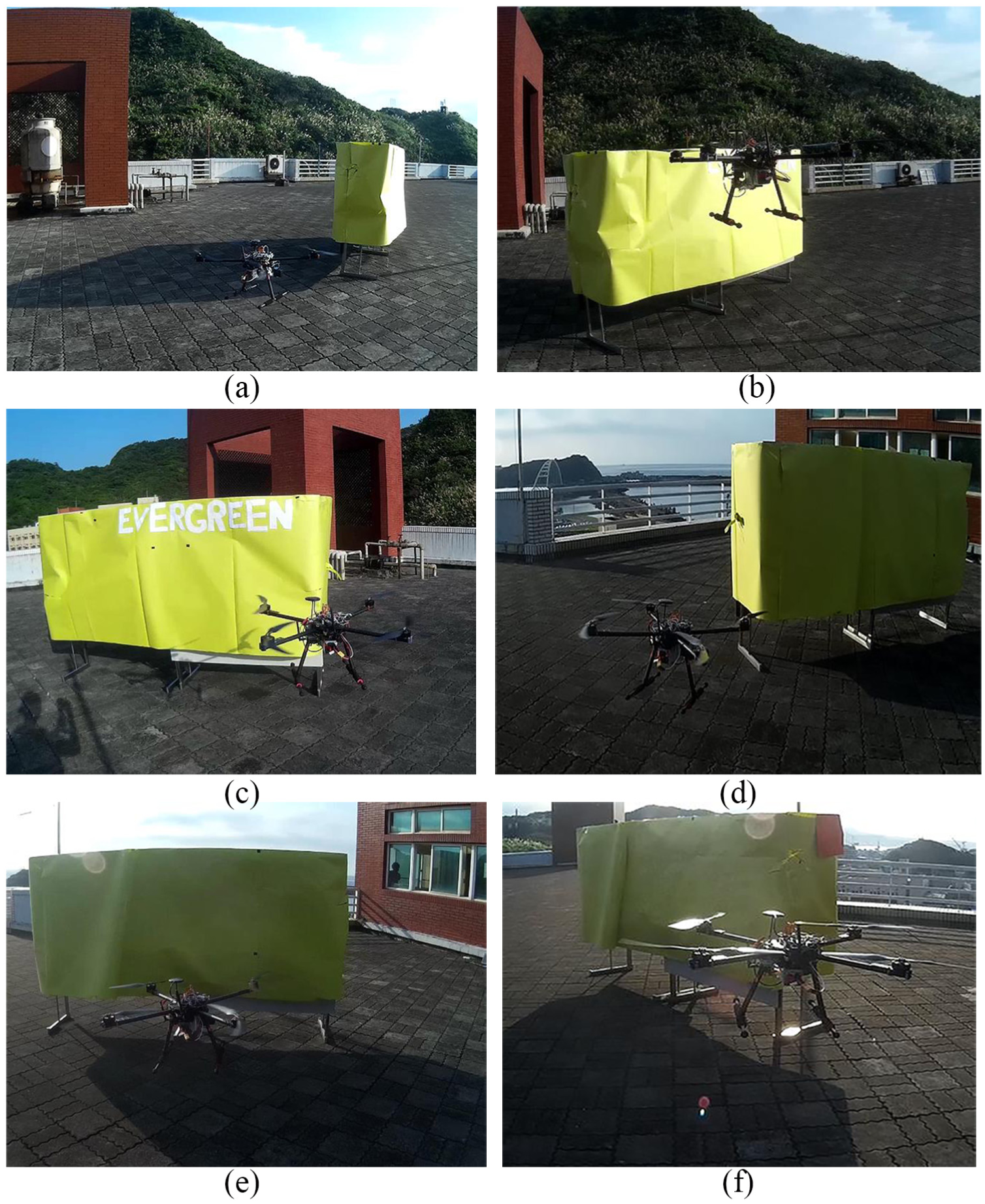
Outdoor experiment using GPS: (a) starting point, (b) circling the object, (c) circling 1/4 object, (d) circling 1/2 object, (e) circling 3/4 object and (d) circling 7/8 object.

The final target was detected: (a) hover at the specified target and (b) the specified target.

Latitude, longitude, altitude of the specified target from the GPS.
Conclusion
The main point of this study focuses on quadcopter flight simulation and sensors integration. The originality is that the proposed quadcopter can be applied to inspect ship hull. Real-time image identification with proper devices is also proposed. Proportional–integral–derivative (PID) control and fuzzy control are used in flight control design. Due to hardware limitation, we do not want to use complicate control theory. Flight control rule must be as simple as possible. Hence, a simple fuzzy control is applied in this study and the fuzzy control is not the main point of this study. In flight simulations, output response of the conventional PD control can be improved by the fuzzy PD control. The overshoot in transient response of the PD control was reduced by the use of fuzzy control. In addition, using less fuzzy sets for control parameters will have less settling time in transient response, but the drawback is that the overshoot in transient response will increase. Because Taiwan harbors are forbidden and inaccessible areas, real ship is unreachable. So we set up a model to emulate a ship object. Real tracking flight and object detection was performed around this model. The quadcopter flied around the emulated model and searched the predefined color of rust or damage area. Target colors were preset for image processing by the Pixy camera, and seven colors can be used for the Pixy camera. Flight direction of the quadcopter was controlled by the predefined color and the size of the desired target image. Once the target color was caught, the quadcopter will hover at that position. Location information of the target can be sent back to the control center via wireless communication. Programs of different experiments are supposed to be written into the APM 2.6 flight control board, but it is hard to expand on the aspect of function. Due to 8-bit processor memory and CPU performance in APM 2.6 flight control board, the memory is saturated and different experiment codes cannot be embedded into it. A new product Pixhawk flight control board, 32-bit memory and CPU performance, can be utilized in the future. Another problem in our experiments is the wind disturbance. Proper wind model in control system design will be our future work.
Footnotes
Handling Editor: Daxu Zhang
Declaration of conflicting interests
The author(s) declared no potential conflicts of interest with respect to the research, authorship, and/or publication of this article.
Funding
The author(s) received no financial support for the research, authorship, and/or publication of this article.