
Abstract
The influences of groove bottom texture, in the form of orientation structure with various width, depth, spacing, and different operation parameters, on orientation effect have been investigated by numerical analysis. The results show that the existence of texture and the change of direction have strong impacts on the orientation effect, and opening force and leakage increase due to the effect. The increment in the opening force and leakage is more remarkable when film thickness is small and the shaft speed or medium pressure is high. The orientation texture makes the performance of dry gas seal more stable, which is more significant for extreme working conditions. An optimal texture model was built and an efficient and cost-saving method of laser surface processing for the orientation texture was put forward.
Introduction
Dry gas seal (DGS) with laser surface texturing (LST) is widely used in high-speed rotating equipment due to many advantages, including low friction and wear, low leakage rate, and long running life.1–3 The quality of the surface is often of the most importance for the properties of DGS and it is well-known that surface roughness plays an important role in deciding the hydrodynamic behavior during the operation. Patir and Cheng 4 first established an average flow model (PC model), which represents the effect of roughness by introducing flow factors. Makino et al. 5 extended the PC model and applied it to the thin film gas lubrication on the basis of several previous researches,6–8 and this model has become an ideal method to study the lubrication effect of surface roughness. Peng and colleagues9,10 analyzed the sealing properties of DGS with surface roughness in different areas based on PC model, which indicates that the opening force, stiffness, and friction torque of the smooth end face are better than that of the coarse end face under the same working conditions and meanwhile the leakage is smaller. These researches show that ignoring the influence of roughness will result in a large deviation from the actual ones. Thomas et al. 11 presented a numerical modeling of thermo-elasto-hydrodynamic mechanical face seal behavior, concluding that the surface distortion has a great influence on the gap geometry and mechanical seal performance. It indicates that any distortion of micro-scale clearance will significantly affect the hydrodynamic characteristics. Shahin et al. 12 optimized the groove bottom of spiral groove dry gas seal (S-DGS) and found that the tapered-type spiral groove can reduce seal opening force and leakage rate. Su et al.13,14 considered the roughness interaction when studying the thermo-hydrodynamic behavior of bidirectional DGSs and the results indicate that there exists a critical minimum gap affected by roughness. These researches demonstrate that the structure and roughness of DGS groove bottom can be optimized and the optimal value exists.
In summary, the micro-scale change of the groove shape or the bottom of the DGS has a great impact on the seal performance parameters, so it is of great significance to explore the improvement in the surface texture to improve the DGS performance. Studies in recent years15–17 have shown that reasonable texture design can better improve the behavior of random roughness on the dynamic performance of micro-scale clearance. Texture reconstruction or design of rough surface can improve friction performance and sealing stability.
In conclusion, groove bottom texture and its reconstruction could significantly affect the performance of DGS. In this article, a type of T-groove dry gas seal with orientation texture (TT-DGS) dealt with LST is introduced to improve performance and simplify slotting process. A physical model is developed to study the orientation effect of the texture at the groove bottom. The influences of orientation effect on opening force and leakage have been numerically analyzed. This method is expected for providing a guide for practical engineering application.
Theoretical analysis
Theoretical basis
Figure 1 shows the different flow forms under different damping modes during the flow process. When the fluid is damped by obstruction, the flux and velocity gradually reduce (Figure 1(a)). When the flow is in an orientation mode as shown in Figure 1(b), it will successfully pass the channels without decreasing flux and velocity. Therefore, when the sealing face is in the orientation mode, the orientation effect can stimulate the flow and improve the orderliness of fluid flow. Accordingly, the extrusion effect and opening force of the medium can be increased.
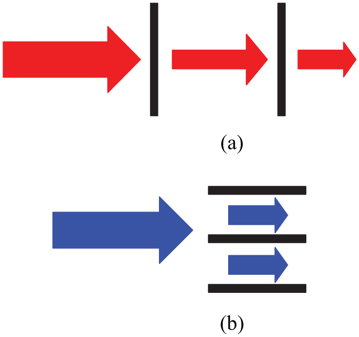
Schematic diagram of flow state with different damping modes: (a) damping effect and (b) orientation effect.
Design analysis
At present, roughness of the non-grooved region and the static ring end face of DGS ring are about 0.1 μm in current processing level and 0.8 μm for the bottom region. Assuming that non-grooved region and static ring end face are smooth, while the bottom of the groove is rough and the roughness is isotropic, as shown in Figure 2(a). Based on scanning path, LST technology can achieve certain texture profile. Assuming that the scanning path is consistent with fluid flow, the sculpted shape will be in order. As can be seen in Figure 2(b), the orientation effect of the orderly pattern is better than the random pattern.

Three-dimensional schematic diagram: (a) random pattern and (b) orderly pattern.
A relevant research 18 shows that, the three-dimensional (3D) rough surface based on Gaussian distribution function and exponential auto-correlation function is conformed to the mathematical model of the seal face, and it can represent the isotropic random surfaces 19

where σ is the root mean square of surface roughness; τx and τy are the time intervals in the direction of x and y, respectively; βx and βy are the corresponding lengths in the x and y directions, respectively; βx = βy means the surface is isotropic; and βx≠βy means the surface is anisotropic.
Define λr = βx/βy as the roughness texture direction parameter, and the groove bottom texture direction parameter is its macroscopic representation style. λr = 1 represents isotropic surface. It can be changed by adjusting the length of the βx and the βy. Thus, the anisotropic surfaces with certain texture characteristics can be realized. When λr > 1, the generated surface presents a horizontal texture feature, and the larger the value of λr, the more obvious the transverse texture. On the contrary, the surface with longitudinal texture feature will be generated when λr < 1, and when the λr is close to zero, there is an obvious vertical texture stripe.
By setting x and y coordinates, the approximate matching relation between flow field direction and roughness texture direction can be achieved. The longitudinal texture direction, when λr≈0, is consistent with λg, which refers to the actual flow field direction. In this situation, the diversion effect is the best. The transverse texture direction, when λr→∞, is perpendicular to λg, and the blocking effect is the strongest. When λr = 1, the acute angle between the direction of flow field and the direction of texture is defined to be 45°, belonging to the isotropic surface. These definitions are schematically shown in Figure 3. Based on this theoretical model, 3D modeling and simulation calculation of ordered texture can be carried out accurately.

Texture direction setting method.
Model design
Flow state analysis
At present, the flow state of DGS is mainly divided into turbulent and laminar flow, and the criterion for discrimination is Reynolds number Re
where ρ is the density of the medium, V is the rotational linear velocity, δ is the gas film thickness, and μ is the medium dynamic viscosity. In this article, the sealing ring diameter is 80 mm, the rotational speed is 20,000 r/min, the gas film thickness is 3 μm, and the sealing medium is air (assumed incompressible for this calculation) with a fixed density of 1.29 kg/m3 and the dynamic viscosity of 1.86 × 10⁻⁵ Pa·s. As a result, Re = 1045.32 < 2000, so the flow is laminar.
Basic assumptions
For simplification of the calculation, several hypothesis were taken as follows:20,21
Both the rotating ring and stationary ring are rigid body;
The fluid in the gas film obeys the isothermal and ideal gas model;
The fluid viscosity is constant;
The flow in the gas film is laminar, where the shear stress is proportional to velocity gradient;
There is no misalignment of the rotor and flow field is central symmetry;
The rest of the surfaces are smooth except the bottom surface of the groove;
There is no relative slip between fluid medium and the seal faces.
In the actual working condition, the assumption that there is no relative slip in gas seals is very unrealistic particularly in orientation texture conditions. Earlier studies14,22 also show that relative slip can be ignored only when the gas pressure is high. The purpose of ignoring this effect in this article is to simplify the computational model. Ignoring the effect of slip flow in this study will not affect the regularity of sealing performance, in comparison with results and the final conclusion.
Geometric model
The T-groove dry gas seal (T-DGS) is shown schematically in Figure 4(a). As can be seen, the sealing face is composed of three regions: groove region, sealing weir region, and sealing dam region. The groove region contains T-grooves, defined as the orderly texture in the middle of the region.

T-DGS geometry model: (a) seal face structure of T-DGS and (b) computational region.
The specific grooves are uniformly distributed on the seal face of DGS and the gap between the seal faces with annular structure constitutes the medium flow field. Due to the symmetry and periodicity of the grooves, and by considering the influence of 3D modeling and mesh generation on the computation time, only one groove region is selected as the computational model. The groove number is denoted by Ng, and then 1/Ng region of the whole flow field, a groove and the connected sealing dam region, is taken as the computational region ABCD, as shown in Figure 4(b).
According to the distribution rule of the bottom flow field, and combined with the characteristics of T-groove structure, the preliminary design of the bottom orientation texture of the groove is shown in Figure 5(a). The texture is located at the bottom of the groove and evenly distributed along the groove edge, the influence of the curvature of the seal ring is ignored, and the orderly texture structure is simplified to rectangular micro-shape. In view of the complexity of the texture representation, the width, space, and height of the texture are adjusted to simulate different roughness, as shown in Figure 5(b), where Bm represents the width of texture and Cm is the space of texture.

Schematic diagram of texture: (a) distribution diagram of texture and (b) geometric parameters of texture.
The control equation
According to the operating conditions of DGS and the basic assumptions, the general control equation is adopted 23

The above equation is a nonlinear partial differential equation for formula, which should be solved by numerical methods. If the solution process is convergence, the pressure field in the sealing clearance is obtained to calculate the performance parameters. In equation (2), N represents rotational speed. The opening force is computed as 21

where ro and ri refer to the outer and inner radii of the rotating ring, respectively, and A is the effective area of film pressure. The sealed medium leakage rate, through the across face is given by

where
Mesh generation and independence analysis
Due to the complexity of the orientation texture, the radial diameter is almost 104 times than the axial thickness. The mesh generation is carried out in Gambit software by a 1000 times magnification of the axial thickness. Grid layer number of the non-groove region, groove region, and micro-structure region are defined as 6, 6, and 4 of interval count, respectively. Then, the whole mesh generation is obtained by the method of “Face Grid Stretched” in sequence, as shown in Figure 6. Finally, the axial thickness is compressed 1000 times to its actual dimension through the scale setting in Fluent.
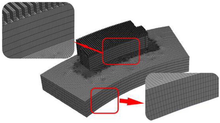
Mesh generation.
In order to prove that the results are independent of the mesh, the mesh independence analysis is carried out. The result is shown in Figure 7. The sealing performance parameters tend to be stable with the increase in the number of grid nodes. Only when the number reaches a certain value (about 80,000) in regular analysis can the calculation accuracy be guaranteed. The actual calculation mesh number (more than 400,000) is much higher, which can ensure the accuracy of the calculation.

Influence of mesh number on sealing performance.
Boundary conditions
For the boundary conditions, groove inlet is the high pressure side, which is external variable pressure and groove outlet is the low pressure side, which is the constant atmospheric pressure. The surfaces of gas film connected with rotating ring are rotational walls, and the surface connected with stationary ring is a static wall. The control equation satisfies the periodic boundary condition in the computation region:24,25
Γ1 and Γ2 are periodic boundary conditions, and the pressure and mass flow rate are equal.
The pressure is periodic, which is p(θ+ 2π/N g ) = p(θ).
Specific boundary conditions are shown in Figure 8.

Boundary conditions.
Results and discussions
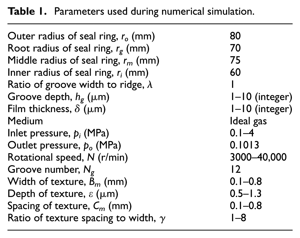
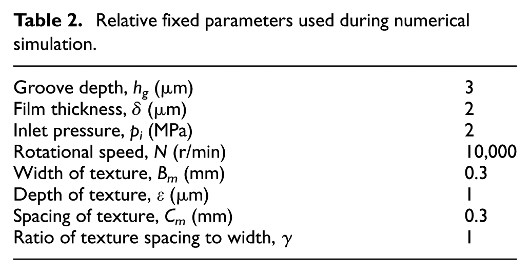
For systematic analysis of the performance of DGS with orientation texture, it is necessary to determine the range of fixed parameters and variable parameters, and they are listed in Table 1. In the following calculations, the relative fixed parameters are shown in Table 2. If there are no specific instructions, the parameters are taken as follows: λ = 1, hg = 4 μm, δ = 2 μm, pi = 2 MPa, and N = 10,000 r/min.
Parameters used during numerical simulation.
Relative fixed parameters used during numerical simulation.
Orientation texture selection
According to the direction of fluid flow and the principle of hydromechanics, the orientation textures are proposed, as shown in Figure 9.

Three types of texture: (a) cross structure and (b) parallel structure.
The related performance of the above-mentioned textures is shown in Figure 10. Both the opening force and the leakage rate of the parallel structure are larger than the cross structure under different rotational speeds, and both the leakage rates are within the allowable range. This is possible because the parallel structure promotes the characteristics of the bottom fluid extrusion effect. Therefore, the parallel structure texture is selected for further study.

Sealing performance comparison of different textures.
Simulation verification
In order to verify the correctness of the simulation method, the parameters in the related literature 26 were selected for calculation and comparison. The opening force Fo and leakage rate Q were taken as target variables. The results of comparison are shown in Figure 11, which show that Fo and Q in this study are in good agreement with the literature. This indicates that the simulation method is reasonable and feasible.

Opening force comparison with the study of Li et al. 26
Texture structure performance analysis
The parallel structure texture (TT-DGS) is selected as the research object, and the opening force and leakage rate are the two main objective factors of the sealing performance. Figure 12 shows the pressure distribution of TT-DGS under three film thicknesses. It can be seen that the smaller the film thickness, the greater the opening force, and the extrusion effect of pressure on the side of the groove is more obvious. This is consistent with the known law of DGS. The simulated results are shown in Table 3.

Pressure distribution under different film thickness: (a) TT-DGS (δ = 2 μm), (b) TT-DGS (δ = 3 μm), and (c) TT-DGS (δ = 5 μm).
Performance parameters of comparison.

T-DGS: T-groove dry gas seal; TT-DGS: T-groove dry gas seal with orientation texture.
As shown in Table 3, the opening force with texture has a significant improvement under three kinds of film thicknesses compared to that of non-texture one, and the smaller the film thickness, the more obvious the increase. Meanwhile, the leakage rate of TT-DGS is smaller than T-DGS. The lifting of opening force indicates that the orientation texture at the bottom of the groove has a remarkable effect on promoting gas flow and dynamic pressure. In general, the opening force and leakage rate of DGS synchronously increase or decrease. A possible reason for the phenomenon of the increased opening force with the decreased leakage rate is that the existence of the orientation texture enhances the ability of gas backflow and reduces the speed and quantity of leakage gas.
Comparative analysis of sealing performance
Figure 13 shows that the opening force and leakage rate of TT-DGS and T-DGS vary with increasing rotational speeds under different groove depths and film thicknesses. It can be seen that the opening force of both structures increases with decreasing film thickness or increasing rotational speed; when the film thickness δ = 2 μm, opening force decreases as groove depth increases and when δ≥ 3 μm, opening force increases as groove depth increases. The leakage rate increases with increasing film thickness, and when rotational speed increases, the leakage rate increases first and then decreases. Similarly, δ = 3 μm is the inflection point of the leakage rate, which is consistent with the variation trend of the corresponding opening force. The reason for the different regular trend of opening force and leakage is the existence of texture, which makes the micro-scale flow field of different film thicknesses and groove depths more complex when rotating speed changes; however, the overall effect still promotes the opening force.

Influence of rotational speed on opening force (pi = 2 MPa): (a) δ = 2 μm, (b) δ = 3 μm, and (c) δ = 5 μm.
Overall, the opening performance improvement of texture is obvious and it also has the advantage of reducing leakage. The opening force lifting effect of texture is better when with smaller film thickness and higher rotational speed. The rapid growth of opening force in small film thickness is critical to the stability of DGS.
Influence analysis of texture geometric parameters
The above researches indicate that texture geometric parameters have great effect on the sealing performance of TT-DGS. Therefore, this section will give detailed analysis.
Influence of texture depth
The influence of texture depth on sealing performance is shown in Figure 14(a). As the texture depth increases, the opening force increases and the leakage rate decreases. The increase in the depth means that the orientation area of gas increases, which enhances the orientation and extrusion effect, eventually presenting increasing opening force. There is a slight decrease in the leakage rate. The possible reason is that the increase in the texture depth increases the power loss resulting from larger micro-expansion cavities, making the velocity of leaking gas to decline. In combination with the above trend and considering the difficulty and cost of processing, the ideal range of the texture depth should be 0.9–1.2 μm.

Influence of texture geometric parameters on sealing performance: (a) texture depth (= 1, Bm = 0.3 mm, Cm = 0.3 mm); (b) texture width (= 1, ε = 1 μm); and (c) texture spacing (ε = 1 μm, Bm =0.3 mm).
Influence of texture width
The ratio of the texture width and space, γ, is 1, which represents that the texture width and space vary in equal proportion. As shown in Figure 14(b), the variation of texture width has little effect on sealing performance. In such situation, the texture area is invariant, which means that orientation area and effect of texture are invariant, thus both the opening force and the leakage rate do not vary obviously. It indicates that the texture area probably influences the sealing performance. The following study will give the detailed expression.
Figure 14(c) shows the sealing performance of the TT-DGS under various texture spacing with fixed texture width (Bm =0.3 mm). Based on this, both the opening force and the leakage rate decrease when the texture spacing increases. The increasing texture spacing means the decreasing texture area and the descending orientation area, which makes the extrusion effect and orientation effect to decrease accordingly. The decrease in the two effects will directly result in the reduction in the opening performance and leakage rate.
From Figure 14(a) and (b), it can be seen that the texture area has a direct impact on the sealing performance, which shows that the greater the area, the larger the opening force and leakage rate, and the leakage is within allowable range. In addition, considering the processing efficiency and cost, the texture area cannot be infinite, and the texture width and spacing should be based on the precision of the machining equipment.
TT-DGS performance analysis under different parameters
Geometrical parameters and operating parameters have great influences on the sealing performance of DGS. In this article, the effect of texture on the sealing performance is further analyzed by means of relative parameter variation.
By taking the above optimal texture as the research object, the opening force and leakage rate were selected as the main indexes and compared with the DGS without texture. As can be seen from Figure 15(a)–(d), the opening performance of texture is better than that of non-texture structure under different speeds, pressures, groove depths, and film thicknesses. The influence rules of different parameters are as follows: opening force and leakage increase with rising rotational speed or pressure; the increase in film thickness makes the leakage rate to increase and the opening force to decrease; and the opening force and leakage rate first increase and then decrease with increasing groove depth. The above conclusions fully prove the advantages of the orientation texture under different parameters, and the trend is consistent with the existing theory of traditional DGS. There is a certain groove depth range (2–4 μm for this research) which can obtain higher opening force along with lower leakage. Overall, the supercharging effect of texture is more significant under high speed, high pressure, and micro-scale.

Influence of different parameters on sealing performance: (a) rotational speed (pi = 2 MPa, δ = 2 μm, hg = 3 μm); (b) pressure (N = 10,000 r/min, δ = 2 μm, hg = 3 μm); (c) film thickness (N = 10,000 r/min, pi = 2 MPa, hg = 3 μm); and (d) groove depth (N = 10,000 r/min, pi = 2 MPa, δ = 2 μm).
Radial pressure and bottom velocity distribution
Figure 16(a) and (b) represents the fluid velocity distribution of non-texture and texture T-DGS, respectively. As shown in the figures, the extreme value of fluid velocity of non-texture structure is 115.8 m/s and for texture structure 131.9 m/s. This demonstrates that TT-DGS has better orientation effect. Further analysis shows that, for the flow streamline trend close to the bottom, TT-DGS has a better pump ability.

Fluid velocity distribution: (a) T-DGS and (b) TT-DGS (N = 10,000 r/min, pi = 2 MPa, δ = 2 μm, hg = 3 μm).
In order to further elaborate the effect of texture on orientation and supercharging, the radial pressure distribution of seal face is analyzed. As can be seen from Figure 17, the peak pressure area of TT-DGS is larger than T-DGS along the radial dimension. It shows that the existence of texture improves the area of high pressure on the sealing end surface, and it reveals the cause of the formation of opening force lifting effect of this texture.

Peak pressure of seal end face along with radial dimension (N = 10,000 r/min, pi = 2 MPa, δ = 2 μm, hg = 3 μm).
Laser machining method based on orientation texture
At present, the ideal method to process groove is by laser. In order to minimize the effect of roughness, after the laser texturing process is finished, the lapping method is generally used. However, the processing efficiency of this method is low and the processing cost is high. Based on the orientation texture model, laser machining technology can be used to realize the specific shape of texture in a certain order like along the scanning path. In this way, the uncertain influence of the random roughness on the flow of the groove bottom can be reduced. The controlling parameters of machining precision are focal length, step size, power, and frequency. After the focal length is adjusted, both the initial rough engraving and the fine carving should be conducted, in order to ensure low roughness and good randomness of the bottom. The initial engraving with high power, large step size, and low frequency is efficient. A fine engraving process with low power, small steps size, and high frequency is carried out. The details of this processing method, which is efficient and cost-saving, are shown in Figure 18(a).

Basic steps of DGS laser processing: (a) traditional laser engraving and (b) laser engraving based on texture structure.
When processing the orientation texture by laser, fixed parameters can be used for continuous engraving, because the groove bottom itself has certain direction and regularity. This micro-texture can effectively counteract the effect of random roughness. This method with details shown in Figure 18(b) is more convenient and efficient.
Conclusion
A type of TT-DGS is presented in this article. The influences of both geometric and operating parameters on sealing performance, including the opening force and leakage rate, are systematically studied through numerical simulations. The following conclusions summarize the outcomes of the investigation:
Orientation texture on groove bottom of T-DGS can improve the sealing performance. This design can improve the opening force and reduce the leakage rate in a certain design. Opening force increases with increasing rotational speed, medium pressure, and texture area, which demonstrates that TT-DGS is more suitable for high-speed and high-pressure conditions on the premise that the leakage rate is not beyond the international standard. TT-DGS can receive excellent sealing performance especially in micro-scale working conditions, which is conducive to improving the sealing stability.
Both the groove depth and the texture depth give optimal values with which we can obtain higher opening force along the lower leakage rate. For the parameters in this study, the corresponding optimal values are about 2–4 μm and 0.9–1.2 μm, respectively.
Based on the orientation texture design, the LST of DGS does not need fine processing for groove bottom, such as lapping and polishing. It can simplify the grooving process, improve the efficiency, and reduce the cost.
In the calculation, the effect of slip flow was ignored, which would cause certain error in the calculation of specific performance parameters, but would not affect the comparative analysis results of the parameters. In view of the relational model of texture direction and flow field direction established in this article, two micro-texture structures are initially modeled according to the general direction of flow field. Systematic and detailed research based on the model is still absent and confirmatory experiments are also necessary, which are the future works of our team.
Footnotes
Handling Editor: Noel Brunetiere
Declaration of conflicting interests
The author(s) declared no potential conflicts of interest with respect to the research, authorship, and/or publication of this article.
Funding
The author(s) disclosed receipt of the following financial support for the research, authorship, and/or publication of this article: The research was financially supported by the National Natural Science Foundation of China (grant nos 51741504 and 51805199) and the Brand Professional Construction Project of Jiangsu Universities (grant no. PPZY2015C214).