
Abstract
The gas film of the carbon dioxide (CO2) spiral groove dry gas seal (S-DGS) is less than 3 μm during the startup process, and its opening stability is directly related to the operating performance of S-DGS. The finite difference method is employed to solve numerically the pressure distribution of S-DGS considering the slip flow and the real gas effect. The influence of both effects on the startup characteristics of S-DGS is discussed at different structural parameters. The results show that the slip flow effect inhibits the opening ability of CO2 S-DGS, whereas the real gas effect enhances its opening ability. Within the range of working conditions investigated, the seal processes a lowest startup rotational speed when the spiral angle is 7.5°, and the highest gas film stiffness occurs at small spiral angle when the film thickness is 0.6 μm. However, the relationship between groove number and gas film stiffness is complex which relates to the balance film thickness of the startup process. A higher opening ability can also be achieved by reasonably increasing the balance coefficient.
Introduction
The CO2 spiral grooves dry gas sealing (S-DGS) has a good sealing effect, 1 and it is often employed for the centrifugal compressor in the field of supercritical CO2 turbine power generation 2 and urea production. In the startup process of S-DGS, the sealing clearance increases from zero to stable working film thickness (generally 3–5 μm). This stage is essential for S-DGS to enter a stable operation state. A good opening ability and gas film stability can provide a solid basis for the reliable startup of S-DGS. In the early startup period, the film thickness of the S-DGS is close to the average molecular freedom path (AMFP) of lubrication gas, showing noticeable slip flow effect. When the pressure of the sealing medium is relatively high and the rotating speed of the principal axis increases gradually, the flow field on the end face of S-DGS, with a small clearance, may generate a noticeable pressure jump. As a result, the CO2 real gas effect sensitively related to the pressure is highlighted gradually. Therefore, two special effects must be considered in the startup stage of S-DGS.
Compared with the stable operation stage, although the startup procedure of S-DGS lasts for a short period, the relevant lubrication mechanism is complicated and involves many influencing factors. These features have attracted the attention of many scholars. They have discussed the startup performances of S-DGS from the perspectives of the texture end face of seal ring, 3 surface structural parameters, 4 operation parameters, 5 and surface morphology of end face of seal ring, 6 achieving a series of guiding research fruits. The clearance in the startup process of S-DGS is expanded. The clearance gradually expands when startup of S-DGS. The ratio between the mean free path of lubricating gas molecules and the gas film thickness could be used to determine the gas flow area on the end face. 7 At present, the application of this characteristic parameter mainly concentrates on studies on the stable operation stage of S-DGS. Ruan, 8 Yin and Peng, 9 and Zhao et al. 10 solved the modified Reynolds equation considering the slip flow effect using the finite element method. They verified that the S-DGS had a noticeable slip flow effect under working conditions of low pressure and low velocity. Zhang 11 and Wang 12 solved the modified Reynolds equation considering the slip flow effect using the finite difference method and analyzed the sealing performance of S-DGS influenced by the slip flow effect. Fairuz and Jahn, 13 Du et al., 14 and Shen et al. 15 investigated the influencing laws of the real gas effect of CO2 on steady-state performances (e.g., opening force and leakage rate) of S-DGS by focusing on the advancement of supercritical CO2 cycle power generation. Based on Muijderman narrow groove theory, Song et al. 16 analyzed the modified governing equation of gas film pressure considering the real gas effect and the slip flow effect. They pointed out that the slip flow effect was noticeable under low pressure, and the real gas effect was more significant under high pressure.
It can be concluded by reviewing the literature that the published reports of dry gas seal with consideration of slip flow and real gas effect mainly focus on the stable operation stage of S-DGS. However, the application of S-DGS gradually tends to a high-pressure environment, and the slip flow effect in the clearance of S-DGS and real gas effect of lubrication gas shall not be ignored. In addition, S-DGS may go through a low-speed and high-load (high closing force caused by high inlet pressure) stage during the early startup period. If the end face of seal ring cannot be separated quickly, it might directly influence the stable operation of S-DGS. Thus, the startup characteristics of S-DGS considering the slip flow effect and the real gas effect have to be further discussed. Based on the quasi-steady state calculation, the virial state equation and the Fukui-Kaneko classical boundary velocity slip flow model (F-K slip flow model) are selected to characterize the real gas behavior of CO2 and the gas film slip flow phenomenon, respectively, in this study. The film thickness value when the contact force of the sealing ring surface turns zero is used as the gas film thickness of critical separation, and the influence of real gas and slip flow effects on the startup performance of S-DGS is analyzed at different sealing ring structure parameters. The influence of gas film temperature at the seal clearance inlet on the startup characteristics and the change laws of the viscous shear thermal during startup process are discussed, which provide some theoretical guidance for the application engineering design of S-DGS under high pressure condition.
Determination of critical opening film thickness
The typical structure of S-DGS is shown in Figure 1. In the startup process, lubrication gas of the end face is pumped into the sealing ring surface continuously, and the gas film thickness increases from zero to several micrometers gradually. Meanwhile, the S-DGS changes from the contact state to the non-contact state.

The typical schematic diagram of the S-DGS.
In the startup process of S-DGS, the seal gas pressure has been applied to the boundaries of S-DGS. Gases penetrate the clearance of asperity of sealing rings, and forming the gas film. The contact stage of the S-DGS startup includes the mixed friction state and solid contact state. In this case, the end face’s opening force is composed of the contact force of solid and gas film force, which is balanced with the closing force. The closing force of S-DGS is composed of the elastic force of elastic component (spring or corrugated pipe) and gas static pressure at the balanced radius. And it is generally kept constant. In the startup process, the gas film force increases quickly with the increase of rotating speed, and the sealing clearance expands gradually. At the same time, the contact area of asperity on the end face narrows, and the end face of the sealing ring is separated gradually. When the contact force of the end face decreases to zero or approaches zero, the end face is separated completely by gases. At this moment, the dynamic and static rings of S-DGS are separated completely, thus opening the end face. In this study, the contacting force of end face reaching zero or approaching zero was viewed as the judgment reference to the opening of S-DGS. The instant gas film thickness when the end face transits from the contact state to the non-contact state is defined as the opening film thickness of S-DGS.
The contact of surface uses the classical GW model to determine the solid contact force among end face of seal rings. In other words, the end face asperity of dynamic and static ring are hypothesized spherical crown-shaped structures, with height conforming to the Gaussian distribution laws. The S-DGS is chosen as a research object, and the contact force between the dynamic and static ring of the S-DGS is calculated as follows 17 :
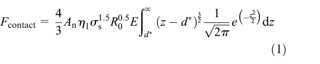
where An is the nominal contact area, η1 is the area density of asperity, σs is the standard deviation of height distribution of asperities on the rough surface of the stationary ring, R0 is the peak radius of curvature of asperity, E is the integrated elasticity modulus, and d* is the distance from the smooth rigid plane to the mean height plane of asperity.
The morphological parameters of the contact model are collected from Etsion and Front. 18 They are widely used by Ruan, 19 Xu et al., 20 and other scholars. Sealing ring parameters of Ruan 19 were chosen. The relationship between the gas film thickness of S-DGS and contact force of the end face can be disclosed from equation (1), as shown in Figure 2.
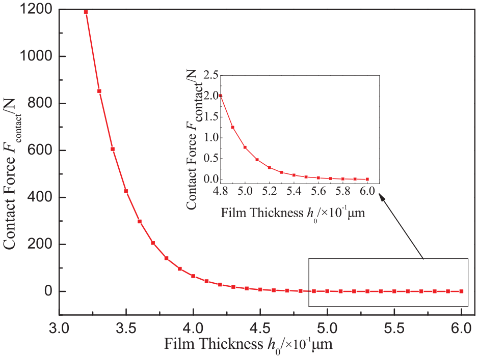
Relationship between film thickness and contact force.
The contact force among the end face of sealing ring decreases when they are separated gradually (increase in gas film thickness). The reason is that the number of contact asperity between dynamic and static rings decreases with the increase of gas film thickness and deformation of these asperity is relieved. When the gas film thickness (h0) is 0.52 μm, the contact force (Fcontact) is 0.28 N, and the contact force tends to be zero. Therefore, no contact is between the end face of sealing ring, and the end face are separated completely.
Pressure governing equation of lubrication gases
Real gas characterization model
The real gas state equation can be expressed as follows 21 :

where p is the gas pressure, Vm is the molar volume of gas, M is the molar mass of gas, Z is the gas compressibility factor, Rr is the general gas constant, T is the gas temperature, and ρ is the gas density.
From the real gas state equation, when Z = 1, equation (1) is the ideal gas state equation. The compressibility factor Z expresses the density deviation degree of real gas relative to ideal gas. And it is related to gas pressure and temperature.
Under the working conditions of pressure (0.1–10 MPa) and temperature (400 K) of CO2. It can be seen from the Figure 3 that the accuracy of Virial equation is the highest, among four real gas state equations, 22 include Van Der Wall (VDW) equation, Redlich Kwong (RK) equation, Soave Redlich Kwong (SRK) equation, and Virial equation. The VDW equation, RK equation, and SRK equation belong to the cubic equation of state, which are transformed from the real gas state equation, they are the cubic expansion of the compressibility factor Z. while the Virial equation belongs to the analytical state equation, which is a multiple expression of pressure p and temperature T. The relative error EZ (EZ = (ZNIST − Z)/ZNIST × 100%) is used to express the deviation between the calculation results of the real gas state equation and the NIST database. 23 The average deviation between the calculated results of Virial equation and NIST database is 0.056%, and the maximum deviation is 0.11%. In this study, the real gas behaviors of CO2 were expressed by the Virial ternary truncation, and the expression of Z is as follows:

where Bv and Cv are called the second virial coefficient and the third virial coefficient, and their values are compared with the temperature Tr and eccentricity factor ε.

Verification of real gas state equation.
Pressure governing equation
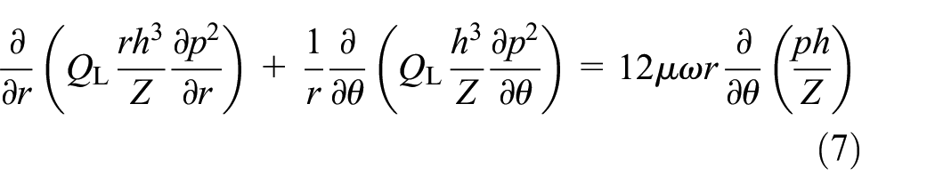
Fukui-Kaneko analyzed ultrathin gas film lubrication based on the linearized Boltzmann equation, 24 thus the Reynolds equation with consideration to velocity slipping flow effect of boundaries (F-K slipping flow model) is employed in this study.

where QL is the flow factor, and the value is as follows:

Figure 4 shows the opening force curve of several slip flow models with gas film thickness variation. It can be seen from the Figure 4 that the calculation results of the F-K slip flow model are closest to the experimental data of Jiang. 25 And the maximum deviation is 0.47%, indicating that the F-K slip flow model is more suitable for this working condition. F-K slip flow model has been widely applied by scholars.19,26

Verification of slip flow model.
Meanwhile, considering the influences of the real gas effect and the slip flow effect at the same time, the pressure governing equation of gas film in the startup process can be expressed as follows:

The pressure governing equation of steady-state gas film ignoring the time term as follows:
The boundary conditions was used to solve the pressure governing equation:

The opening force of end face is obtained:

The closing force of the sealing ring is composed of backpressure acting force on the static ring and spring force:

Axial gas film stiffness of the seal ring:

The heat of end face are generated by the gas film in the spiral groove area and the seal dam area due to viscous shear 27 :

Where pi is the outlet pressure, po is the inlet pressure, psp is the spring specific pressure, ro is the outer diameter of sealing ring, ri is the inner diameter of sealing ring, rb is the balance radius of the sealing ring, Ng is the number of seal ring grooves, μ is the gas viscosity, ω is the rotation speed, h0 is the gas film thickness, he = h0 + h0/(1 + γ) is the equivalent film thickness, and γ is the ratio of spiral groove to the platform.
Verification of developed numerical method
Numerical calculation
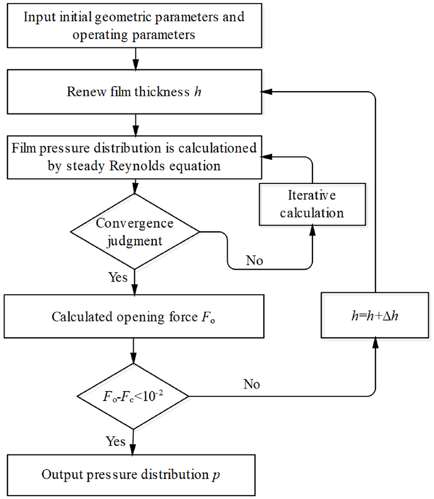
Based on the idea of quasi-steady-state calculation, the time term in equation (6) was neglected in the calculation process. The inertia force and external disturbance incentives in the S-DGS startup process are not considered temporarily. All instant moments during startup process of the sealing ring are viewed as the force balanced state (i.e., opening force is equal to the closing force Fo = Fc). The discretized expressions of equation (7) obtained by the finite difference method (FDM) is shown as follows 28


The flow field characteristics among end face of seal ring were calculated through numerical iteration of MATLAB software programming. The numerical calculation process is shown in Figure 5.
Flow chart for numerical calculation.
Verification of developed numerical method
To elaborate accuracy of the calculation program of S-DGS flow field characteristics during startup process, Z was set 1 through a case study based on S-DGS parameters in Ruan. 19 The time-mean of the film thickness curve was used as the verification objective and a group of time nodes were chosen and converted into the rotating speed. The balance film thickness during startup process of S-DGS was calculated through numerical analysis (Figure 6). The numerical calculated results of balance film thickness during startup process of S-DGS (accelerating stage) are consistent with values in references, and the low-speed startup process has some deviation, which is caused by different evaluation standards of opening film thickness. In Ruan, 19 the opening film thickness is defined as 3.7 times the comprehensive deviation of seal ring roughness. In other words, the opening film thickness is determined at 0.37 μm when σs = 0.1. According to variation laws of contact force of end face with film thickness in Figure 2, the opening film thickness was defined as 0.52 μm, which deviates from the opening film thickness to some extent. This is the major reason for the great deviations in the low-speed regions in Figure 6. As the speed of the main shaft increases gradually, the deviation between numerical calculation results and values in references decreases gradually after the end face of seal rings are separated completely. When the rotating speed is N = 3600 r/min, the deviation is only 0.18%, indicating that the proposed calculation program is feasible.

Balance film thickness during startup process of S-DGS.
Utilized parameters in calculations
Calculation parameters of S-DGS
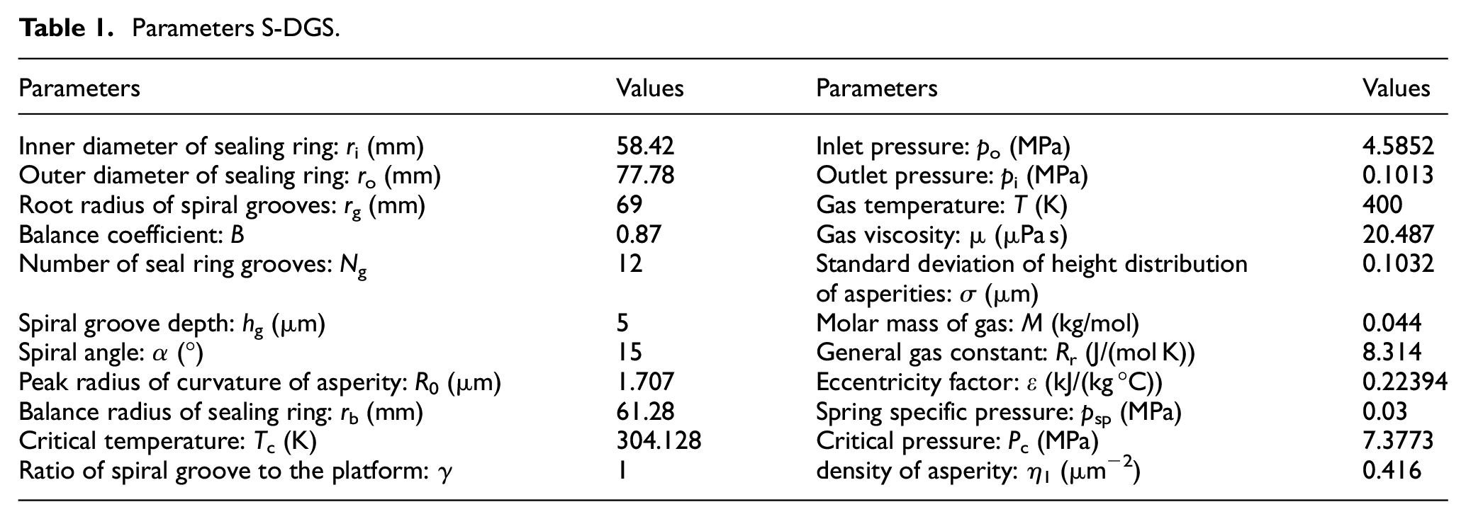
Based on classical structures in the S-DGS 29 field (Table 1), influences of the slip flow and real gas effect on startup characteristics of CO2 S-DGS were discussed using Etsion and Front 18 morphological parameters of the end face sealing ring.
Parameters S-DGS.
Relative errors
This study intuitively reflects the influence of the slip flow effect and the real gas effect on the startup characteristics of the S-DGS. The following relative errors are defined: E
1 = (the results of real gas and slipping flow − the results of ideal gas and slipping flow)/the results of ideal gas and slipping flow × 100%. E
2 = (the results of real gas and non-slipping flow − the results of ideal gas and non-slipping flow)/the results of ideal gas and non-slipping flow × 100%. E
3 = (the results of ideal gas and slipping flow − the results of ideal gas and non-slipping flow) / the results of ideal gas and non-slipping flow × 100%. E
4 = (the results of real gas and slipping flow − the results of real gas and non-slipping flow)/the results of real gas and non-slipping flow × 100%.
Numerical results and discussions
According to the above determination of critical opening film thickness for the studying S-DGS was defined as 0.52 μm. The opening speed refers to the rotating speed of the main shaft when the gas film thickness equals the opening film thickness, which also refers to the critical separation speed of seal rings.
The opening speed
Effects of structural parameters on opening speed
The influence of slip flow effect and real gas effect on the opening speed of S-DGS with different sealing structural (spiral angle (α), groove depth (hg), groove number (Ng), and balance coefficient (B)) were compared (Figure 7). According to the comparison between the non-slipping-flow ideal-gas model and the slipping-flow ideal-gas model and the comparison between the non-slipping-flow real-gas model and the slipping-flow real-gas model, the slip flow effect increased the opening speed of S-DGS, weakening the opening capacity. The essence of the slip flow effect can be understood as reduced viscosity of the gas. The lower viscosity leads to the weaker dynamic pressure effect. When the gas film thickness reaches the opening film thickness, the slip flow effect needs a higher opening speed compared to the non-slipping flow model to maintain the force balance of the float ring and offset the reduced gas film force caused by slip flow effect.
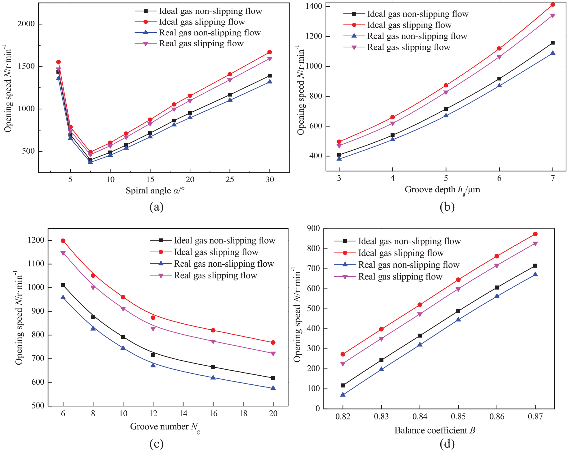
The influence of the slip flow effect and the real gas effect on startup rotational speed at different structure parameters: (a) opening speed (N)–spiral angle (α), (b) opening speed (N)–groove depth (hg), (c) opening speed (N)–groove number (Ng), and (d) opening speed (N)–balance coefficient (B).
Similarly, the non-slipping-flow ideal-gas model and the non-slipping-flow real-gas model were compared. The slipping-flow ideal-gas model and the slipping-flow real-gas model were also compared. In four structure cases, the opening speed decreases because of the real gas effect of CO2, which increases the opening capability. The reason is that the real gas effect of CO2 can improve gas film force effectively. 15 The slip flow effect and the real gas effect of CO2 have opposite influences on opening speed. Under current research conditions, the slip flow effect dominates in increasing opening speed.
The influence laws of slip flow effect and real gas effect on opening speed of S-DGS under different spiral angle, but the same other parameters are shown in Figure 7(a). With the increase of spiral angle, the opening speed of four calculation models presents an approximately a V-shaped variation trend (i.e. the lowest opening speed is obtained at α=7.5°), indicating that opening ability corresponding to the opening film thickness increases first and then decreases with the increase of spiral angle. The main reason is that the radial flow resistance of lubrication gas in the sealing clearance decreases and the pump-in volume of gas increases with the increase of spiral angle, accompanied by lifting pressure in the groove area. As the spiral angle continues to increase, the gas flow distance from the entrance of spiral grooves to the groove root is shortened, and the compression of lubrication gas in the limited space is weakened, thus decreasing dynamic pressure effect at the groove root and generating relatively low gas film pressure on the surface. When the spiral angle increases from 3.5° to 30°, the influences of the real gas effect and the slip flow effect of CO2 on opening speed increase first and then decrease. Specifically, the influence error (E2) of the real gas effect under non-slipping flow state increases from −5.50% at α = 3.5° to −7.17% at α = 10° and then decreases to −5.24% at α = 30° (negative indicates that the real gas effect decreases opening speed under non-slipping flow state). The influence error (E4) of the slip flow effect of the real gas state increases from 8.40% to 24.94% and then decreases to 20.92%.
The influence of slip flow effect and real gas effect on opening speed with groove depth are shown in Figure 7(b). Opening speed presents a monotone increasing trend in the studying range of groove depth, indicating that S-DGS has relatively weak opening ability in the large range of groove depth. The reason is that the minimum groove depth is far higher than the thickness of the gas film. For example, groove depth ratio (hg/h0) when hg = 3 μm is approximately 5.77, thus resulting in the weak staircase effect in the groove area of S-DGS and restricting the generation of the dynamic pressure effect. Furthermore, the lubrication gas flow in the sealing clearance is hindered to some extent when hg/h0 is relatively high, further weakening the gas film’s dynamic pressure effect. When groove depth increases from 3 to 7 μm, the man values of influence errors of the real gas effect (E1 and E2) and the influencing errors of the slip flow effect (E3 and E4) were −5.31%%, −6.32%%, 18.04%, and 18.91%, respectively. E3 and E4 are significantly higher than E1 and E2, demonstrating that, under current working conditions, the flow field in the sealing clearance is mainly influenced by the slip flow effect, whereas the real gas effect does not take the dominant role.
Influence laws of slip flow effect and real gas effect on opening speed with the groove number (Ng) are shown in Figure 7(c). The opening speed decreases with the increase of Ng, and the reduction trend generally decreases in the large range of Ng. The reason is that, within the studying range of Ng, the pump-in channel of lubrication gas increases with the increase of Ng, and the pressure-increasing effect of lubricating gas in the groove is improved, thus enabling to form more high-pressure regions and finally increasing the gas film force. Additionally, influencing errors of the real gas effect and the slip flow effect on the opening speed show a weak uprising trend with the increase of Ng. In the range of 6 ≤ Ng ≤ 20, E1 and E2 are increased by 1.69% and 1.96%, whereas E3 and E4 are increased by 3.71% and 3.92%, respectively. The calculated results of the non-slipping-flow idea-gas model and the slipping-flow real-gas model were compared. The opening speed of the slipping flow -real gas model is increased by 15.45% compared with that of the non-slipping-flow idea-gas model, which is sufficient to prove the necessity of considering the influences of the real gas effect and the slip flow effect simultaneously under current conditions.
Influence of the real gas effect and the slip flow effect on opening speed under different balance coefficient are shown in Figure 7(d). In this study, the balance coefficient was defined as B =( ro 2 − rb 2 )/(ro 2 − ri 2 ). Its physical essence is the ratio of seal gas pressure action specific pressure (pe) to seal gas pressure (p). 30
Opening speed increases with the increase of the balance coefficient. A relatively high balance coefficient corresponds to a small balance radius, and the back pressure force produced by the inlet pressure (po) may be increased, increasing the closing force. To balance the closing force, the rotating speed has to be increased to generate an extra dynamic pressure to realize the force balance of the float ring. Taking the slip-flow real-gas model as an example, the balance coefficient (B) increases from 0.82 to 0.87. In other words, the balance radius decreases from 62.35 to 61.28 mm, and the opening speed increases by 265%. Therefore, the opening speed is extremely sensitive to changes in balance coefficient, and S-DGS with a low balance coefficient has a stronger opening ability under the same conditions. Influencing errors of the real gas effect and the slip flow effect on opening speed are negatively related to the balance coefficient. Increasing the balance coefficient brings an increase in opening speed. Although it can increase gas film pressure for the real gas model and the slip flow model, it also increases the dynamic pressure effect of gas film for the ideal gas model and non-slipping flow models.
Effects of medium pressure on opening speed
The influence laws of the slip flow effect and the real gas effect on the opening speed of S-DGS under different medium pressures can be shown in Figure 8. The medium pressure is positively related to the opening speed. The E1 and E2 of the opening speed in the slipping flow model and the non-slipping flow model are −4.40% and −5.94%, respectively. E3 and E4 of opening speed in the real and ideal gas models are 17.78% and 19.16%, respectively. Influences of the real gas effect on the opening speed in the slipping flow model are weaker than those in the non-slipping flow model. Furthermore, the influences of the slip flow effect on the opening speed in the real gas model are also weakened compared with those in the ideal gas model. The reason is that, for S-DGS used in CO2, the real gas effect can improve the gas film pressure on the end face effectively, and the AMFP of CO2 decreases, thus intensifying differences between AMFP and opening film thickness. Thus, the slipping flow weakens accordingly. In the slipping flow model, the slip flow effect is macroscopically equivalent to reduced viscosity of gases, 16 weakened viscosity shearing effect, and decreased hydrodynamic effect of gas. Consequently, the gas film pressure declines, and the intensity of real gas effect is proportional to pressure. Therefore, the influencing error of the real gas effect corresponding to the slipping flow model is lower than that in the non-slipping flow model.

The influence of slip flow and real gas effects on startup rotational speed at different medium pressures.
Analysis of thermal effect during startup
Based on the assumption of isothermal model and considering the real gas effect, the influence of inlet temperature of gas film on the seal startup performance is investigated, and then the heat generation between the end face of seal ring at the startup stage is analyzed, which are shown in Figure 9. It can be seen that the opening speed in ideal gas and real gas models decrease with the increasing of inlet temperature. This is because the higher the temperature, the greater the CO2 viscosity, which results in a greater viscous shear and dynamic pressure effect in the sealing clearance, and then the opening ability of gas film will be improved (i.e., the opening speed is lowed). However, with the increasing of temperature, the deviation of opening speed between real gas and ideal gas becomes smaller. This is because the higher temperature decreases the deviation between the gas compressibility factor and 1, and the density of CO2 real gas is more close to that of CO2 ideal gas, that is, the degree of dynamic pressure effect in real gas model is similar with that of ideal gas at high temperature. Figure 9(b) illustrates that the viscous shear heat between both sealing face of S-DGS increases nonlinearly with the increasing of balance gas film thickness. For the same film thickness, the greater the pressure, the higher the heat generated. The growth rate of viscous shear heat is more obvious at larger balance gas film thickness. This is mainly due to the fact that higher pressure and larger balance gas film thickness are all contribute to the increasing of balance rotational speed, which plays a dominant role in the generation of viscous shear heat.

Influence of thermal effect on startup performance: (a) opening speed (N)–gas temperature (T) and (b) heat (Q)–gas film thickness (h0).
Non-contact gas film stiffness during startup stage
Non-contact opening gas film stiffness
The variation of gas film stiffness in the non-contact startup stage under different structural parameters are shown in Figure 10. Generally speaking, the gas film stiffness increases first and then decreases from the opening of S-DGS to stable film thickness. When the spiral angle is large, the maximum stiffness occurs at the place with high balance film thickness, and the stiffness changes less. In Figure 10(a), the gas film stiffness in the non-contact startup stage changes the most when the spiral angle is 3.5°. The gas film stiffness at 0.6 μm of film thickness can be increased by 43.52% compared with the initial opening moment (point with opening film thickness) and the corresponding balancing speed is 1678 r/min. Then, it decreases quickly by 65.43% when the balance film thickness is 3 μm, and the corresponding balancing speed is 64414 r/min. When the spiral angle is 30°, the rising amplitude of gas film stiffness in the non-contact startup stage is relatively gentle. In a word, the large spiral angle can weaken the fluctuation of gas film stiffness with increased balance film thickness.

The influence of the slip flow effect and the real gas effect during startup rotational speed at different structure parameters: (a) gas film thickness (h0)–spiral angle (α), (b) gas film thickness (h0)–groove depth (hg), (c) gas film thickness (h0)–groove number (Ng), and (d) gas film thickness (h0)–balance coefficient (B).
The variation of gas film stiffness under different groove depths with the balance film thickness are shown in Figure 10(b). Given the weak staircase effect between end face of S-DGS and an obvious low-pressure region formed near the leeward side of the spiral groove under high groove depth, the force and stability of gas film are weakened. Therefore, the gas film stiffness corresponding to any balance film thickness is negatively related to groove depth. Given a small groove depth, the startup stage of S-DGS has obvious high-stiffness regions. However, the variation of gas film stiffness with the balance film thickness becomes increasingly gentle as the groove depth further increases. Its gap with the gas film stiffness in the stable operation stage (working film thickness) narrows accordingly, revealing that, within the discussed range of groove depth, the gas film stability from opening to the stable operation of S-DGS has a good transition process when the groove depth is relatively high.
The relation between the gas film stiffness and the groove number in the non-contact startup stage is shown in Figure 10(c). In the early startup stage, gas film stiffness is negatively related to the groove number when the film thickness is fixed. Such phenomenon is pronounced near the critical separation state (h0 = 0.52 μm). The gas film stiffness decreases when the balance speed of S-DGS is relatively low in the early startup stage under a high groove number. Within the chosen working conditions in this study, the relation between gas film stiffness and groove number in the late non-contact startup stage turns opposite that in the early stage. In other words, the gas film stiffness is positively related to groove number when the gas film thickness is fixed. Given that the clearance of end face approaches the working gas film thickness in the late startup stage, the gas film stiffness is increased because of the high pumping capacity under the high groove number. At the same time, the fluctuation of S-DGS with gas film thickness under the high groove number in the late stage is far lower than that in the early startup stage. For example, the clearance of end face increases by 0.52–3 μm when there are 20 spiral grooves. The maximum growth amplitude of gas film stiffness in the early startup stage is 54.75%, and it decreases to 13.47% in the late stage. To consider gas film resistance to external interferences and the steady transition of S-DGS from opening to the operation stage of gas film stability, choosing 10–12 within studying working conditions is recommended.
The variation of gas film stiffness in the non-contact startup stage with balance coefficient is shown in Figure 10(d). The gas film stiffness increases and then decreases with the increase of balance film thickness when the balance coefficient is fixed. The reason is that, in the early startup stage of S-DGS, the strengthened dynamic pressure effect caused by increasing rotating speed takes the dominant role, and gas film stiffness increases gradually as the startup process continues. In the late startup stage, increasing film thickness inhibits the generation of the dynamic pressure effect to some extent, and the stiffness changes caused by film thickness take the dominant role. As a result, the gas film stiffness decreases with the increasing rotating speed and tends to be stable. Under working conditions, the maximum gas film stiffness occurs at a place with a balance coefficient of 0.87, a film thickness of 1.8 μm, and a rotating speed of 4206 r/min.
Effects of medium pressure on gas film stiffness
The variation of opening gas film of S-DGS with balance gas film thickness under different medium pressures are shown in Figure 11. All medium pressures achieve the maximum gas film stiffness when the balance gas film thickness is 1.5–2 μm in the transition process from opening gas film thickness to the working gas film thickness. Furthermore, the S-DGS has obvious characteristics of high-stiffness opening with the increase of medium pressure. The growth rate of gas film stiffness increases more and more obviously, it mainly attributed to the distribution of high gas film pressure caused by high medium pressure and corresponding high balance speed. Under the same medium pressure, the stability of S-DGS in the middle and late startup stage is superior to that in the early stage. The reason is that although gas film thickness in the middle and late startup stage is higher than that in the early stage, strong dynamic pressure effects are produced in the clearance of end face as a response to the high balance speed in the middle and late stage.

Gas film stiffness at different medium pressure.
Opening modes of S-DGS
Under working conditions, opening speed is extremely sensitive to the changes of the balance coefficient. Considering the slip flow effect and the real gas effect simultaneously, the variation of opening speed (N) with medium pressure (po) under different balance coefficients was discussed, aiming to optimize the opening capability of S-DGS. Results are shown in Figure 12. Under a high balance coefficient, the opening speed increases with the increase of medium pressure, showing that the higher medium pressure needs higher opening speed. As the balance coefficient decreased, the growth rate decreased, and the opening speed presented an inverted V-shaped variation trend. Finally, opening speed showed a monotonous decreasing trend under a low balance coefficient. Because the opening force proportion of static pressure increases under a small balance coefficient. And the opening force proportion of dynamic pressure decreases. So the opening speed decreases gradually. With the gradual reduction of the balance coefficient, even the opening speed is zero. Dynamic pressure and static pressure mixing opening will change to static pressure opening. In other words, S-DGS is opened by the pure static pressure of fluid under zero rotating speed.

Relation between rotational speed and medium pressure at different balance coefficients.
Within the ranges of B ≤ 0.8165 and po ≤ 10 MPa, there is some specific medium pressure for specific balance coefficient, it is called static pressure opening. In other words, poor sealing may occur when the range of B ≤ 0.8165. So the low balance coefficient and medium pressure correspond to the low opening speed. The static pressure of opening decreases with the decrease of the balance coefficient, and it is only 0.289 MPa when B = 0.6. Under this pressure, the end face can be separated at 0 rpm. To avoid static pressure of opening, that is, poor sealing, the balance coefficient and opening speed must be selected according to the medium pressure.
Conclusions
The slip flow effect and the real gas effect positively influence the opening speed of S-DGS. In other words, the opening capacity is strengthened by the real gas effect, but the slip flow effect can inhibit the opening capacity.
Within the working conditions, opening speed can be decreased by decreasing spiral angle and groove depth and increasing the groove number reasonably. However, influences of opening speed on the gas film stiffness are related to the balance gas film thickness.
The smaller balance coefficient and medium pressure bring higher opening capacity. The static pressure opening under smaller balance coefficient, which is positively related to the balance coefficient. As a result, it realizes the pure static pressure opening of S-DGS and causes static leakage of the seal. Thus, the balance coefficient and the opening speed must be selected reasonably according to the pressure of sealed media.
In the startup process of S-DGS, the research of multi-field coupling considering gas various real effects, gas film thermal effects, and sealing ring heat transfer will be the focus of future work.
Footnotes
Handling Editor: Chenhui Liang
Author contributions
QD and PS conceived and designed the research. HX analyzed the data. WM and XS conducted the theory. QD wrote the manuscript. PS reviewed and edited the manuscript. All authors reviewed the manuscript. All authors have read and agreed to the published version of the manuscript.
Declaration of conflicting interests
The author(s) declared no potential conflicts of interest with respect to the research, authorship, and/or publication of this article.
Funding
The author(s) disclosed receipt of the following financial support for the research, authorship, and/or publication of this article: This research was funded by Special Youth Fundamental Research of Yunnan Province (Grant No. 202101AU070019), Talent Training Project of Kunming University of Science and Technology (Grant No. KKZ3202005059).