
Abstract
In this article, a novel rollover prediction algorithm is developed for application on vehicles with large lateral velocity and high center of gravity. Lateral energy is the direct cause of rollover. Rollover prediction model is proposed by taking full account of the impact of the pavement, tire, and suspension and realizes the estimation of the vehicle lateral energy. By calculating the ratio of real-time lateral energy reserve and rollover threshold, the degree of rollover risk is obtained. The double-shift experiment and the Fishhook experiment are performed to verify the accuracy and suitability of the proposed model, and the proposed prediction is 0.2 s ahead of the actual liftoff situation and 0.45 s ahead of the actual rollover situation; therefore, the proposed rollover model can be regarded as an effective method.
Keywords
Introduction
According to statistics from the Traffic Management Bureau of the Ministry of Public Security, by the end of 2016, the number of motor vehicles in China reached 290 million, of which 194 million were cars and 360 million motorists were drivers, of which more than 310 million were motorists. 1 However, the number of casualties caused by traffic accidents continues to increase. The number of people killed and injured in traffic accidents in China has been ranked first in the world for 10 years. The number of accidents accounts for only 1.9% of the world’s total, whereas the death number accounts for 15% of the world’s total. However, the accident of rollover has not received due attention. According to statistics, the degree of harm caused by vehicle rollover accidents is only seconds to the crash accident. The number of casualties caused by rollover accidents in the United States accounted for 35% of vehicle accidents. 2
In the rollover mode, the lateral acceleration of the vehicle increases sharply. The tire is the only contact medium between the road surface and the vehicle. It has longitudinal, lateral, and vertical coupling motions and has complex nonlinear characteristics. The accuracy of tire model and suspension model is the core of the rollover warning. After thorough in-depth theoretical and experimental research, Professor Pacejka reduced the tires to a “string” structure and established a very famous “Magic Formula” with Bakker. 3 Svendenius and Gäfvert 4 of Lund Science and Technology studied the mechanical properties of tires under compound sliding conditions based on brush model, in consideration of the anisotropy of the tire, the difference in stiffness and friction coefficient, as well as the deformation of the carcass and the roll of the tire; the expressions of the longitudinal force, the lateral force, and the positive moment were finally established and verified by a large number of experiments.
J Preston-Thomas and JHF Woodrooffe developed a set of stability control and alarm systems that use the lateral-load transfer ratio (LTR) as the vehicle’s rollover criteria. The most significant contribution of this system is to use LTR as the rollover judgment indicator for the first time, laying the theoretical foundation for future rollover warnings. 5 Stavroff and Schubert 6 proposed in their patent an adaptive algorithm that takes into account changes in the height of the vehicle’s center of mass, which algorithm estimates the center-of-mass height of the vehicle based on the real-time measured yaw rate, vehicle speed, and lateral acceleration. This method improves the accuracy of the rollover warning. Sverrisson 7 applied for a patent about rollover warning method that uses the lateral acceleration as a percentage of the ultimate lateral acceleration to determine the degree of rollover hazard.
Sadri and Wu 8 used Lyapunov’s function to analyze the lateral stability and studied the roll stabilization region in the phase diagrams of lateral velocity and yaw rate. Nam et al. 9 constructed an observer to predict the roll angle through tire lateral force and proposed a four-wheel steering vehicle’s direct roll couple controller. Du et al. 10 developed a roll couple controller, but the controller’s parameters depend on the vehicle’s longitudinal velocity and can only solve finite linear matrix inequalities. The methods used by Nam and Du can obtain lateral slip angle and yaw rate. Lu and colleagues11,12 discussed the controllability and effective working range of rollover prevention for different key chassis subsystems and used magneto-rheological (MR) semi-empirical suspension as the key actuator to perform overall control.
J Wang et al. 13 proposed a real-time vehicle roll state observer and rollover warning algorithm. TJ Zhu et al. 14 designed a heavy vehicle rollover warning system based on the improved true three-dimensional reconstruction (TTR) algorithm and linear matrix inequality. Z Jin et al. 15 proposed a rollover warning algorithm based on dynamic stability. X Liu et al. 16 proposed an on-demand active interconnection suspension vehicle rollover control algorithm, and Chu DF 17 proposed an early warning method for large-vehicle rollover under vehicle and road coordination. Zhao Zhiguo proposed the rollover of heavy-duty vehicles based on autoregressive hidden Markov model (AR-HMM). Based on the early warning model and algorithm, Hu XM 18 proposed a rollover warning system based on the roll stability mechanism. Li SQ 19 studied the effect of the lateral and vertical coupling characteristics of tires and pavements on the rollover of the vehicle. J Chiu 20 developed the lateral energy model for rollover prediction and prevention, which was verified in Carsim with different vehicles on a lot of driving conditions. H Imine et al. 21 presented rollover risk prediction of heavy vehicle using high-order sliding mode observer. These studies have elaborated in depth on various rollover prediction methods, mechanisms, models, and key parameters, but lacked analysis of the influence of the complex mechanical properties of flexible carcass on vehicle lateral dynamics model under critical destabilizing conditions.
As the vehicle is a highly nonlinear vibration system, its dynamic rollover process is very complicated. Vehicle lateral speed, steering angle, ground adhesion coefficient, roll angle, and lateral acceleration are vehicle rollover factors. Therefore, we first establish a nonlinear vehicle model with high fidelity to accurately reflect the characteristics of the rollover factors. The novelty of our research is to focus on the tire mechanics model under extreme conditions, the lateral energy rollover model is the subject, and the related research has certain effects on improving liftoff and rollover prediction.
Modeling
Vehicle-rigid-body model
Assume that the vehicle is a rigid body and the lateral speed is 0, when the roll angle γ is 90°, the vehicle is in the rollover position; if γ < 90°, the vehicle is in liftoff or sliding; if γ > 90°, the vehicle is in the rollover state. As shown in Figure 1, according to the lateral energy principle, the conditions under which the vehicle does not rollover are

where

Vehicle-rigid-body model.
The relationship between

Rollover/non-rollover boundary.
First of all, analyze the lateral force of the vehicle, as shown in Figure 3; vehicle is subjected to centrifugal force Fcf in the lateral direction, tire lateral friction force FyR and FyL, vertical force G, and support force FZR and FZL; when the car is driven at high speed, the lateral centrifugal force can cause liftoff or rollover. If Fcf < FyR + FyL, then the vehicle will not slide sideways or liftoff; if Fcf ≥ FyR + FyL, then the vehicle will slide sideways or liftoff

where μ is the sliding friction coefficient of the tire and road, and Fy is the lateral resultant force of the tire and road


Force situation of sideslip and liftoff.
When one side wheel is just off the road, Fcf = FyR + FyL = FyR. Solve the torque around the contact point R between the right tire and the road

If

Sideslip/liftoff boundary.
Vehicle-rigid-body model with suspension model
According to equation (4),
Rollover threshold range of different types of vehicles.

Due to the presence of the suspension, the vehicle cannot simply be defined as a rigid body, and a rigid–flexible multi-body analysis is required. As shown in Figure 5, M1 is the elastic moment of the suspension to point C, k is the roll stiffness of the suspension,


Rigid–flexible multi-body analysis.
Take a moment to point C, we can get

According to formulas (5) and (6)

Hence
Using Newton’s second law to solve

Assume that the acceleration at point R has only lateral components

Since

Hence

Analyze the vertical and lateral forces of the centroid

The sum of the lateral kinetic energy and potential energy of the vehicle is
Tire dynamic model
In rollover conditions, the tire stiffness has complex nonlinear characteristics, especially in the case of considering the deformation of the carcass, the tire mechanical model will become very complex, as shown in Figure 6, and the actual sideslip angle of the tire is much larger than the traditional estimated sideslip angle. To analyze the lateral deformation energy of the tire during rollover, it is necessary to consider the lateral deformation of the carcass, and to analyze the lateral deformation and longitudinal deformation of the tread, as shown in Figures 7 and 8, respectively.

Actual sideslip angle and the traditional estimated sideslip angle.

Carcass deformation.

Longitudinal and lateral deformation of the tread.
The longitudinal length of contact area is
The elastic deformation of the tire includes: longitudinal deformation

Lateral deformation relationship between the carcass and the tread.
Define the carcass lateral stiffness as Cycar and the tread lateral stiffness as Cyb. Analyzing the lateral stiffness of the tire Cytall, we can obtain the connection between Cycar and Cyb is in series. Hence

At the same time, it is necessary to consider the effect of tire sideslip on wheelbase

As the rollover threshold is reduced, rollover will become easier and the results of Table 1 will also change

According to experience analysis

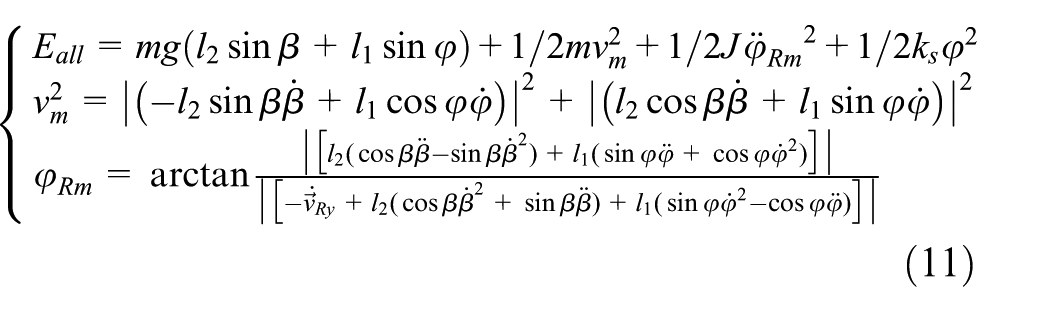
The overall lateral energy of the car becomes

Theory verification
Real vehicle test
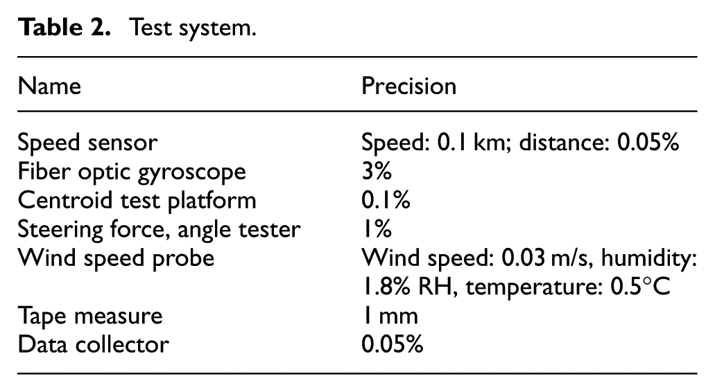
In order to verify the actual effectiveness of the proposed energy model, we apply this model to the experiment, specifically including the double-shift experiment of 60 km/h, as shown in Figure 10, and the parameters of test system, as shown in Table 2. Due to the great danger of the rollover, the speed of the vehicle is low and the steering speed is also small, there is no rollover, and the parameters of the vehicle are shown in Table 3.

Real vehicle test.
Test system.
Test vehicle parameters.

As shown in Figure 11, the controlled vehicle was driven at the speed of 60 km/h, and the double-shift test was performed to measure the speed, steering angle, and roll angle. As the existence of steering angle, the longitudinal driving speed changed from 57 to 63 km/h.
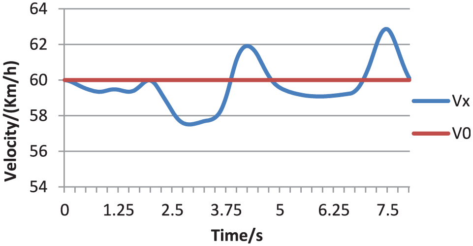
Driving speed and setting speed.
As shown in Figure 12, the left front wheel turns to a little shift at the 0.74th s, reaching −8°; then turns in reverse from 0° to 50° for 0.98 s; then turns to the other direction from 50° to −32°; and then turns from −32° to 50°.

Front wheel steering angle.
From Figures 12 and 13, it can be seen that the steering angle has reached the maximum value, but the maximum angle of tire roll angle is only ±3° and no rollover occurs. We also find that the change of roll angle is consistent with the change of steering angle, which shows that the root cause of rollover is from the steering angle at high speed.
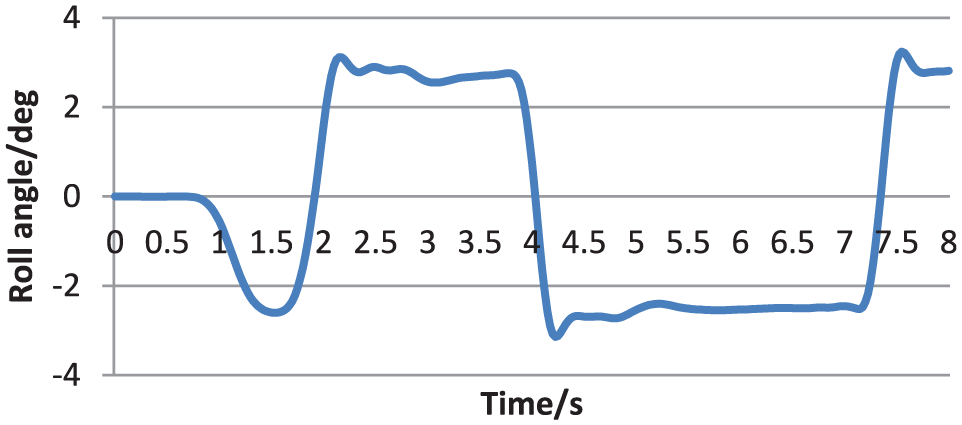
Tire roll angle over time.
According to the lateral energy method, the double-shift experiment at 60 km/h was analyzed in Figure 14. The vehicle steering at the 0.74th second resulted in an increase in the lateral speed, the roll angle, and the lateral energy which increases to 56% of the liftoff energy. In the 2.0th second, the vehicle steering from 0° to 50° caused the lateral energy to drop to 0, then increases to 62% of the liftoff energy, that is, about 2 s, the lateral energy changed between 40% and 62% of the liftoff energy. In the 4.0th second, the vehicle steering caused the lateral energy to rapidly decrease to 0, then increased to 60% of the liftoff energy, that is, about 3.2 s, the lateral energy varied between 60% and 48% of the liftoff energy. In the 7.2th second, the vehicle turned to the reverse direction, which caused the lateral energy to decrease to 0, then increases to 60% of the liftoff energy. In general, the sharp steering of the vehicle during driving causes an increase in the lateral speed, and roll angle of vehicle and tire. When the lateral energy increases to the liftoff threshold, liftoff occurs, and continues to increase to the rollover threshold and rollover will occur.
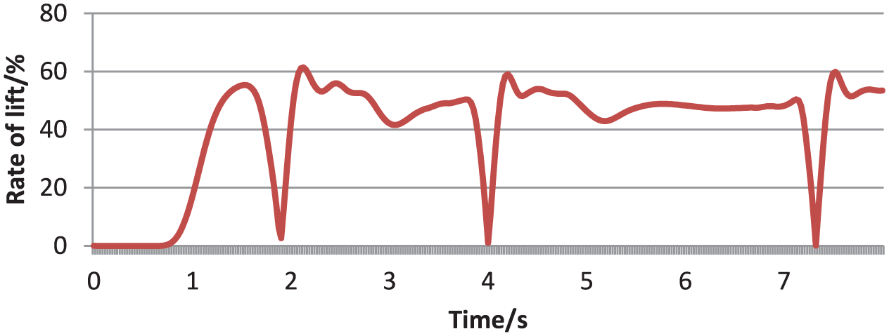
Roll rate based on the lateral energy method.
Simulation experiment verification
In order to further verify the validity of the proposed energy method, in Carsim, the Fishhook experiment (40, 50, and 60 km/h) has been conducted, and the friction coefficient of the road surface is 0.85. Vehicle speed and steering angle are large to reach the degree of liftoff and rollover, and test vehicle parameters are shown in Table 4.
Test vehicle parameters in Carsim.

The changes of steering angle are shown in Figure 15. In the 1.1th second, the vehicle turned leftwards to 15.3°; in the 1.6th second, the vehicle suddenly turned to the right and the steering angle changed from +15.3° to −12.4°. No rollover occurred in the conditions of V = 50 km/h and V = 40km/h; however, in the 3.0th second with V = 60km/h, rollover occurred.

Steering angle.
The changes of driving speed under three conditions are shown in Figure 16.

Speeds under three conditions.
Figure 17 is a roll estimation algorithm based on the LTR (load translation rate). In these three cases, only when V = 60 km/h, liftoff occurred in the 1.6th and 2.4th second with LTR = 100%; however, rollover cannot be predicted, in fact, rollover occurred in the 3.15th second. Because the LTR theory is based on the vertical load transfer rate of two left wheels and two right wheels, rollover case cannot be predicted.

Liftoff prediction with LTR.
According to the lateral energy theory prediction: in Figure 18, V = 60 km/h, it is predicted that the vehicle has enough liftoff energy in the 1.9th second and the vehicle lifted off the ground in the 2.1th second, that is, the proposed prediction is 0.2 s ahead of the actual situation; it is predicted that the vehicle has enough rollover energy in the 2.7th second and the vehicle rolled over in the 3.15th second, that is, the proposed prediction is 0.45 s ahead of the actual situation; under the conditions V = 50 km/h and V = 40 km/h, it is predicted that the vehicle will not rollover, which is consistent with the actual case.
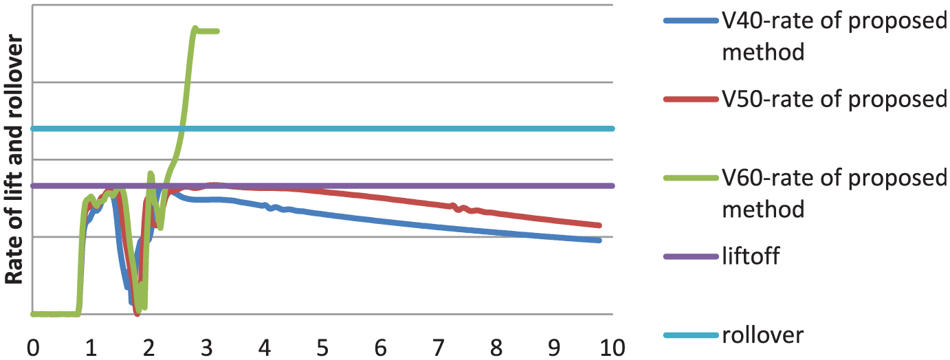
Lateral energy prediction method.
If the lateral energy model does not include the effect of tire lateral deformation, the theoretical prediction of liftoff time will be delayed by 15% and the theoretical prediction of rollover time will be delayed by 22%; the changes in the tire lateral deflection angle and wheelbase are shown in Figures 19 and 20, respectively; and Table 5 shows the comparison between LTR and lateral energy method for estimating the rollover.

Tire lateral deflection angle with V = 60 km/h.

Wheelbase B changes with V = 60 km/h.
Comparative analysis between LTR and lateral energy method.

From the experiments of the real vehicle and simulation vehicle under different maneuvers, we have applied the proposed rollover prediction algorithm to several different conditions, which range from non-liftoff, non-rollover, to liftoff or rollover. The improved rollover prediction algorithm experiment provides a consequence which predicts every case of liftoff and rollover. With the existing LTR model, we can find that only liftoff can be predicted, but not rollover, whereas the proposed rollover prediction algorithm can give the prediction of pre-liftoff and pre-rollover, significantly increasing the effectiveness of active prevention countermeasures.
For the Fishhook case at V = 40 km/h and V = 50 km/h with μ = 0.85, even though we find that the vehicle does not lift off, shown in Figure 20, the individual wheel loads show that the rear inside wheel does lift off momentarily; however, the proposed rollover prediction algorithm does not predict the liftoff, since our algorithm predicts liftoff and rollover of an entire side, at least two wheels, not a single wheel.
With the LTR method, we cannot predict the liftoff until liftoff has occurred, also cannot predict rollover, whereas the proposed rollover prediction method has the ability to predict liftoff and rollover in advance, which significantly increases the effectiveness of vehicle active safety.
Conclusion
Based on the energy method, the rollover theory of the vehicle is developed from nonlinear vehicle system dynamic. The effect of the suspension and the tire on liftoff and rollover is taken into account, and the double-line test and Fishhook test are used to verify the proposed model. Each test of the different vehicles applies the predictive algorithm to different cases (liftoff, rollover, and no liftoff or no rollover), and especially in the test case of V = 60km/h, it is predicted that the vehicle has enough liftoff energy in the 1.9th second and the vehicle lifted off the ground in the 2.1th second, that is, the proposed prediction is 0.2 s ahead of the actual situation; it is predicted that the vehicle has enough rollover energy in the 2.7th second and the vehicle rolled over in the 3.15th second, that is, the proposed prediction is 0.45 s ahead of the actual situation. The rollover predictive method can be proved to be effective and conservative.
Footnotes
Handling Editor: Marianna Imprialou
Declaration of conflicting interests
The author(s) declared no potential conflicts of interest with respect to the research, authorship, and/or publication of this article.
Funding
The author(s) disclosed receipt of the following financial support for the research, authorship, and/or publication of this article: This project was supported by the National Natural Science Foundation of China (grant no. 51705220), the Jiangsu Province Higher Education Natural Science Research Project (grant no. 17KJD580001), the Jiangsu Provincial Higher Education Natural Science Research Major Project (grant no. 17KJA580003), and Foundation for Jiangsu Province “333 Project” Training Funded Project (grant no. BRA2015365).