
Abstract
A load-sharing analysis methodology was proposed for the multiple-branch star gear transmission which is composed of a number of closed-loop power flows. The moment equilibrium and deformation compatibility equations for the two-stage star gearing were derived, which are clearly different from that used in planetary gear transmission. Then the load-sharing analysis model was established and employed to systematically study the load-sharing behavior of the two-stage three-branch star gearing, some untouched aspects were investigated. Results show that the most sensitive directions of the central and star gear assembly errors on load-sharing are along the meshing line. The effects of the size and direction of the central gear–manufacturing errors on load sharing are the same for each branch, the initial directions of the central or a certain star gear–manufacturing errors will have no effect on the load-sharing coefficient of the system, but the initial directions of the assembly errors will. The conditions in which the load distribution curves repeat the first track were also obtained. Finally, a numerical example of a three-branch star gear aviation reducer was adopted to verify the feasibility of this proposed method, and the calculation results show good agreement with a previously published and validated model.
Introduction
It is well accepted that a multiple-branch gear transmission can reduce the load of each path significantly by splitting the input power into a number of parallel paths, while improving the power density ratio of the system and making the structure more compact. A star gear train, which is a type of fixed-axis multiple-branch gear transmission, has clear advantages in terms of intensity, rigidity, and working reliability compared with a planetary transmission, which has granted it wide application in aviation and automotive industries.
These advantages of multiple-branch gear transmissions, however, can only be achieved if the load is evenly distributed among all of the paths. This ideal load sharing is not easy to obtain owing to manufacturing and assembly errors. To solve this problem, extensive research has been carried out. Hayashi et al., 1 Ma and Botman, 2 and Hidaka and Sugimoto 3 focused on the load sharing of planetary gearing and discussed the influence of gear errors and misalignments on the load distribution. Yanabe et al. 4 studied the effects of positional deviation and bearing stiffness on the load sharing in star gearing. Sikorsky 5 proposed a power-split gear transmission with two branches and applied it to the main reducer of a Comanche helicopter. Krantz and Delgado6,7 subsequently carried out experiments at NASA analyzing the static load-sharing behavior. Yoshino et al. 8 probed into the self-centering characteristics of floating sun gears used in star gearing. Kahraman and colleagues9–12 systematically studied the characteristics of load sharing of planetary gearing both experimentally and through simulations. Singh and colleagues13–18 proposed an analysis model and a physical explanation of the load-sharing behavior of planetary gears. Qiu et al. 19 investigated the load-sharing characteristics of a planetary gear in large wind turbines by considering the effects of gravity. Iglesias et al. 20 conducted a systematic study on the effects of planet positioning errors on the load sharing of a planetary transmission. Fang et al. 21 analyzed the dynamic behavior of a star gear system with three branches. Bao and Zhu 22 studied the static load-sharing characteristics of two-stage star gearing and calculated the offsets of the basic components. Yuan et al. 23 discussed the relationship between static load sharing and the manufacturing and assembly errors of the basic components.
The load-sharing analysis methods applied in above studies, however, only considered the mechanical equilibrium relationship between adjacent components, and little research has been conducted on the load-sharing behavior of multiple-branch gear transmissions when considering a system composed of a number of closed-loop power flows.24–26 A deformation compatibility condition occurs among all gears in the same closed-loop power path, as determined by the authors, and presented and validated in previous studies.24,25 To reveal the essential feature of a multiple-branch power-split gear transmission, this characteristic should not be ignored. But these studies did not distinguish the differences between star and planetary transmissions with regard to the deformation compatibility equations, which is less rigorous because in planetary gearing, the planet gear meshes with both the sun and internal gears, but in the two-stage star gearing, the sun gear meshes with the star gear at the first stage, and the internal gear meshes with the star gear at the second stage. Only when the tooth numbers of the two star gears in the same axis are equal and the torsion and bending deformations of the axis are neglected, the process of derivation in planetary gearing can be adopted to two-stage star gearing.
Herein, a new method is created for a load-sharing analysis of three-branch star gearing using the deformation compatibility, and a strict derivation and verification, are described. Some untouched aspects of the load-sharing behavior of star gearing are also elucidated, such as the relationship between the load-sharing coefficients of different stages within the same branch, and the most sensitive directions of the central gear assembly errors on the load sharing. The most sensitive directions of the star gear assembly errors on the load sharing are also detailed. The condition in which the load distribution curves repeat the first track is also described. Finally, some concluding remarks regarding this research are provided.
Moment equilibrium and deformation compatibility equations
Two-stage three-branch star gearing
As shown in Figure 1, a three-branch star gear train consists of two central gears (a sun gear and an internal gear) and three dual star gears. Input power flow is transferred to the sun gear and split into three paths by the first stage of dual star gears

The two-stage three-branch star gear transmission: (a) three-dimensional model and (b) kinematic diagram.
To ensure a uniform distribution of the input torque and eliminate the need for additional load-sharing mechanisms, floating central gears are widely applied in engineering to enable the whole transmission system to be compact and highly reliable. Considering that the coupling spindles are relatively stubby and that star gears are normally not used as floating components, both the torsional and bend deformation of coupling spindles between the first and second star gears, and the bearing elasticity for dual star gears, are ignored in this study.
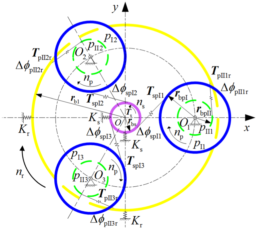
Moment equilibrium equations of the system
A mechanical model for a three-branch star gear train is shown in Figure 2. The teeth are treated as elastomers, and torsional and contact deformations occur under a load. Elastic support is adopted on the central gears. Here, the subscripts s and r represent the sun gear and the internal gear, respectively. Ts represents the input torque, s represents the sun gear, Tij indicates the torque applied to gear i from gear j. The torque between each gear is TspIi, TpIIir, and TpIis, TrpIIi, where pIi is the ith star gear at stage I and pIIi is the ith star gear at stage II. Such as, TspIi represents the torque applied to the sun gear from the ith star gear at the first stage(pIi). The drive torque is assumed to be positive, and the load torque is considered to be negative.
Mechanical model for three-branch star gear train.
The following equation set can be obtained according to the moment equilibrium conditions of the sun and dual star gears, as further shown in Figure 2

According to the force and reaction force balance conditions, the following equation is obtained

Here,

Deformation compatibility equations of the system
As shown in Figure 2, the meshing angle equations of each gear pair are as follows

where

It is important to note that
The transmission error of the kth branch can be converted into the equivalent angular displacement relative to the sun gear

Then substituting equations (4) and (5) into equation (6)
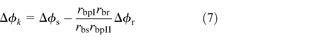
We can see that equation (7) is clearly different from that derived for the planetary transmission.24,26 According to equation (7), the following equation can be obtained

Based on the above analysis, choosing

Load-sharing analysis model
Angular transmission error caused by deformation
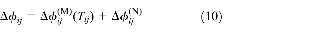
The meshing transmission error of gear pair ij consists of two parts, as shown in equation (10)
where

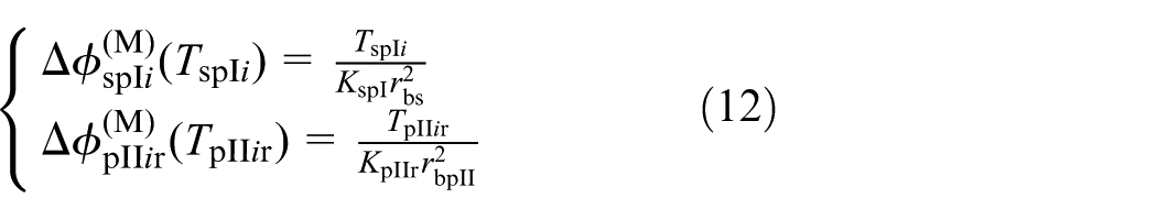
where
Angular transmission error caused by errors and floating
If the manufacturing and assembly errors, as well as the floating of basic components, can be neglected,
Angular displacements caused by manufacturing and assembly errors
Figure 3 shows the manufacturing and assembly errors mentioned in this research, and the errors of the dual star gears including the first and second stages. Here, the manufacturing errors mainly refers to the manufacturing eccentricity and the pitch error caused by the process of gear machining, while the assembly errors mainly refers to the assembly eccentricity of the central and dual star gears.
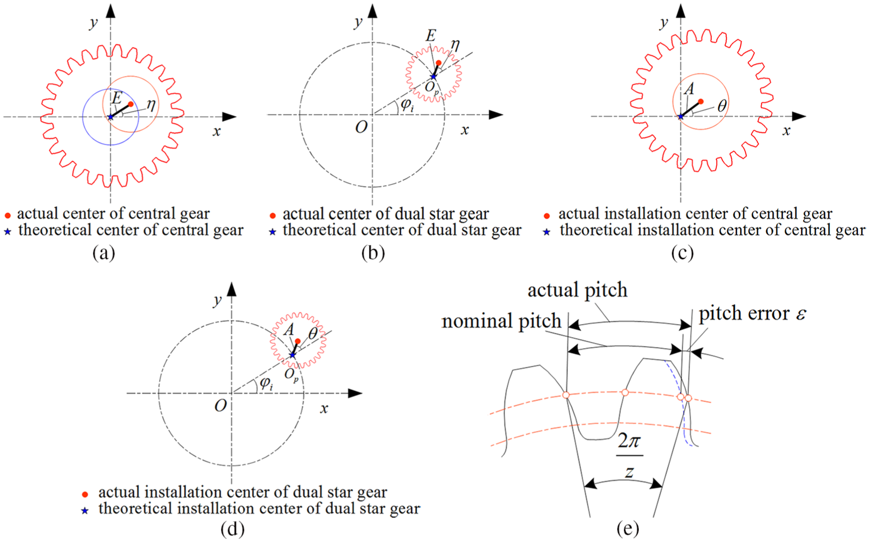
Manufacturing and assembly errors of the gear: (a) manufacturing error of central gear, (b) manufacturing error of dual star gear, (c) assembly error of central gear, (d) assembly error of dual star gear, and (e) pitch error.
All angular displacements caused by the manufacturing and assembly errors are as follows

where the subscripts
The accumulated angular displacements of each gear pair can then be calculated using equation (14)
Angular displacements caused by floating of basic components
The angular displacements caused by floating of basic components are as follows
where
Thus, the entire angular displacements caused by such errors and floating can be calculated using equation (16)

By substituting equations (11) and (16) into equation (10), the angular transmission errors can be obtained as follows
Bearing stiffness and floating of central gears
The bearing stiffness and floating of the sun gear and the internal gear are as follows

where
Load-sharing coefficient of the system
The simultaneous solutions to equations (3), (9), (17), and (18) are


where,

Therefore

The load-sharing coefficient of the system is then defined as G and can be calculated using equation (23) as

Numerical examples and discussions
The load distribution of a two-stage three-branch star gear reducer used in aviation is calculated based on the above analysis. The basic parameters of the gears in this reducer are shown in Table 1.
23
The input power is 1250 kW at a rotating speed of 20,000 r/min. The equivalent meshing stiffness of the first and second stages is
Basic parameters of the gears.
Effects of manufacturing and assembly errors on load sharing
Sensitivity analysis of the errors
Assuming that all errors are

Load sharing of the system when an error occurs alone: (a) Es occurs alone, (b) As occurs alone. (c) EpI1 occurs alone, (d) ApI1 occurs alone, (e) EpII1 occurs alone, (f) ApII1 occurs alone, (g) Er occurs alone and (h) Ar occurs alone.
Figure 4(a) shows that the load distribution curve of each branch changes periodically with only a phase difference between them when a manufacturing error of the sun gear occurs alone, whereas it remains unchanged when an assembly error occurs independently, as shown in Figure 4(b). This is because the angle of the manufacturing error on a central gear changes with the rotation of the corresponding gear, but the angle of an assembly error remains the same regardless of whether the corresponding gear is rotating. Similar conclusions can be obtained for an internal gear, as shown in Figure 4(g) and (h).
For the star gears, shown in Figures 4(c)–(f), the load distribution curves of all branches change periodically when each manufacturing error of a star gear occurs independently, whereas they remain unchanged when an assembly error of one of the star gears occurs. In contrast to the central gears, phase and amplitude differences occur between branch curves with and without manufacturing errors. The fluctuation amplitude of the curve for an error-existing branch is relatively large, whereas the two curves for error-free branches are synchronous. In addition, the curve amplitude of an error-existing branch is smaller than that of error-free branches when an assembly error occurs on the first stage, whereas the result is just the reverse when an assembly error occurs on the second stage, this is because the equivalent meshing error between a sun gear and star gear I increases as a result of this particular assembly error, whereas the equivalent meshing error between star gear II and an internal gear decreases.
From Figure 4, we can also see that the load distribution of the system is most sensitive to errors (including manufacturing and assembly errors) of the internal gear, followed by errors in star gear II and a sun gear successively, with the errors of star gear I being the least sensitive factor. Therefore, the wisest choice is to improve the manufacturing and assembly precision of the internal gear or adopt a floating mechanism to an internal gear to make the load sharing equal. In addition, the load distribution curve does not repeat the first track in the second lap of the internal gear (as shown in Figure 4(c) and (e)) because the ratio of the number of teeth of inner meshing gears is not an integer. Theoretically, the load distribution curve will be coincident with the previous track when the number of rotating teeth reaches the least common multiple of the number of teeth of the inner meshing gears.
Figure 5 shows the effects of the assembly errors on the load sharing of the system. As can be seen in Figure 5, the load-sharing coefficient of the system will increase as the size of the error increases. For the central gears, there are three sensitive zones, these areas are around the assembly angles of the star dual gears for a sun gear, whereas for an internal gear, they are around the position angles which are the middle position of two adjacent star dual gears. This is because a preloading of the star gear will occur when the central gears are close to it, and this excess in transmitted torque is relatively large when it occurs on a single star gear as compared to two star gears. For the star dual gears, there are only two sensitive zones, which are around the tangential direction, as reported in previous studies. Further details of these angles are given in the following section.

Effects of assembly errors on the load sharing of the system.
Effects of error direction
Error direction of central gears
The manufacturing errors of central gears have the same effect on each branch, namely, the amplitude of the load-sharing curve and the load-sharing coefficient of the system remain the same; however, the phase will change as the initial error direction changes, as shown in Figure 6. The size of all errors is

Load sharing with different manufacturing error directions of the central gears: (a)
The assembly error direction of the central gears will not change with the rotation, and therefore different directions will lead to different load distributions, as shown in Figure 7.

Load distribution with different assembly error directions of the central gears: (a)
Figure 8 shows that the assembly error angles of the central gears, that is, around

Load-sharing coefficient of the system with different assembly error directions of the central gears: (a) sun gear and (b) internal gear.
Error direction of star gears
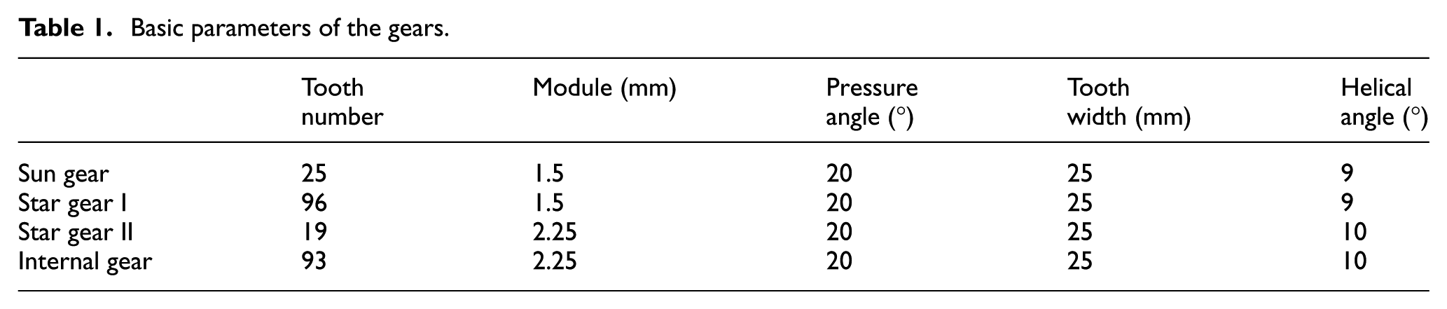
The effects of the star gear–manufacturing error directions on the load sharing are shown in Figure 9. Here, the load will be evenly distributed only if the initial error directions of the three branches are the same, and the load-sharing curve of each branch will have a periodical change in any other case. The angular coordinates in Figure 9 represent the angles of the manufacturing errors.
Load sharing with different manufacturing error directions of star gears: (a)
Figure 10 shows that the load will be evenly distributed when the assembly error angles of all branches are equal to each other, which is consistent with the conclusion previously published. 13

Load distribution with different assembly error directions of star gears: (a)
Figure 11 shows clearly that the load-sharing coefficient of the system is most sensitive to assembly error angles of
Load-sharing coefficient of the system with different assembly error directions of the star gears: (a) dual star gear I and (b) dual star gear II.

The most sensitive direction of the star gear assembly error.
It should be noted that the initial manufacturing error direction of a certain star gear has no effect on the load-sharing coefficient of the system with the exception of the phase of the load-sharing curve, which is the same as with the central gears.
Effects of basic component floating on load sharing
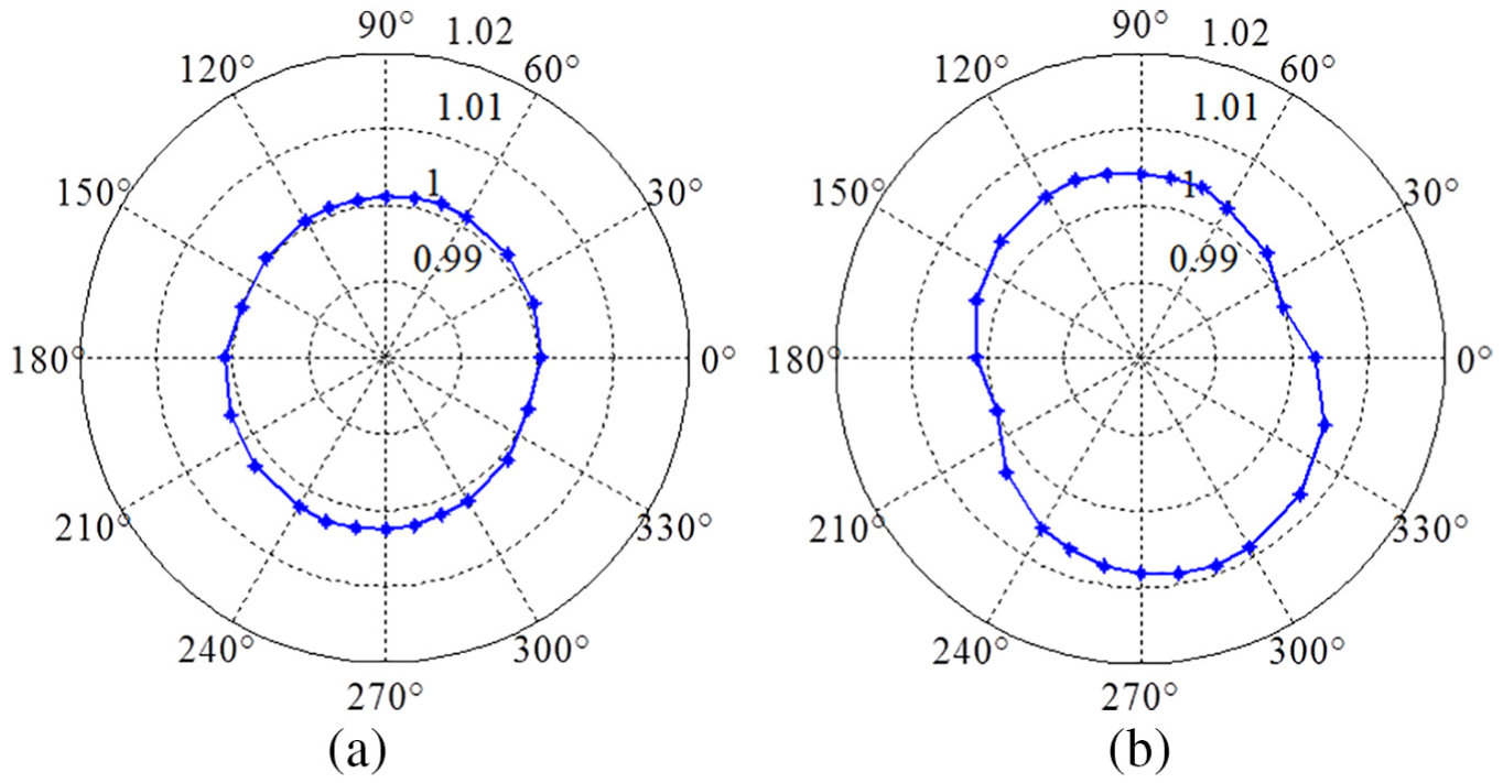
Figure 13 shows the effects of the central gear floating on the load sharing of the system, which is calculated under all of the manufacturing and assembly errors discussed above (shown in Tables 2 and 3). The results of the load-sharing coefficient of the system under different floating cases are shown in Table 4. As can be seen in Figure 14, the floating of the central gears is conducive to a uniform load distribution for this system. In addition, the floating of an internal gear is superior to that of a sun gear, and better results will be achieved if all of the central gears are floating.
Effects of floating on the load sharing of the system: (a) no floating gears, (b) all floating gears, (c) floating sun gear, and (d) floating internal gear.
Errors in stage I.

Errors in stage II.

Load-sharing coefficient of the system under different case of floating.

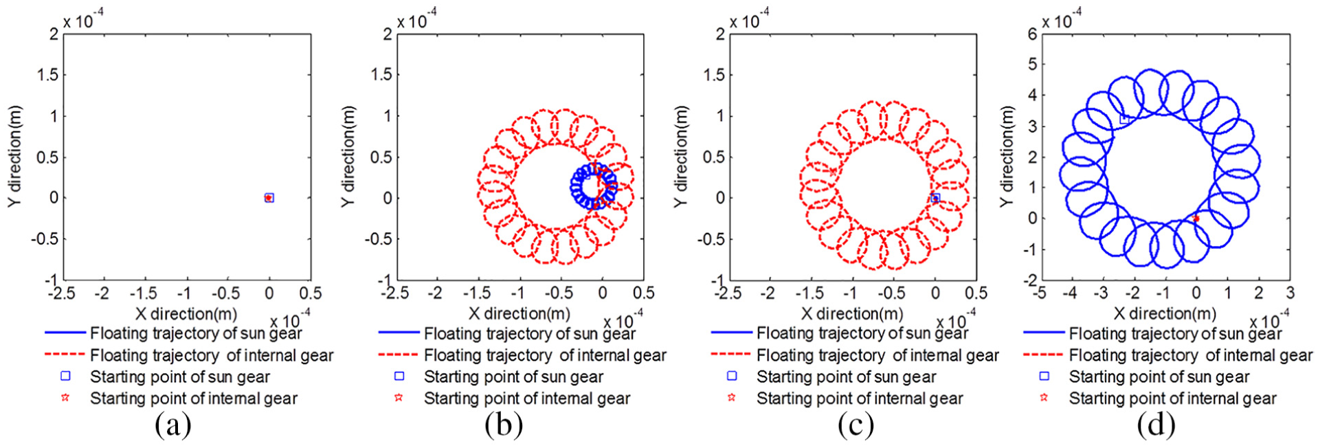
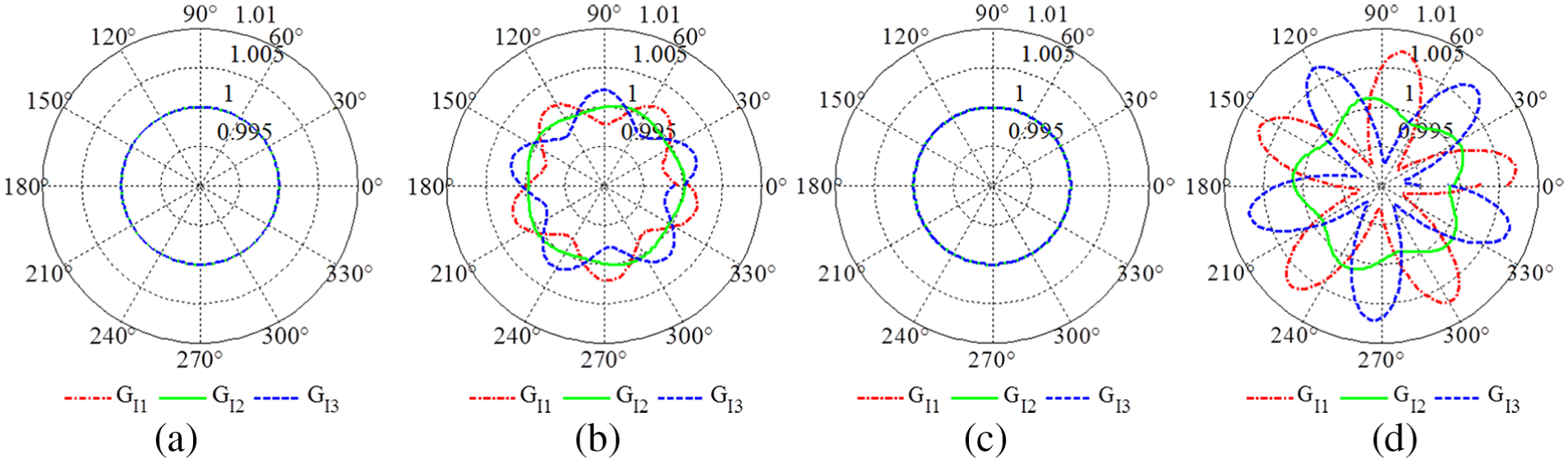
Floating trajectories of the central gears: (a) no floating gears, (b) all floating gears, (c) floating internal gear, and (d) floating sun gear.
The floating trajectories of the central gears corresponding to the above working conditions are shown in Figure 14.
Effects of basic component bearing stiffness on the load sharing
The influence of the central gear–bearing stiffness on the load sharing of the system under all of the above errors is shown in Figure 15, which takes the ratio of bearing stiffness to

Effects of bearing stiffness on the load sharing of the system.
As can be seen from Figure 15, the load will be evenly distributed if the bearing stiffness of the movable components is below 0.01
Feasibility analysis
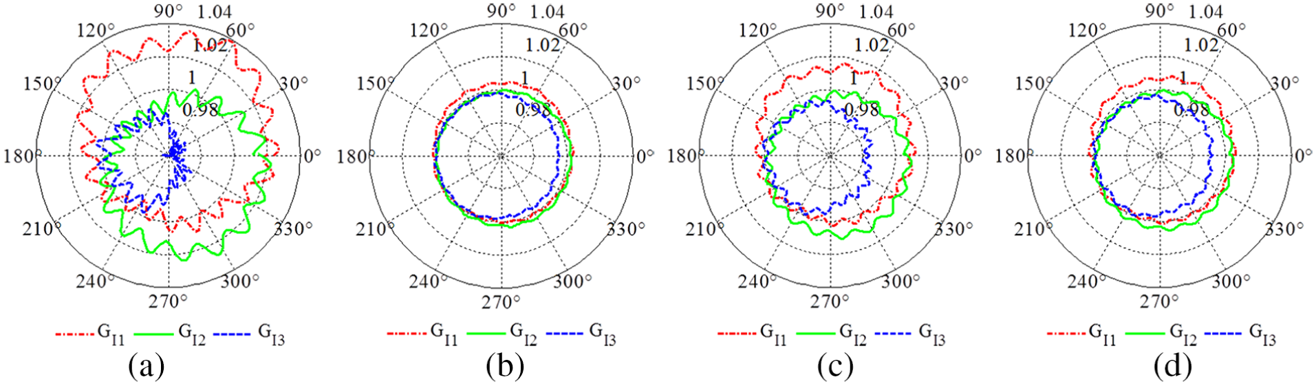
The feasibility of this method was demonstrated using above numerical example of a three-branch star gear aviation reducer. Here, the load sharing of the system under the same error condition (shown in Tables 5 and 6) is shown in Figure 16, where the load-sharing coefficient of the system is 1.011, which is 1.012 in the previously validated model, 23 the error is less than 0.1%.
Errors in stage I.

Errors in stage II.

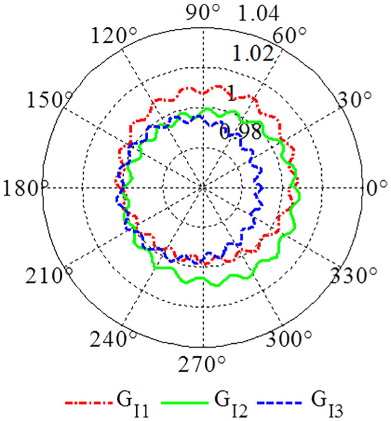
Load sharing of the system under the same error conditions in a previous work.
Comparing Figures 13(a) and 16, the load-sharing coefficient of the system is relatively large in the former case, and the shapes of the load-sharing curves are different, although the error sizes are the same, which is due to the irregular distribution of the manufacturing and assembly errors along the circular direction.
Conclusion
This load-sharing analysis model considers the effects of almost all gear-manufacturing and assembly errors, as well as the floating and bearing stiffness of the central gears on the load sharing, particularly the directional sensitivity of the position errors of the central and star gears.
It was shown that an eccentric error of an internal gear is the most sensitive to the load sharing of the system. Three sensitive zones of the central gear position errors, and two sensitive zones of the star gears on the load sharing were obtained, and the most sensitive direction of the star gear assembly error is in the direction of the meshing line, around the tangential pinhole positions, as reported in previous studies. The effects of the size and direction of the central gear–manufacturing errors on the load sharing are the same for each branch, with the exception of a phase difference. The initial directions of the manufacturing errors of the central gears or a certain star gear will have no effect on the load-sharing coefficient of the system, but the initial directions of the assembly errors will. The load distribution curve will be coincident with the previous track when the number of rotating teeth reaches the least common multiple of the number of teeth of the inner meshing gears.
Floating of the central gears, particularly an internal gear, results in significant improvement for a uniform distribution of load in the star gearing, and better results will be obtained if all of the central gears float together. In addition, a uniform distribution of the load sharing will be obtained if the bearing stiffness of the central gears is sufficiently small.
The moment equilibrium and the deformation compatibility equations derived for the planetary gear transmission cannot be adopted directly to the two-stage star gearing due to the different meshing relationships.
Footnotes
Handling Editor: Jose Ramon Serrano
Declaration of conflicting interests
The author(s) declared no potential conflicts of interest with respect to the research, authorship, and/or publication of this article.
Funding
The author(s) disclosed receipt of the following financial support for the research, authorship, and/or publication of this article: The authors gratefully acknowledge the financial aid and support from the National Natural Science Foundation of China (grant no.: 51705419 and 61701397), the Natural Science Foundation of Shaanxi Province of China (grant no.: 2017JQ5048), and the China Postdoctoral Science Foundation (grant no.: 2018M633540).