
Abstract
A load sharing analysis methodology is proposed for a new type of power split spiral bevel gearing system based on the closed-loop characteristic of the power flow. First, the mechanical structure model and the moment equilibrium equations of the system are constructed, and then the deformation compatibility equations describing the relationship between the moment and the normal deformation of tooth surface are derived. Second, an accurate model for load sharing calculation of a one-input-two-output working condition is proposed, and a general formula for the simplified engineering load distribution calculation is derived. Finally, an experiment is designed to demonstrate the feasibility of this method. It is found that the measured tooth root strain ratio of the 1–2 and the 1–4 branches coincides with the theoretical analysis results. The proposed analysis and experimental method provides a new approach for analyzing the load distribution of the power split gear transmission with a closed-loop power flow.
Introduction
Power split gearing systems such as planetary, star, parallel shaft, and other forms of gear transmissions are widely used in the engines and reducers in aviation, marine, and automobile industries. The rationale of the power split technology is that the input torque to be transferred is split up into
These advantages of power split gear transmissions, however, can only be achieved if the load is evenly distributed among all of the branches. A significant volume of studies have been carried out to explore the load sharing characteristics of these power split gearing systems. Hidaka and collegues1–3 investigated the unequal load sharing of planetary gear transmissions caused by manufacturing and installation errors. The experimental results showed that the floating central members and their deformations could help improve load sharing among the planet gears. Ma and Botman 4 studied the effects of gear errors, misalignments and gear support conditions on planetary transmission. Hayashi et al. 5 studied the effects of transmitted torque on load sharing characteristics of a three-planet system. Kahraman6,7 used a simplified discrete model to investigate the planet load sharing characteristics of a four-planet system and the ring gear flexibilities were considered in their later work. 8 Krantz 9 and Krantz and Delgado 10 performed an experimental study to analyze the load sharing characteristics of the split-path transmission. Bodas and Kahraman 11 classified the manufacturing errors of planetary gear sets that influenced the load sharing characteristics in three distinct groups, and these different types of errors were combined in a total planet error. Singh12,13 analyzed the sensitivity of pinhole position errors and the number of planets to load sharing behavior, and proposed that the unequal load sharing of epicyclic gears has major implications on transmission torque capacity, system sizing, and tolerancing schemes. Singh et al. 14 also studied the influence of certain key factors in planetary transmissions on gear stresses and planetary load sharing. Bao and Zhu 15 analyzed the dynamic load sharing characteristics of a two-stage planet gear train with consideration for the manufacturing and assembly errors. Ligata et al. 16 described the impact of certain types of manufacturing errors on gear stresses and the load sharing of an n-planet (n = 3–6) planetary gear set by an experimental study. Ligata et al. 17 also presented a simplified discrete model to predict the load sharing characteristics of a planetary gear set having carrier planet position errors, and a set of closed-form load sharing formulas were obtained which allow the calculation of load sharing as a function of position errors associated with each planet. Qiu et al. 18 investigated the load sharing characteristics of the spur planetary gear in wind turbines and the influence of gravity, bedplate tilt angle, and ring support stiffness on load sharing was examined. Du et al., 19 Dong et al., 20 and Shuai et al. 21 studied, respectively, the load sharing of the 2K-H-type planetary gears, the two-branch power split, and two-stage star gearing systems based on the characteristic that the system composed a closed-loop power flow, the deformation compatibility, and moment equilibrium equations of these systems were used to calculate the load sharing coefficients.
While the structures of the traditional planetary and star gear trains are complicated and the direction of the power flow is single, Gu et al. 22 designed a new type of power split spiral bevel gearing system. This system is composed of four symmetrically arranged spiral bevel gears and all of their shaft angles are 90°. With simple and compact framework, this system can input and output multiple branch powers in parallel or crossing forms, such as one input with two or three outputs, two inputs with one or two outputs, and so on. This system has shown good prospects for use in military and civilian fields.
The objective of this investigation is to systematically analyze the load sharing characteristics of a special form of this power split spiral bevel gearing system—one input with two outputs—which can be used in helicopter and vessel drives. First, a mechanical structure model for the system is established according to the closed-loop characteristic of the power flow. Then, the moment equilibrium equations as well as the deformation compatibility equations describing the relationship between the torque and the normal deformation of the tooth surface are derived. Based on these equations, the theoretical load sharing calculation models—an accurate calculation model and a simplified engineering calculation model—are proposed, and a load distribution formula that directly reflects the load sharing situation of the system is derived. Finally, the feasibility of the theoretical model is clearly illustrated by an experiment and some conclusions are given.
Mechanical structure model of the system
The internal structure diagram and the three-dimensional (3D) model of this gearing system are shown in Figure 1. The gear ratio is 1:1 and the shaft angle is 90°, all the gears are supported by rolling bearings at the ends of the shafts and all of the four centerlines are in the same horizontal plane. This research focuses on a special form of the system that is intended for application in a helicopter (Figure 2) or a vessel (Figure 3) drive. As shown in Figure 2, the input power is split up into two branches, which will be output through the main reducer to the main rotor and through the tail reducer to the tail rotor, this form of a two-branch power split meets the requirements for helicopter motion and power transmission. As shown in Figure 3, the working conditions of one engine driving one propeller is that clutch 6 is open when hydraulic couplers #3 and #4 are closed, and the main engines #1 and #2 are running simultaneously. The working conditions of one engine driving two propellers is that clutch 6 is closed when main engine #1 is running separately with hydraulic coupler #3 being open, or the main engine #2 running separately with hydraulic coupler #4 being open.

Power split spiral bevel gearing system: (a) diagram and (b) 3D model.

The system when applied in a helicopter drive.

The system when applied in a vessel drive.
The mechanical structure model of this two-branch power split spiral bevel gearing system is shown in Figure 4.

Mechanical model of the system.
Since there are only two branches of output, the following equations can be obtained according to the moment equilibrium condition of the system

The support stiffness of these gears is relatively large, and thus their bearing elasticity is ignored in this study, and the following moment equilibrium equations can be obtained according to the moment equilibrium condition of the gears

where
An equation set containing three independent equations can then be obtained from equations (1) and (2)

Deformation compatibility of the system
The relationship between rotation angles of the gear pairs in this power split system is shown in Figure 5.

Rotation angles of the gears.
These angles satisfy equation set (4)

where
The deformation compatibility equation of the system is then obtained from equation set (4)

where the angular deformation

where
Load sharing analysis
Accurate calculation model
The range of the load torque for each gear pair is from 0 to
There are eight corresponding meshing positions for each of the four gear pairs in every meshing period, while the equations that represent the relationship between the deformation angle and the ever-changing load torque can be obtained by fitting for each of the eight meshing positions, 32 curves are fitted, and their corresponding functions can also be obtained. 27 If the load torque is known, the meshing stiffness curve can then be obtained. Figure 6 shows the relationship between the deformation angle and the ever-changing load torque for the eight meshing positions of the gear pair 1–2. As can be seen from Figure 6, the relationship is not linear, but it tends toward linearity as the load torque increases. Figure 7 shows the meshing stiffness curve of the gear pair 1–2 under a known load torque of 500 N m. As can be seen, the meshing stiffness varies with time, and the period is the meshing period.

Deformation angles under different load torques.

Meshing stiffness curve under 500 N m.
The load torque of each of the four gears

It is difficult to solve nonlinear equation (7) directly because the initial value is not easy to determine. Thus, an optimization model is created to solve for the load torque
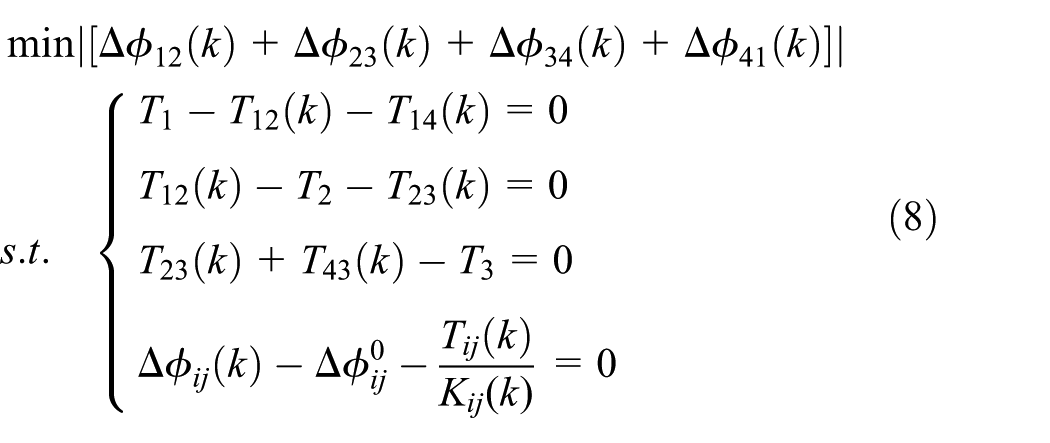
The elimination method is used here for the constraint equations.
One thing to note is that the variable k represents only the sequence number of the gear pair meshing positions from mesh-in to mesh-out. The kth meshing positions of the four gear pairs are not necessarily the same, due to manufacturing and assembly errors. These errors will influence the load sharing of the system by changing the values of
Engineering calculation model
The instantaneous load sharing of the system at each meshing position can be obtained using an accurate calculation method. However, time-averaged load sharing is of greater concern for actual engineering applications. Therefore, it is necessary to make appropriate engineering simplifications and approximations of the above method. A simplified engineering calculation model is proposed in this study.

It is important to note that the relationship of the angle


The load torque
According to equations (15) and (16)

According to equations (12), (14), (17), and (18)

According to equations (11) and (19)

Substituting equation (10) into equation (20)

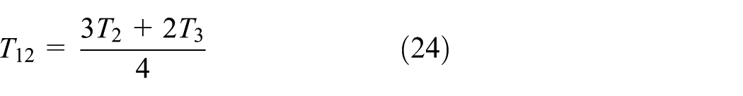
Then the following equation can be obtained
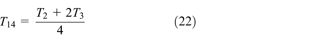
According to equations (10) and (11)

Substituting equation (23) into equation (22)
The general formula for the ratio of the torques

As can be seen from equation (25), the load sharing of the system is almost equally distributed, while the
Equation (25) is no longer valid if manufacturing and assembly errors exist. However, the equations (10)–(15) and (17) are still valid and are only needed to recalculate the parameters

Experimental verification
An experiment was designed to verify the above theoretical method. The experimental gear was made of 20CrMnTi, the Rockwell hardness was 60, and normalizing and carburization were used as the heat treatment methods. The basic parameters of the four gears are shown in Table 1. The assembly diagram of the power split spiral bevel gearbox is shown in Figure 8.
Basic parameters of the gears.
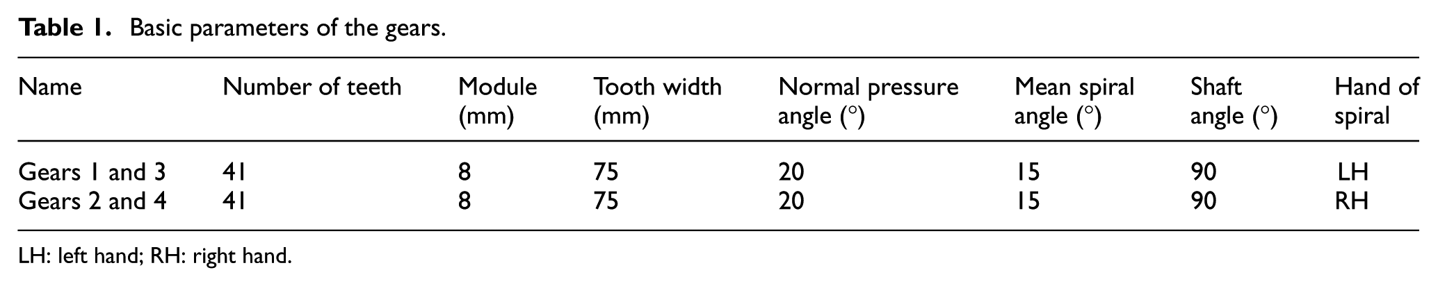
LH: left hand; RH: right hand.
Power split spiral bevel gear transmission.
The load sharing characteristic is determined by monitoring the strains on the root of several teeth in gears 1 and 2. A 32-channel signal testing and analysis system (DH-5923) was used to acquire and analyze the strain signals. The contact pattern of standard installation without errors is shown in Figure 9. The experimental system and site are shown in Figures 10 and 11, respectively.

Contact pattern: (a) convex and (b) concave.

Experimental system with one input and two outputs.
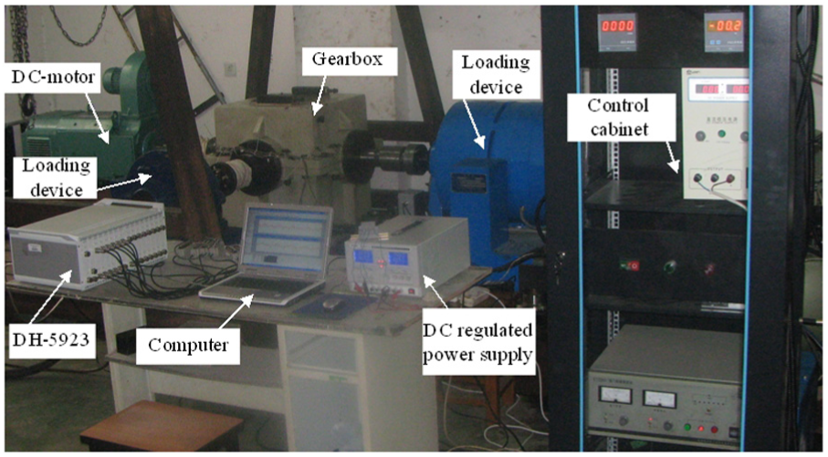
Experimental site of the power split spiral bevel gearing system.
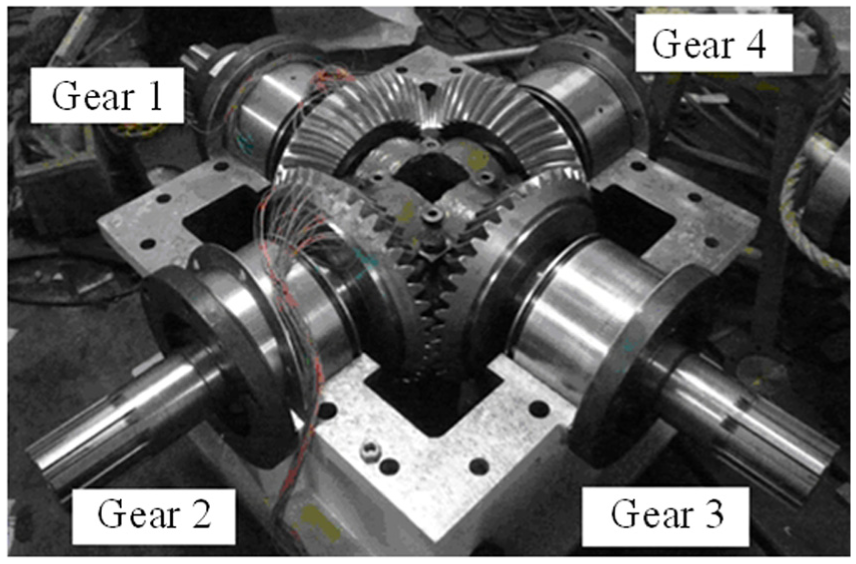
The locations of the strain gauges are shown in Figure 12. Several groups of strain gauges were mounted on the center root and the back cone root of both concave and convex sides of the selected teeth in gears 1 and 2 for accuracy in the measurement of results. The combination of the test strain gauges was chosen according to the actual conditions of the measurement.

Locations of the strain gauges: (a) center root and (b) back cone root.
The strain gauges on the concave side of the teeth in gear 1 and on the convex side of the teeth in gear 2 were chosen as the main test strain gauges in this research. The tensile stress is specified as positive and the compressive stress as negative. The strain gauge on the concave side of gear 1 outputs a positive pulse on the moment of each half-rotation because the concave side of gear 1 is the drive flank in both gear pairs 1–2 and 1–4. The pulse peak of gear 1 is the main signal for the torque split measurement.
The strain gauge on the convex side of gear 2 outputs a positive pulse when the gear pair 1–2 meshes at the strain gauge location, while it outputs a negative pulse when the gear pair 2–3 meshes at the strain gauge location, which is because the convex side of gear 2 is the drive flank in gear pair 1–2, while the concave side of gear 2 is the drive flank in gear pair 2–3.
The teeth with strain gauges in gears 1 and 2 are assembled as a meshing gear pair, and thus the pulses output from gears 1 and 2 are synchronized. The strain signal of gear 1 that corresponds to the positive pulse of gear 2 is the meshing signal of gear pair 1–2, while the signal corresponding to the negative pulse of gear 2 is the meshing signal of gear pair 1–4, that is, the sign of the pulse output from gear 2 is the judgment basis of the strain signal assignment, as shown in Figure 13 (under the known working conditions of 500 N m load on gear 3 and a rotational speed of 260 rev/min).

Strain signals of gears 1 and 2.
Taking three kinds of working conditions as examples, as shown in Table 2, the strain signals of the gears 1 and 2 after filtering are shown in Figure 14.
Working conditions.


Strains of gears 1 and 2: (a) working condition 1, (b) working condition 2, and (c) working condition 3.
According to the above analysis, when the pulse of gear 2 is positive, the corresponding pulse signal of gear 1 is the strain when gear 1 meshes with gear 2, while when the pulse of gear 2 is negative, the pulse signal of gear 1 is the strain when gear 1 meshes with gear 4. The ratio of the actual strain for gear 1 meshes with gear 2

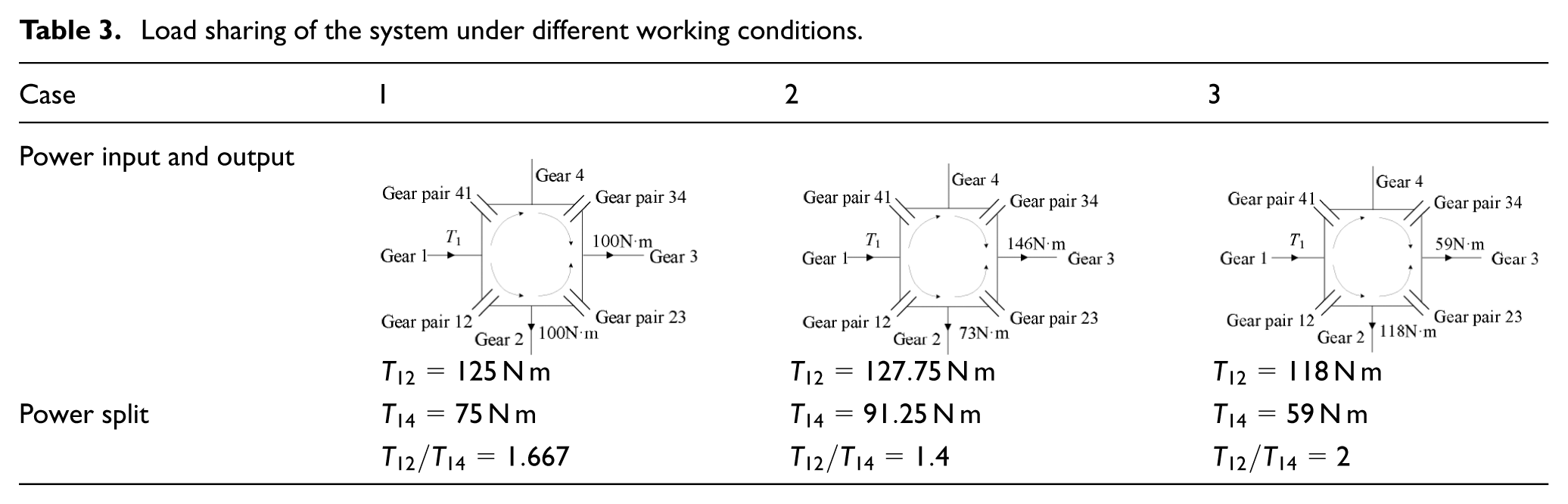
The load sharing characteristics of the system under different working conditions are shown in Tables 3 and 4. The deviation between the theoretical and experimental values of a12/a14 is calculated by the following function
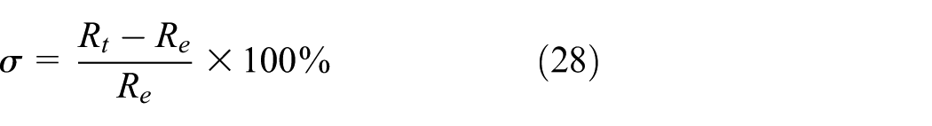
Load sharing of the system under different working conditions.
Statistical table of the experimental results.

where
As shown in Table 4, the computational results are basically consistent with the experimental results.
Conclusion
Accurate and simplified calculation models of the load sharing behavior for a new type of power split spiral bevel gearing system have been proposed in this research, and a general formula for the simplified calculation of the one-input-two-output working condition has been derived.
The actual load distribution of the one-input-two-output working condition is obtained through the measurement of the individual tooth root strains of gears 1 and 2. By comparing and analyzing the calculated results with the experimental results, the feasibility of the theoretical model is verified, with the error values of only 1.93%, –2.49%, and –1.32% under the three sets of working conditions, respectively.
A relatively larger load and tighter manufacturing and assembly tolerances would be beneficial to improving the signal-to-noise ratio and the accuracy of the measurements.
The proposed load sharing analysis and experimental method can also be used in other working conditions of the system, as well as in the analysis of load sharing for other types of power split gearing systems with a closed-loop power flow.
Footnotes
Handling Editor: Shun-Peng Zhu
Declaration of conflicting interests
The author(s) declared no potential conflicts of interest with respect to the research, authorship, and/or publication of this article.
Funding
The author(s) disclosed receipt of the following financial support for the research, authorship, and/or publication of this article: The authors gratefully acknowledge the financial support from the National Natural Science Foundation of China (grant nos 51705419 and 61701397) and the Natural Science Foundation of Shaanxi Province of China (grant no. 2017JQ5048).