
Abstract
An analytical model for large-cylinder asymmetrical rolling is proposed based on an improved slab method, which can predict the rolling force more quickly. In this method, uneven normal and shear stresses acting on the vertical side are supposed. In the solution, the upper and lower contact lengths are different, and the roll gap is divided into four slabs. Moreover, the effects of the rolling parameters such as roll speed ratio, roll radius, exit thickness, and radius of cylinder on the rolling force and cross-shear zone ratio are investigated. The cross-shear zone ratio, which means the shear effect, is a key parameter in reducing rolling force and microstructure refinement. This method is conducted with the experimental and finite element verification, and good agreement has been found. It should be noted that the calculation result can be obtained rapidly and easily by this proposed model. Therefore, the present model is suitable for online application.
Introduction
Large cylinders have geometrical characteristics of large diameter and thick wall, which are the key parts of nuclear power, petrochemical, and coal liquefaction equipment industries. Generally, this kind of large cylinders is produced by free forging with single production and much more energy.
Large-cylinder rolling is a highly efficient, advanced near-net shape manufacturing technology. Under the continuous action of the two working rolls, the diameter of the cylinder is enlarged and the thickness of the wall is decreased. With the unlike roll speeds and radii, cylinder rolling requires relatively lower rolling force, resulting in more well properties of product. In contrast to the conventional technology, the advantages of cylinder rolling include high efficiency, short process, and material and energy saving. Rolling force is an important parameter in the rolling schedule design, process parameter, and equipment selection. 1 Therefore, a suitable method of calculating force parameters is required to establish. Some experimental,2,3 analytical,4,5 and numerical simulation methods6–9 are studied about the ring parts rolling. In general, the experimental method is confined largely to a class of ring parts, materials, and processes. Thus, the experimental results could not be applied to other ring rolling. The analytical methods such as the upper bound method, 10 slip line field method, 4 and slab method 11 are developed to investigate the ring rolling. Although finite element method (FEM) has powerful functions in dealing with complex problems, it requires a lot of running time, especially for large workpieces.
The slab method is much more time-saving in predicting rolling force. So, this method is fit for online application of ring part rolling industry. In the earlier study, the slab method is mainly used in the flat rolling.12–14 Hwang and Tzou 15 proposed the slab method to establish analytical models for asymmetrical hot strip rolling and then studied asymmetrical cold rolling of clad sheet, assuming even normal stress and Coulomb friction. 16 Salimi and Kadkhodaei 17 used slab method to study asymmetrical sheet rolling process considering uneven normal and shear stresses, and friction shear stress was considered in evaluating the yield condition. Qwamizadeh et al. 18 presented an analytical model to research asymmetrical rolling of bonded two-layer sheets, in which uneven normal and shear stresses acting on the vertical sides were supposed. Zhang et al. 12 established slab model of the asymmetrical sheet rolling to evaluate the rolling force. In the solution, the shear stresses acting on the vertical sides were supposed. Most of the above studies are about sheet and flat rolling, but Parvizi et al. 11 used the slab method to investigate ring rolling. In previous studies, Chen et al. 19 used a mixed friction model to investigate the large-cylinder rolling by the slab method, 19 and the equal upper and lower contact lengths were assumed.
In this work, a quick analytical solution is proposed based on the improved slab method in large-cylinder rolling. The uneven normal and shear stresses of slab vertical sides and the asymmetrical contact length of the deformation zone are considered in this method. The rolling force can be predicted quickly, and good agreements are found among the experimental, finite element simulation, and analytical results. Moreover, the influences of roll speed ratio, roll radius, exit thickness, and radius of cylinder on the rolling force and cross-shear ratio are analyzed systematically.
Mathematical modeling
The derivation of mathematical model is based on the following assumptions:
The rigid work rolls are assumed.
The plane strain plastic deformation is supposed, so the lateral spread of workpiece could be ignored.
Figure 1 shows the sketch map of large-cylinder rolling. The upper roll radius R1 and speed v1 are unlike those R2 and v2 of the lower roll. In general case, the upper roll has a lower speed than that of the lower roll. The outer radius R, inner radius r, inlet thickness h0, and outlet thickness h1 of the cylinder are shown in Figure 1. In the entrance of the roll gap, the roll speed is higher than the rolled wokpiece, whereas it is reverse in the exit of the deformation zone. Thus, there is a neutral point, where the speed of the roll and that of the rolled workpiece are the same. The large-cylinder rolling is asymmetrical, so the upper neutral point xu is in the different vertical plane with the lower neutral point xl.

Sketch map of large-cylinder rolling.
The roll gap is divided into three zones by the two neutral points xu and xl. According to Figure 1, the upper roll contact length L1 might vary from the contact length L2 of the lower roll, so a fourth zone is also created, which is in contact with the upper roll.
The constant shear friction is assumed in the interface of the rolls and cylinder, which is denoted by multiplying the friction factor and the shear yield strength
It is assumed that the normal stress and shear stress are non-uniform distribution along the thickness. The average normal stress is expressed as
Slab I
As large cylinder is in contact only with the upper roll in slab I, there is only the upper friction and rolling pressure, as shown in Figure 2. The shear stress is distributed linearly on the side; the shear stress of lower surface is zero and that of the upper surface reaches the maximum. Since


Stress system acting on slab I.
It can be assumed that

Since the change in the height is very small,
Considering the shear stress of vertical sides in each slab, the von Mises yield criterion of the workpiece is denoted as

In which c is the coefficient, m is the shear factor, and M is the constant. So, the differential equation is given as follows

Integrating equations (5) and (3), the rolling pressure can be obtained

where C1 is a constant of the integration.
Slab II–IV
The stresses acting on slabs II, III, and IV are shown in Figure 3. For slab II, the horizontal and vertical force equilibrium equations of the slab body can be obtained by the following derivation


where in slab II

Stress acting on slabs II, III, and IV.
It should be noted that since the friction stress direction in slab IV is opposite to that of slab II,
The equivalent radius Re, the thickness h, and its first derivation

For small reduction per pass, the upper and lower reductions are supposed to be equal, so the upper and lower bite angles are supposed to be
Then, equations (7) and (8) can be simplified


The yield criterion can be given as follows

Substituting equations (12) and (11) into equation (10), the following is obtained
Integrating equation (13) with respect to x, the solution of the differential equation can be obtained as

where C2 is a constant of integration.
For slabs III and IV, the vertical force equilibrium equations are derived


As the derivation process of the rolling pressure is similar to that of slab II, the rolling pressure in slabs III and IV can be derived.
Boundary conditions
It is supposed that there is no axial force at the exit of the deformation zone. Therefore, on the entry and exit, the boundary conditions can be expressed as follows


So, the integral constants C1 and C4 can be obtained, and the rolling pressure in slabs I and IV can also be calculated.
According to the continuity of the boundary conditions at x = L2, the rolling pressure in slab I(p1) must be equal to that in slab II(p2), that is, p1(x = L2) = p2(x = L2). So, the integral constant C2 can be calculated. Similarly, the rolling pressure has to be equal for the adjacent slabs at the upper and lower neutral points xu and xl, that is, p2(x = xu) = p3(x = xu) and p3(x = xl) = p4(x = xl).
From the constant volume, the following relation can be applied in the upper and lower neutral points

where n is the roll speed ratio,
By solving the above two equations and equation (19) simultaneously, the upper and lower neutral points xu, xl, and C3 can be obtained. So, the rolling pressure in slabs II and III can be calculated.
Contact length model
According to the geometric relation of the cylinder rolling, the rolling pressure is expressed 20 as follows

where
It is assumed that the reduction of the upper and lower rolls is equal, that is

Substituting equation (21) into equation (20), the upper contact length
The rolling pressure can be obtained in each slab. By integrating the rolling pressure over the contact length, the rolling force can be found quickly.
Finite element simulation and experimental verification
In order to verify the availability of the present model, a commercial finite element software Deform is applied to simulate the large-cylinder rolling process, as shown in Figure 4. The simulation model is composed of upper roll, lower rolls, and large cylinder. Due to the symmetry, only half of the cylinder is simulated and that symmetric plane is used as boundary symmetry condition. At the nearby roll gap region, the mesh density is increased to improve the simulation accuracy. Based on the Arbitrary Lagrangian–Eulerian solver, the automatic adaptive remesh technique is employed to maintain a high-quality mesh in the simulation.

FE model of large-cylinder rolling.
The rigid plastic simulation model is applied to save the computation time. Compared with the large cylinder, the variations in the roll deformation and temperature are too small, so the rolls are treated as rigid bodies with the constant rotational speed. The constant shear friction is assumed on the interface of the rolls and material. The constitutive model of the cylinder material 2.25Cr1Mo0.25V is obtained from the thermal simulation experiment.
The experiment is conducted on the 3700 mm cylinder rolling mill in a factory. The schematic diagram of cylinder rolling mill is shown in Figure 5. The rolling force is measured by strain gauges under different process conditions, which can be seen in Sun et al. 20

The schematic diagram of cylinder rolling mill: (1) mill stand, (2) universal spindle, (3) retarder, (4) driving device, (5) upper roll, (6) lower roll, (7) roll changer, and (8) hydraulic cylinder.
Results and discussion
For validation of the present analytical method, the calculation results of rolling force are compared with the FEM simulation results and the experimental results, 20 as shown in Figure 6. It can be observed from Figure 6 that good agreement exists between the experimental results, FEM simulation result, and those of the present model. It should be noted that the present analytical method could easily and quickly predict the rolling characteristics in large-cylinder rolling and save the computational cost, and thus, it can be used online.

Prediction result comparison of analytical method, experiment, and FEM.
Figure 7 shows the rolling pressure distributions under various reductions. With increase in the reduction, the rolling pressure and the contact length increase. As stated earlier, the deformation zone is divided into four zones: forward slip zone, backward slip zone, cross-shear zone, and another zone, which is in contact only with the upper roll. Because of this phenomenon, the contact length discussed in this study is slightly different compared to that in the previous studies, thus the backward slip zone is longer, which may lead to bite easily. Because the upper and lower friction stresses are in contrast in the cross-shear zone, the shear deformation has been strengthened, so the rolling force is reduced.

The rolling pressure distributions under various reductions.
In terms of the influence of the cross-shear deformation on the large-cylinder rolling, the ratio
Figure 8 shows the change in the cross-shear zone ratio and rolling force under various speed ratios. By increasing the roll speed ratio, the upper neutral point moves toward the entrance and the lower neutral point moves toward the exit, so the ratio of cross-shear zone to deformation zone is increased. This means that the cross-shear zone is getting bigger, which makes the shear deformation stronger, so it is helpful to reduce the rolling force. It could also be seen that by increasing the radius of large cylinder, the rolling force decreases and the cross-shear zone ratio increases slightly. When the roll speed ratio is 1.02, the changing trend is slightly more obvious. Figure 8 indicates that the effect of the large-cylinder radius on cross-shear zone ratio is not remarkable.
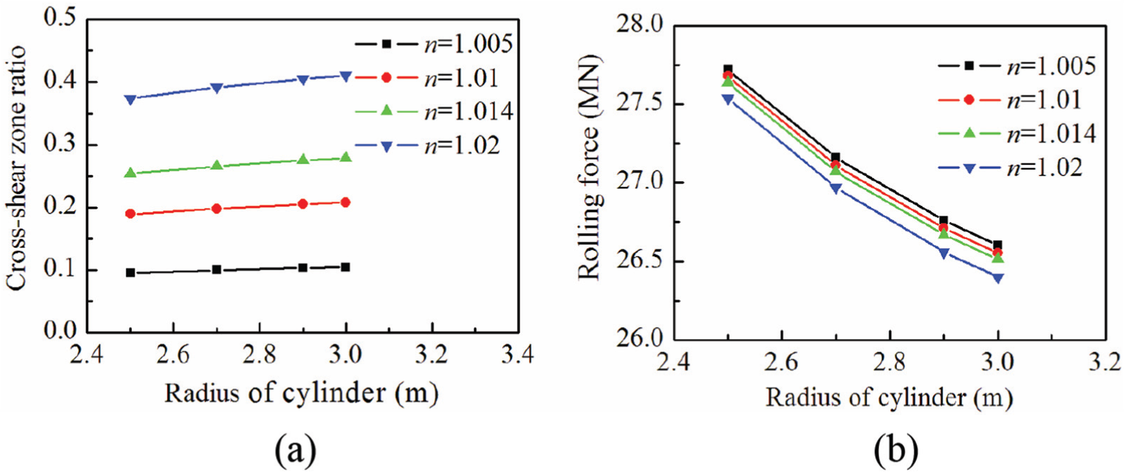
The (a) cross-shear zone ratio and (b) rolling force under various speed ratios.
In Figure 9, the cross-shear zone ratio and rolling force under various upper roll radii are studied for different reductions. It is seen that by increasing the upper roll radius, the asymmetry of the upper and lower rolls is reduced, thus the cross-shear zone becomes smaller and the cross-shear zone ratio decreases. However, the rolling force increases with the increase in the upper roll radius as there is an increase in contact length. Besides, by increasing the reduction, the cross-shear zone ratio and rolling force are increased.
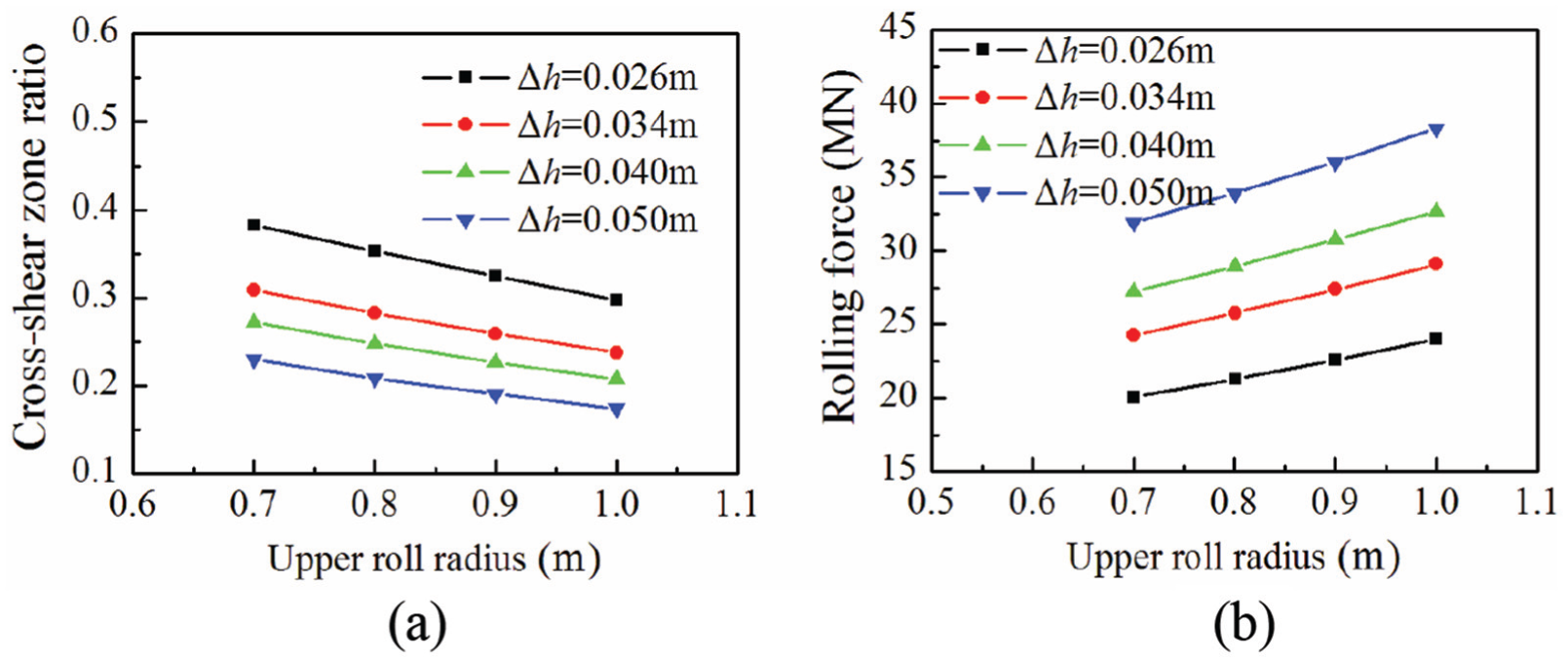
The (a) cross-shear zone ratio and (b) rolling force under various upper roll radii.
The effect of the exit thickness on the cross-shear zone ratio and rolling force for different speed ratios is depicted in Figure 10. It can be seen that by increasing the exit thickness, the cross-shear zone ratio increases gradually. When the speed ratio is larger, the increasing trend is more remarkable. Moreover, the rolling force reduces with the increase in the exit thickness and speed ratio.

The (a) cross-shear zone ratio and (b) rolling force under various exit thicknesses.
Conclusion
In this article, a theoretical model for evaluating the rolling force and cross-shear zone ratio in large-cylinder rolling is developed, and a quick analytical solution is derived based on the improved slab method. Unlike the existing models, the uneven shear stress and different contact lengths on the upper and lower interfaces have been taken into account, and the roll gap is divided into four slabs. A good agreement among the proposed model, experimental, and finite element results has been observed. The influence of speed ratio, roll radius, exit thickness, and cylinder radius on the cross-shear zone ratio and rolling force has been studied. As the roll speed ratio, exit thickness, and the radius of large cylinder increase, the cross-shear zone ratio increases, which means the shear effect is enhanced; therefore, the rolling force decreases. With increase in the upper roll radius, cross-shear zone ratio decreases, which means the shear effect is weaken, so the rolling force increases.
The proposed analytical model could expediently and rapidly predict the characteristics of large-cylinder rolling; therefore, it satisfies industrial online application.
Footnotes
Handling Editor: Jia-Jang Wu
Declaration of conflicting interests
The author(s) declared no potential conflicts of interest with respect to the research, authorship, and/or publication of this article.
Funding
The author(s) disclosed receipt of the following financial support for the research, authorship, and/or publication of this article: This study received support from the National Natural Science Foundation of China (51305388), Natural Science Foundation of Hebei Province (E2016203103), and Doctoral Foundation of Yanshan University (B946).