
Abstract
A series of problems arise when a gear pump operates at high speed, including instability of the rotor, deformation of the chamber, and wear of the journal bearing. Among all failure modes, journal bearing wear is the most serious. The wear of journal bearings of a circular arc gear pump that operates at high speed is thus presented in this article. A journal bearing that offsets the unbalanced radial force is designed by analysis of the fluid and determination of eccentricity of the gear shaft. Experiments show that the wear of the new journal bearing is effectively reduced.
Introduction
The development trend of the gear pump is that the pump is operated at high speed. However, a series of problems arise at high speed, resulting in research on the design of the tooth profile, research on processing methods, fluid analysis, and analysis of performance.1–3 Some problems that arise when a gear pump operates at high speed have been solved theoretically. However, the wear of a gear pump is difficult to analyze theoretically. Moreover, the wear of a gear pump results in instability of the rotor, damage to the pump body, and an increase in the temperature of the hydraulic oil. Mucchi E et al. 4 established a mathematical model that can be used to optimize the running-in process and to investigate the effect of wear of the pump casing. Koç E and Hooke C J 5 studied the wear of loaded floating.
In all wear of a gear pump, the journal bearings are obvious. This wear is caused by an unbalanced radial force. However, the research cited above rarely mentioned how to solve the effect of unbalanced radial force acting on a gear pump. The present paper thus designs journal bearings that offset part of the radial force. The design is verified experimentally.
Design of radial-force-compensating journal bearings
This section uses a circular arc gear pump as a basic model. The radial force is determined by the design of the teeth and obtained by establishing a mathematical model of high- and low-pressure zones. Journal bearings that offset the unbalanced radial force are then designed.
Basic model of a circular arc gear pump and journal bearing
The circular gear pump comprises a driving gear, driven gear, journal bearings, pump body, front end cover, rear end cover, and oil seal, as shown in Figure 1. A three-dimensional model of a journal bearing is shown in Figure 2.

Structure of a circular arc gear pump.

Three-dimensional model of journal bearing.
The circular arc tooth is formed by circular arc AA′, involute

Coordinate systems of the circular arc tooth.
The circular arc AA′ is expressed by 3

where R is the radius of the pitch circle, r is the radius of circular arc, and
The involute A′B′ is expressed by 3

where
The circular arc BB′ is expressed by3

where
The helical surface is then expressed by 3

where

Circular arc helical gear.
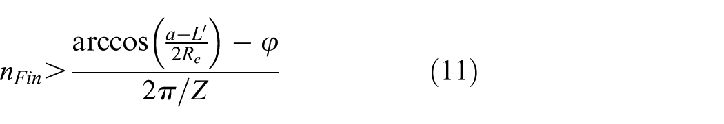
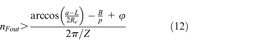
Determination of number of teeth of high- and low-pressure zones
The radial force is generated by the effect of high-pressure hydraulic oil on the surfaces of the gears, and the number of teeth of the high- and low-pressure zones must therefore be determined. The zones of high and low pressure depend on the outlet, inlet, and chamber. The mathematical model of the inlet and outlet is shown in Figure 5.

Mathematical model of the inlet and outlet.
The length of the connect edge in the low-pressure zone is denoted

where
The outlet is mathematically expressed by

where a is the central separation of the gears,
The inlet is mathematically expressed by
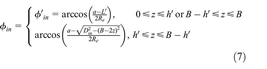
where


where
When

When

When

When

Calculation of the radial force and eccentricity
Because the tooth surface used in this article is helical, the infinitesimal tooth surface is studied to facilitate the calculation. The normal vector and unit normal vector for a helical surface are

The radial force is

The radial forces generated by the hydraulic force in directions x and y are


where

Distribution of hydraulic pressure.
In Figure 6, the pressures of high-pressure zone and low-pressure zone are

Three-dimensional model of a hydrostatic journal bearing.
Figure 8 shows a force diagram of a hydrostatic journal bearing. The overall radial force Fr is

where

Force diagram of a hydrostatic journal bearing.
The high pressure in the pressure chamber acts on the gear shaft, producing an upward force

where
The force

The new radial force is

The maximum radial forces under different pressures are obtained using the above equations. Values are given in Table 1.
Maximum radial forces and eccentricity under different pressures.

Eccentricity is caused by the weight of the gear shaft and hydraulic pressure, and it generates dynamic pressure when the gear pump rotates, as shown in Figure 9(a).

Position of the gear shaft center and journal bearing radially unfold.
Figure 9(b) shows the unfold of the journal bearing along the radial direction. The oil film force is calculated using the Reynolds equation, expressed as

where

The flow chart of calculation of eccentricity.
Figure 11 shows the center position of gear shaft under the different outlet pressures. The results show the offset distance increase with outlet pressures.

The center of gear shaft under different pressures.
Simulation of fluid
This section conducts numerical simulation to study the internal pressure of journal bearings because it is difficult to obtain the real pressure in a pressure chamber experimentally. The oil film model of the hydrostatic journal bearing is shown in Figure 12. The position and eccentricity of oil film are obtained by Table 1 and Figure 10. The design parameters of the pressure chamber are given in Table 2.

Oil film model of the hydrostatic journal bearing.
Geometrical parameters of journal bearings.

The bearing inlet pressure is set to the pressure of the high-pressure zone, and the rotational speed of the oil film at the inner wall is set to the rotational speed of the gear shaft. The oil film at the outer wall maintains a constant state. The computation domain and mesh are shown in Figure 13. The mesh type is tetra/mixed. There are 2,750,355 cells in total. The outlet pressure is set to standard atmospheric pressure of 0.1 MPa. The computation model is laminar and oil is incompressible. A pressure-based solver and implicit method are employed.
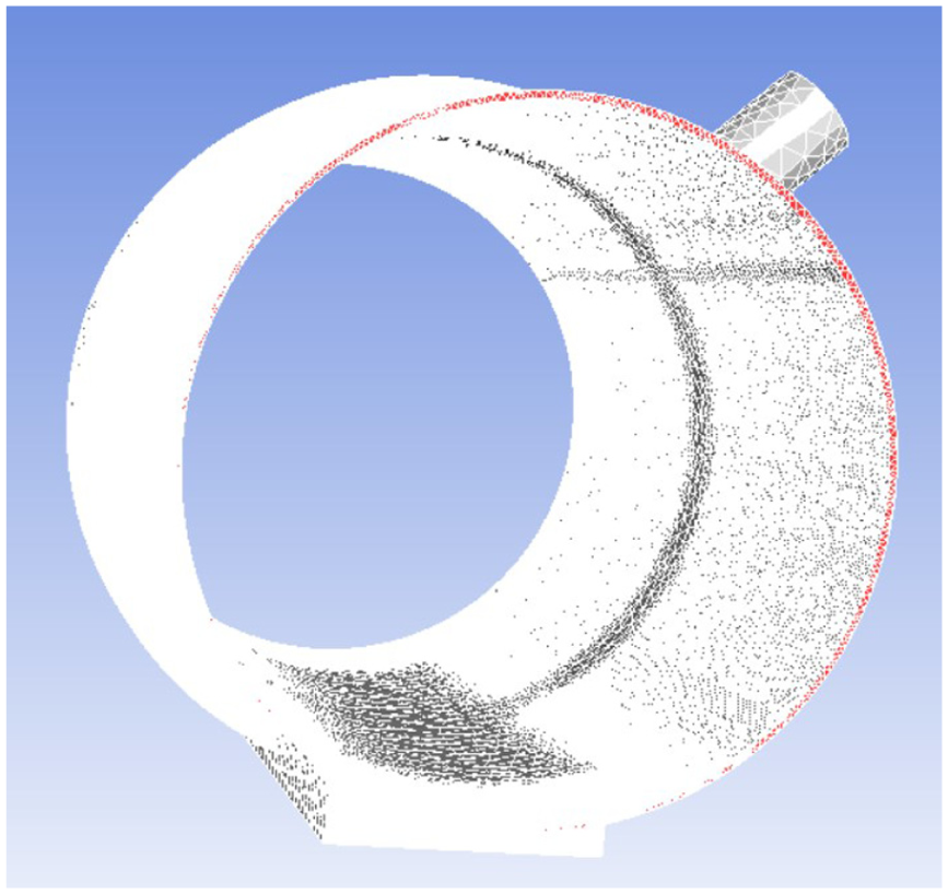
Mesh of the hydrostatic journal bearing.
Figure 14 shows contours of pressure at different inlet pressures. The pressure drops are caused from inlet into pressure chamber.

Contours of static pressure at different inlet pressures: (a) 1.5 MPa, (b) 2 MPa, (c) 2.5 MPa, and (d) 3 MPa.
Figure 14 shows the pressure drops when the inlet pressure of the journal bearing is 1.5, 2, 2.5, and 3 MPa. The pressure chamber is designed according to the simulation results.
Comparison experiments of radial-force-compensating journal bearings
Experiments were carried out to verify the effect of the journal bearing with a pressure chamber. The experiment prototype and journal bearing with a pressure chamber are shown in Figure 15.
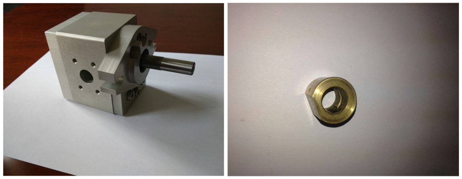
Prototype of a circular arc gear pump.
Figure 16 shows the test platform. The rotational speed is obtained by a torque speed sensor and the different gear pump outlet pressures are produced by adjusting a throttle valve and overflow valve. The flow rates of the prototype at different rotational speeds are obtained by a flow sensor.

Test platform.
Figure 17 shows the flow rates of the journal bearings with and without a pressure chamber at different rotational speeds. The outlet pressure of test pump is 2 MPa. The curves of the flow rate basically coincide when the rotational speed is lower than 8000 r/min.

Flow rates with and without the pressure chamber.
Figure 18 shows the volume efficiency of gear pump with and without journal bearing pressure chamber. The curves of the volume efficiency basically coincide when the rotational speed is lower than 8000 r/min.
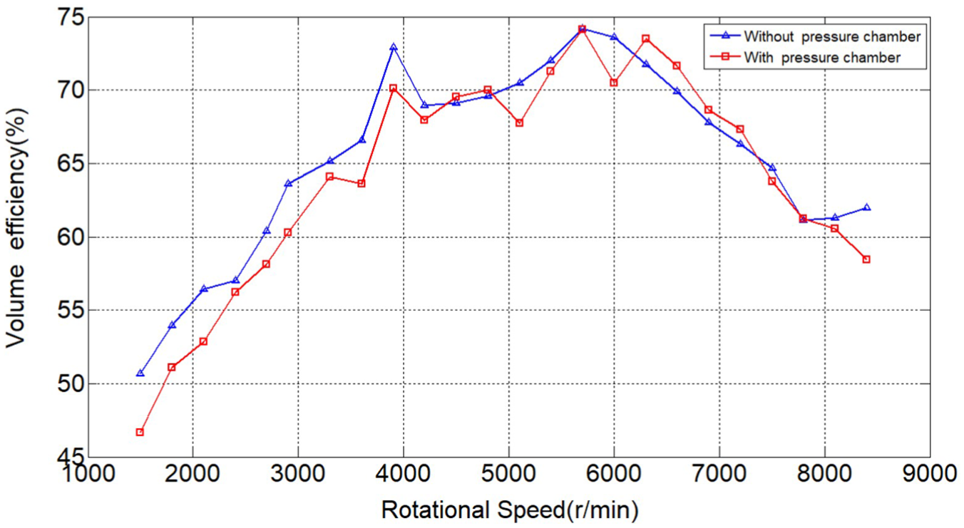
Volume efficiency of gear pump with and without journal bearing pressure chamber under different rotational speeds.
Figure 19 shows the wear of journal bearings with and without a pressure chamber. The wear of the journal bearing without a pressure chamber is greater than that of the journal bearing with a chamber. Moreover, the gear shaft stuck when using the journal bearing without a pressure chamber at a rotational speed of 7500 r/min. The above analysis thus shows that the new journal presented in this article performed well.
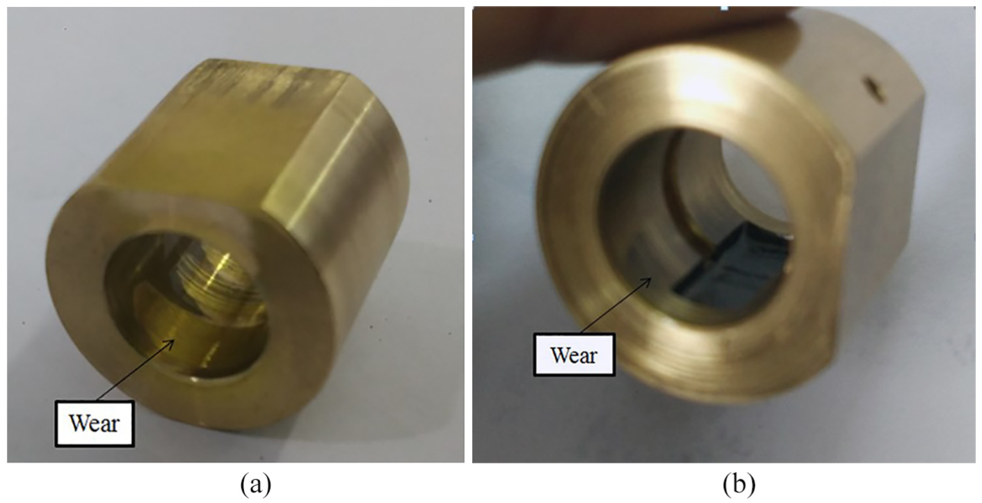
Journal bearings with and without a pressure chamber. (a) without a pressure chamber and (b) with a pressure chamber.
Conclusion
This article studied the radial force and radial force fluctuations of a circular arc gear pump and developed a new journal bearing that offsets the unbalanced radial force and reduces wear. The design of the journal bearing is based on the radial force. The radial force is mathematically obtained by determining the high-pressure and low-pressure zones and the number of teeth in high-pressure and low-pressure zones. In addition, the fluid analysis of journal bearings was carried out. Results show that there are pressure drops from the inlet into the pressure chamber, and the pressure drops increase with increasing inlet. Finally, an experiment was conducted to compare journal bearings with and without a pressure chamber. Results show that wear is effectively reduced for the journal bearing with a pressure chamber.
Footnotes
Handling editor: Francesca Russo
Declaration of conflicting interests
The author(s) declared no potential conflicts of interest with respect to the research, authorship, and/or publication of this article.
Funding
The author(s) received no financial support for the research, authorship, and/or publication of this article.