
Abstract
In this article, the flow rate and leakage of circular arc–involute–circular arc gear pumps were investigated. Models of transverse and radial leakage patterns of the pump were also developed. The leakage characteristics were studied under different outlet pressures and rotational speeds. The observed results show that leakage decreases and volumetric efficiency increases with an increase in the rotational speed. Contrarily, the leakage increases and efficiency decreases as the outlet pressure increases. The eccentricity caused by radial force, the tip in the radial direction, and the center of rotor was obtained by Reynolds equations. The effect of eccentricity on leakage was assessed in this article. The results show that leakage increases as eccentricity increases. The experiments on circular arc gear leakage were also carried out in this article. The results show that the leakage was obtained by considering the eccentricity was more closer to the experimental results.
Keywords
Introduction
Gear pumps are widely used in automotive, aerospace, and other fields. Gear pump development trends are moving in a number of directions, including high-pressure applications, high rotational speed application, and pump miniaturization. 1 The problems associated with leakage, rotor stability, and seals are amplified at higher speeds and pressures. The leakage modes for gear pumps are transverse leakage, radial leakage, and gear mesh leakage. 2 Leakage increases as the outlet pressure increases. Within the literature,1,3–6 the leakage of gear pumps with involute tooth profiles has been investigated. As a result of the very small clearance between the tip of each tooth and the chamber, the model of radial leakage of involute gear pump is assumed to occur in planes that are parallel to the tip surface.7,8 However, the involute tooth profile exhibits a trap-oil phenomenon. Therefore, the circular arc–involute–circular arc gear is introduced. 9 Meanwhile, there is eccentricity whereby the actual center of the rotor strays from the theoretical center because of the radial force caused by a combination of hydraulic, gear mesh, and oil-film forces. 10 This eccentricity influences leakage and is caused by the variation of the rotor center.
The purpose of this article is to establish a leakage model for a circular arc–involute–circular arc gear pump and to study the influence of outlet pressures and rotational speeds on leakage with and without eccentricity.
The circular arc–involute–circular arc gear pump model
The structure of the circular arc–involute–circular arc gear pump is shown in Figure 1. The primary components are the driving gear, driven gear, journal bearings, body, shaft seal, and circlips.

Structure of a circular arc–involute–circular arc gear pump: (a) External structure of pump. (b) Internal structure of pump.
Hydraulic oil is transported from inlet to outlet as the driving gear rotates. The leakage is caused by the clearance
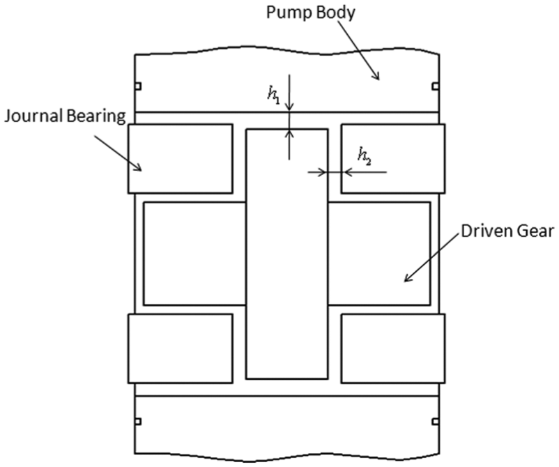
Clearance of a circular arc–involute–circular arc gear pump.
The “circular arc–involute–circular arc” tooth profile is developed by circular arc

The tooth profile of circular arc–involute–circular arc gear.
The equation of circular arc
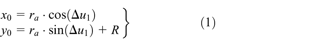
where
The equation of involute
where
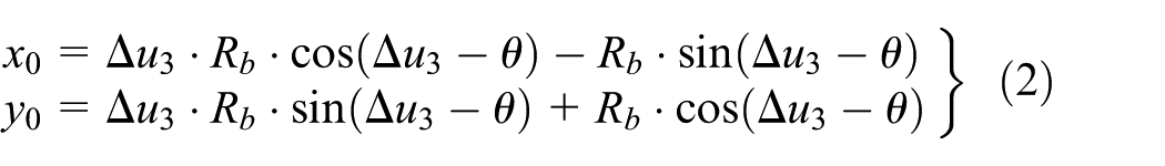
The equation of circular arc

where
In this article, the radius
The flow rate and leakage
Flow rate
In order to ensure the flow rates remain stable, the relationship between face width, modulus, and helical angle has been established by designing and optimizing tooth profile parameter. The specific derivation process is as follows.
The rotational angle of driving gear is obtained as follows

As the transverse ratio is 1 in this article, the rotational angle of driven gear is obtained by

Figure 4 shows the relationship between meshing point and gear center. Suppose z-axis is direction along axis direction (z-axis) of gear, the volumes dV1 and dV2 are obtained by the rotational of driving gear and driven gear
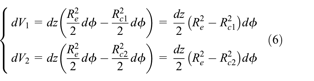
where

The relationship between meshing point and gear center.
According to Figure 4, the displacement at unit angle is


where
According to equations (8)–(10), equation (7) can be rewritten as

The displacement of gear pump is obtained by equation

As tip radius
where
According to the equations above and tooth profile parameters, the relationship between face width, helical angle, and modulus is

where
The radial force increases with face width
Equation (14) is rewritten as
The displacement is simplified as equation (16)

where
The flow rate is

where
Leakage model of gear pump
The radial leakage model
The radial leakage of the circular arc–involute–circular arc gear pump is caused by the clearance between the gear tip and the chamber, as shown in Figure 5(a). The clearance is shown in Figure 5(b).
Radial leakage mathematical model of circular arc-involute-circular arc gear pump. (a) Coordinate system model of gear tip clearance. (b) Simplified model of gear tip clearance.
The fluid is incompressible Newton fluid, and the component of the equation of motion in the x direction 11 is
The equation can be simplified as 11

where
Boundary condition is set by

where
The fluid velocity in x direction is obtained as

where
The radial leakage is obtained by

where
The end face leakage model
Transverse leakage is not only related to the clearance but also to the pressure zones. In Figure 6 pressure distribution on the gears varies with the rotation angle and is computed by arithmetic processing. The pressure of the high-pressure zone is

Range of pressure.
Transverse leakage is caused by the clearance

The model of end face leakage.
The mathematical model of end face leakage is 11

where
The effect of eccentricity
During operation, the center of the gear moves away from the theoretical center; this eccentricity is caused by the radial and the oil-film forces. The eccentricity causes the clearance between the gear tip and the chamber to change, as shown in Figure 8.

Radial force and offset of rotor.
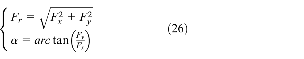
The radial force is caused by hydraulic and mesh forces, which are caused by hydraulic oil and the gear mesh, respectively. According to the author’s previous work, the radial forces in the


where
The radial force caused by hydraulic oil is defined by
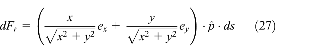
where

where


where
Figure 9 shows the eccentricity of gear 2, which is caused by radial force. The clearance between the tip of the teeth and the chamber is obtained by

where

Eccentricity of the center of gear 2.
In Figure 9, the teeth between high pressure and low pressure are

where i=1, the radial clearance is h1′′.
The eccentricity of the center of gear 2 is also affected by the oil-film force caused by the journal bearings and rotor. The oil-film force is calculated by the Reynolds equation

where
The results of simulation
This section shows the leakage with and without eccentricity under the different rotational speeds and outlet pressures. Table 1 shows the tooth profile and oil characteristic parameters.
The tooth profile and oil characteristic parameters.

Figure 10(a) and (b) shows the center position of the driving gear under different rotational speeds when the outlet pressure is 5.8 MPa. Figure 10(b) is the detail view of illustration of driving gear center position. Similarly, Figure 11(a) and (b) shows the center position of the driven gear under different rotational speeds when the outlet pressure is 5.8 MPa. Figure 11(b) is the detail view of illustration of driven gear center position.

Center of driving gear under different rotational speeds: (a) illustration of driving gear center position (b) detail view of illustration of driving gear center position.

Center of driven gear under different rotational speeds: (a) illustration of driven gear center position (b) detail view of illustration of driven gear center position.
Figures 10 and 11 show the offset distance of the gear center as it changes with rotational speeds. The rotational speeds decrease with an increase in the offset distance.
The volumetric efficiency

where
Figure 12 shows the theoretical volumetric efficiency under the different pressures and rotational speeds. The volumetric efficiencies increase with rotational speeds. The rate of rise of volumetric efficiency tends to be stable with rotational speeds increase. The volumetric efficiency decreases with outlet pressure. In Figure 12,
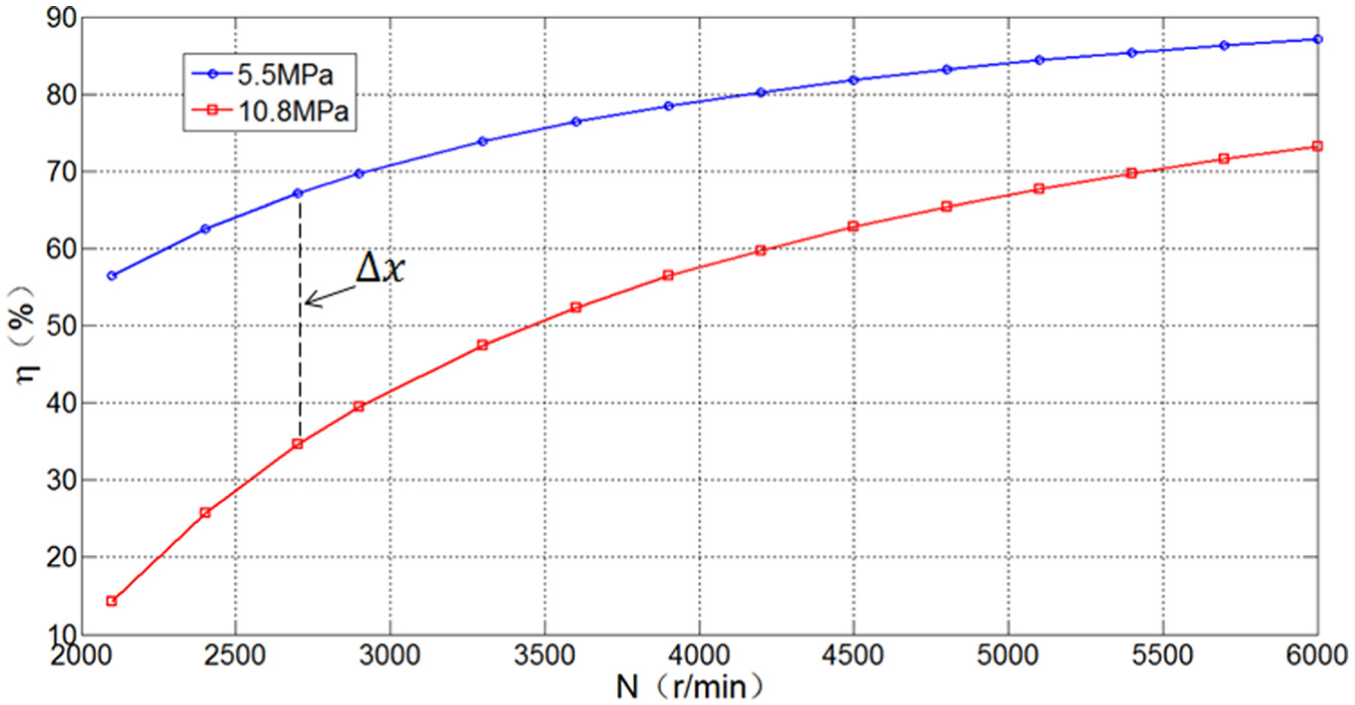
Theoretical volumetric efficiency under the different outlet pressures and rotational speeds.
Experiment and results
Experiments were carried out to verify the model of leakage with eccentricity. The test platform is shown in Figure 13, and the experiment prototype and circular arc gear are shown in Figure 14.

Test platform.
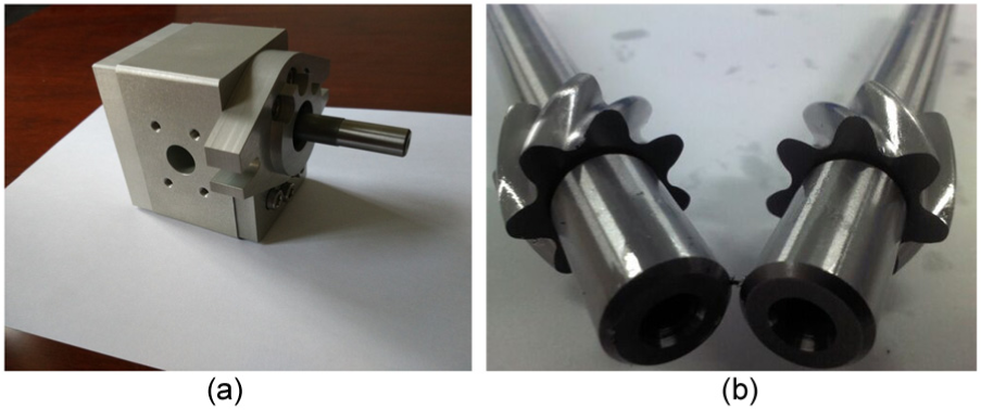
Experiment prototype and circular arc gear.
The rotational speed is obtained by a torque speed sensor, and the different gear pump outlet pressures are produced by adjusting a throttle valve and overflow valve. The flow rates of the prototype at different rotational speeds are obtained by a flow sensor.
The results of experiment are shown in Figure 15. In Figure 15, the outlet pressure is 5.8 MPa, and the growth trend of volumetric efficiencies with rotational speeds is consistent with the theoretical value. The leakage is more close to the experimental values when the effect of gear eccentricity is considered. However, the volumetric efficiency which is obtained by experiment is lower than theoretical calculation. The reason is wear between journal bearing end face and gear end face, which leads to the end face clearance increase and accelerated gear pump leakage.

Theoretical and experimental volumetric efficiency.
Conclusion
A leakage model of a circular arc–involute–circular arc gear pump has been established, and the effect of gear eccentricity on leakage is discussed in this article. The main results obtained in this study are as follows:
The effects of eccentricity, rotational speeds, and outlet pressures on leakage have been investigated. The results show that the leakage increased with outlet pressures and decreased with rotational speeds.
The effect of eccentricity, caused by oil-film and radial forces, on leakage has been studied in an operational gear pump. The eccentricity increases with rising outlet pressures and decreases with an increase in the rotational speed. Leakage was also observed to increase as eccentricity increases.
The volumetric efficiencies of circular arc gear pump are studied in this article. The volumetric efficiencies increase with rotational speeds, and the rate of rise of volumetric efficiency tends to be reduced with an increase in rotational speeds.
The comparisons of experiment of gear pump leakage are carried out in this article. The experimental results show the leakage is more close to the experimental results when the effect of gear eccentricity is considered.
Footnotes
Academic Editor: Jianqiao Ye
Declaration of conflicting interests
The author(s) declared no potential conflicts of interest with respect to the research, authorship, and/or publication of this article.
Funding
The author(s) received no financial support for the research, authorship, and/or publication of this article.