
Abstract
Flexible stretch-stamp forming is a sheet metal forming method derived from flexible stretch forming and multi-point forming, aimed at solving wrinkling defects of large skin parts especially with complex curvatures, prone to occur in the later type of forming processes. To help understand the forming principle and forming characteristics of flexible stretch-stamp forming, a large sheet metal part with wavelike surface was selected as the study object and extensive numerical simulations have been conducted using a general commercial finite element software. The main processing parameters of pre-stretching force and wrapping force, respectively, exerted by horizontal and sloping cylinders on forming quality were investigated in detail. Finally, experiments were conducted to estimate the forming performances of flexible stretch-stamp forming.
Introduction
Wrinkling and shape deviations due to springback are two main forming defects in sheet metal forming processes, which restrict their applications in many fields. With rapid industrial development, urgent demands have been put forward on increasing the flexibilities of forming processes and devices for the purpose of improving forming quality. Under such background, a variety of innovative flexible forming processes have been proposed in automotive, aeronautic, and architect industrial fields.
Stamping is one of the most common manufacturing processes in producing three-dimensional skin parts, since it has the following advantages of high production efficiency, precision, consistency, and applicability for mass production. However, due to high tooling cost, setting time, and long processing time for the manufacture of dies, the traditional stamping process is no longer applicable for rapid prototyping or for the production of thin sheet metal components especially with complex geometry. Under such background, flexible forming processes have been developed and deeply studied. In the present study, it should be mentioned that the flexible forming processes are the processes with discrete tool to distinguish those using deformable forming medium such as rubber.1–3 In 1960s, Nakajima 4 built a reconfigurable die with numerous wires and explored its applications in press working, compression molding, die-casing. Later, a concept of multi-point forming (MPF) was proposed by Li and co-workers 5 wherein the conventional stamping dies are replaced by two sets of multi-point dies (MPDs). MPF has gained a lot of attention in the past few decades. Li and co-workers6–11 carried out systemic and deep research of the forming process and its application of MPF. Quan et al. 12 studied the influence on sheet metal formability of using elastic cushions in multi-point bending process. Abebe and co-workers proposed multi-objective 13 and reliability-based robust 14 optimization techniques to reduce wrinkling and dimpling defects in MPF. Moreover, a concept of reconfigurable tooling for flexible fabrication was proposed. 15 Hardt andcoworkers16–18 explored a discrete die mechanical design with the purpose of producing sheet metal parts rapidly. The machine automatically adjusts the die pins to the desired positions, clamps them into a rigid tool, and serves as a forming press. In addition, a thin layer of thermoplastic, called an interpolator, was used to suppress dimples on the workpiece.
Sheet metal stretch forming is mainly used in aeronautics to produce skin parts, since it has the following advantages: low tooling cost (only male tools are needed), short manufacturing cycle, simple processing, and low springback. However, it is only suitable for producing parts with medium curvatures. To meet the demand of forming parts with different size or shape using only one set of forming tool, the discrete die has been introduced into the stretch forming process. Cai and co-workers19–22 proposed a new flexible sheet forming process named multi-point stretch forming (MPSF) and conducted systematic research, in which the solid die in traditional stretch forming is substituted by a matrix of punch elements with hemispherical tips, that is, MPD. Later, Li et al. 23 proposed a forming process of multi-gripper flexible stretch forming (MGFSF), in which Pascal’s law of multi-cylinder hydraulic system, strain hardening, and minimal resistance force of the material are employed.24,25 Wrinkling or the problem of conformability of sheet metal to the desired shape is prone to occur when forming workpieces with small transverse curvature radius, since the sheet metal in MGFSF conforms to the shape of the forming die under longitudinal tension and transverse compression of itself. Therefore, although MGFSF has been used successfully in producing large skin parts with medium curvatures, it is inapplicable to produce large skin parts with small or complex curvatures.
In the study, the authors introduced a forming process of flexible stretch-stamp forming (FSSF) on the bases of MGFSF and MPF, aimed at solving wrinkling defect in producing large skin parts with strong (small radius) or complex curvatures. It should be noted that FSSF, MGFSF, and MPF are sheet metal flexible forming processes. However, FSSF could effectively suppress wrinkling, improve forming quality, and afford a wider application compared to the later forming processes. The main purpose of this article is to help understand the forming principle and characteristics of FSSF through the analyses of the forming and unloading processes of a wavelike surface part using finite element (FE) analysis. The influence of the processing parameters of pre-stretching and wrapping forces, respectively, exerted by horizontal and sloping hydraulic cylinders, on forming quality of the simulated parts was investigated. Finally, experimental validations were conducted to estimate the forming performance of FSSF.
Forming apparatus
FSSF is a forming process derived from MGFSF and MPF, aimed at producing large skin parts with strong or complex curvatures. The FSSF apparatus used in the study is shown in Figure 1, which is composed by two pairs of clamping mechanisms in conjunction with three rows of hydraulic cylinders on each side, a pedestal, a portal frame, and two sets of digital controlled MPDs. The clamping mechanism consists of a clamping cylinder, a piston, two grippers and a clamping body as shown in Figure 2, similar to that presented in Wang et al. 22 Each clamping mechanism is used together with three cylinders that arranged in horizontal, sloping, and vertical directions. The cylinders in the same row are controlled by a common electromagnetic direction valve to make them produce the same tensile force during the forming process. The clamping mechanisms can make real-time movement adjustment during the forming process, making the sheet metal conformed with the desired shape easily.

FSSF apparatus.

Schematics of (a) the clamping mechanism and (b) the gripper.
Forming principle and FE modeling
Forming principle
Dimpling is one of the particular characteristics in forming processing using MPD (discrete rigid tool composed by a matrix of punch elements closely packed in a container), as the deformation would be strongly localized at the interfaces between punch elements and sheet metal. In order to suppress dimples in the workpiece, polyurethane rubbers are placed on each side of the sheet metal. A typical FSSF process is shown in Figure 3, which includes the following stages:
MPDs generating: the enveloping surfaces of MPD are generated using self-developed software, on the basis of target shape of study object taking the thickness of sheet metal and elastic cushions into account. The schematic of this stage is shown in Figure 3(a).
Pre-stretching: clamp the sheet metal with the clamping mechanisms first, and then, stretch the sheet metal by the pre-stretch force exerted by horizontal cylinders, which is shown in Figure 3(b).
Wrapping: wrap the sheet metal around the lower MPD with the wrapping force, exerted by vertical cylinders or sloping cylinders or a combination of both, as shown in Figure 3(c).
Stamping: press the upper MPD using a double action cylinder to make the sheet metal conformed to the shape of the lower MPD completely. The schematic of this stage is in Figure 3(d).
Unloading: lift the upper MPD up with the double action cylinder, and unload the pressure in the multi-cylinder hydraulic system and reset the cylinders to their initial positions (as shown in Figure 3(e)).
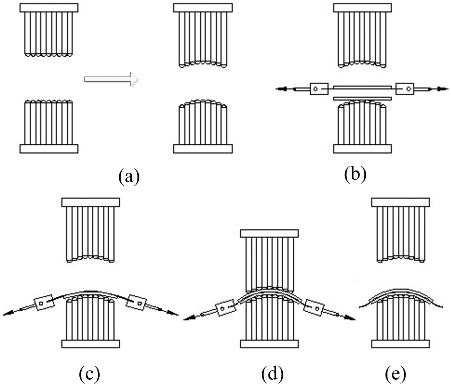
A typical FSSF process: (a) MPD generating, (b) pre-stretching, (c) wrapping, (d) stamping, and (e) unloading.
FE modeling
Material model
The mechanical behavior of the material is described by an elastic–plastic model, in which the elasticity is taken to be isotropic and the plasticity is assumed to be anisotropic. The Hill’48 yield criterion can be written as 26

where

where
Mechanical properties of cold rolled deep-drawing steel St14.

In sheet metal forming applications, anisotropic yield behavior is usually defined on the basis of Lankford’s r-value, that is, the ratio between plastic strain along the width direction and through thethickness. 28 However, Hill’s anisotropic yield behavior in Abaqus is modeled through the use of yield stress ratios, Rij. Therefore, strain ratios should be converted to stress ratios to make them available in Abaqus, and the relevant mathematical relationships are given as follows 29


A typical hyperelastic material of polyurethane rubber was adopted as the elastic cushion, under the consideration of its excellent wear and corrosion resistance. In Abaqus, there are several forms of strain energy potentials available to model rubberlike materials. When only one set of test data (uniaxial, equibiaxial, or planar test data) is available, the Marlow form is recommended. 29 Therefore, the Marlow form was adopted in the study. The form of Marlow strain energy potential is

where

where

Nominal stress–strain relationship of polyurethane rubber.
FE model
A complex curvature part is selected as the study object, which has a wavelike curve parallel to the stretching direction, as shown in Figure 5. The enveloping surfaces of the MPDs are generated on the basis of the surface of target shape using 3D design software CATIA, taking the thickness of elastic cushions and sheet metal into account. The initial size of the sheet metal is 2030 × 1250 mm with a thickness of 1 mm. To suppress dimpling defect, two pieces of 10 mm polyurethane rubbers were placed on each side of the sheet metal.

Target surface of the workpiece.
The FE model of FSSF was established with Abaqus/Explicit, as shown in Figure 6. Due to symmetry, only a quarter of the clamping mechanisms, MPDs, sheet metal, polyurethane rubbers, and hydraulic cylinders were modeled, and the symmetry boundary conditions were prescribed to the parts of sheet metal and polyurethane rubbers. The MPDs, clamping bodies, and grippers were modeled with rigid elements of R3D4, since which were undeformed during the forming process. The sheet metal was meshed using S4R elements with approximate size of 5 × 5 mm, using five Simpson integration points through the thickness and reduced integration with one integration point per element as well as the effective hourglass control techniques to perform hourglass stabilization. The polyurethane rubbers were modeled using four layers of C3D8R solid elements through the thickness, and the reduced integration with one integration point per element and the effective hourglass control technique was adopted to avoid spurious deformation during the simulation process. Hydraulic cylinders were modeled with Axis & Cardan section connector elements for the purpose to simulate their movements in real forming process. In addition, it should be noted that the pre-stretching and wrapping force was exerted by horizontal and sloping cylinders, respectively. Moreover, the pre-stretching and wrapping force was loaded from 0 to the desired value with an increasing amplitude, respectively, in the pre-stretching and wrapping stages.

(a) FE model of FSSF (1/4 symmetry) and (b) distinct zones of sheet metal (1/4 symmetry).
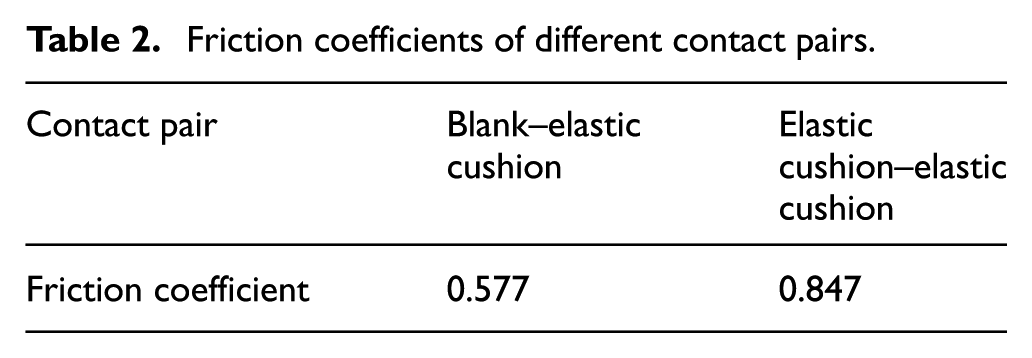
General contact algorithm was adopted and the frictional behaviors at the interfaces of contact pairs were assumed to follow Coulomb’s model. Friction tests were performed on a vertical universal friction and wear testing machine MMW-1A 30 with test geometry of a rotating washer on stationary ring under rotary sliding mode, and the friction coefficients of different interfaces are listed in Table 2. In addition, as there was no relative sliding motion, Rough friction formulation was adopted to model the friction behavior at the interface between the grippers and the sheet metal, which is a type of surface interaction to model tangential friction behavior with no slip displacement between two contacting surfaces, that is, a friction formulation specifying an infinite coefficient of friction to the interface. In addition, it should be noted that the forming processes from stage 2 to stage 4 were performed in Abaqus/Explicit, and the springback analyses were conducted by importing numerical results from Abaqus/Explicit into Abaqus/Standard.
Friction coefficients of different contact pairs.
Results and discussion
Influence of pre-stretching force
In the section, five levels of pre-stretch forces were selected to investigate their influences on forming results. The simulation results show that severe wrinkles appear in the forming zone after springback, in the cases with the pre-stretching force smaller than 15 kN, as shown in Figure 7. To briefly study the influence of pre-stretching force on forming precision, only the simulation data in the other three cases, that is, with the pre-stretching force equal to 15, 25, and 35 kN were investigated.

Light maps of the simulated parts under different pre-stretching forces: (a) 5 kN and (b) 10 kN.
The springback value contour plots along the z-axis are illustrated in Figure 8. It is seen from an overall perspective, it is obvious that the springback values in the case with the pre-stretching force equals to 25 kN are smaller than those in the other two cases. To quantitatively analyze the influence of pre-stretch force on forming error, Figure 9 gives the springback value curve along the denoted lines OC and AB denoted in Figure 6. It is seen that the springback value shows different trend along lines OC and AB in the forming zone, which demonstrates that the pre-stretching force has a complex influence on forming precision of the workpiece. It is also found that the curve fluctuates strongly in the interval form 0 and 200 in the case with the pre-stretching force equals to 15 kN, which indicates that wrinkling appears in this region. Moreover, the global error contour plots under different pre-stretching forces are given in Figure 10, and it is seen clearly that the case with the pre-stretching force equals to 25 kN results in smaller forming error.

Springback value contour plots under different pre-stretching forces: (a) 15 kN, (b) 25 kN, and (c) 35 kN.

Springback value distributions along the denoted lines: (a) along line OC and (b) along line AB.
Global shape error contour plots under different pre-stretching forces: (a) 15 kN, (b) 25 kN, and (c) 35 kN.
From the above analyses, it can be drawn that the pre-stretching force has a complex influence on forming precision. Specifically, the wrinkling in the middle edge region of the forming zone could be effectively eliminated by increasing the pre-stretching force. However, a higher pre-stretching force would also result in larger springback value in the forming zone. Therefore, an appropriate pre-stretching force should be chosen under the consideration of suppressing wrinkling defect and reducing springback.
Influence of wrapping force
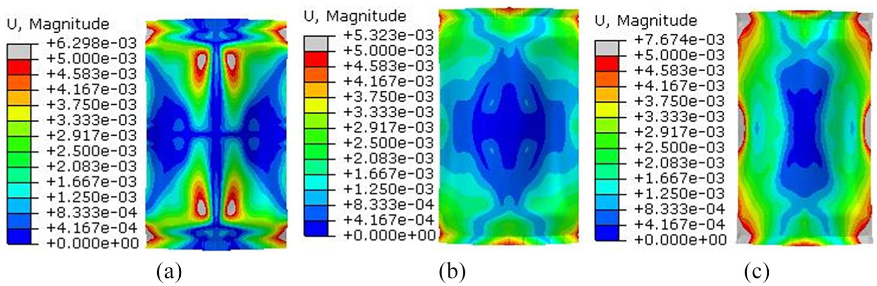
Wrapping force is another main processing parameter in FSSF. Four levels of wrapping force, i.e., 5, 10, 15, 20 kN were selected to investigate their influence on the forming quality, under the condition with the pre-stretching force equals to 25 kN. The springback value contour plots along the z axis under different wrapping cases are given in Figure 11. It is seen that the value is mainly located in the interval between −3.0 and +3.0 mm, in each case of the wrapping force. Specifically, it is noted that the cases with the wrapping force equal to 10 and 15 kN result in smaller deviation error than the other two cases. Furthermore, the global shape error contour plots of the formed parts are given in Figure 12, which show the same trend with the springback value contour plots along the z axis.

Springback value contour plots under different wrapping forces: (a) 5 kN, (b) 10 kN, (c) 15 kN, and (d) 20 kN.

Global shape error contour plots under different wrapping forces: (a) 5 kN, (b) 10 kN, (c) 15 kN, and (d) 20 kN.
To quantitatively study the influence of wrapping force on forming quality, the springback value curves are given in Figure 13. It can be seen clearly that the curves fluctuate strongly in the cases with the wrapping force equal to 15 and 20 kN along the line OC as well as in the case with wrapping force equals to 5 kN along line AB, which indicates that wrinkling defect probably appears in the workpiece. In addition, it should be noted that the case with the wrapping force equals to 15 kN results smaller deviation error than the other three cases. It is known that the wrinkling defect is prone to occur in the edge regions of the workpiece. Therefore, the in-plane max. principle stress curves along line OC are presented in Figure 14. The curves demonstrate that severe stress fluctuation occurs in the case with the wrapping force equals to 5 kN, demonstrating that material instability or wrinkling appears in this region.
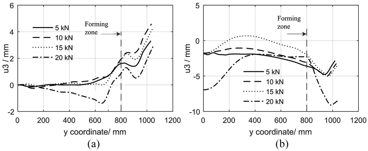
Springback value distributions along the denoted lines: (a) along line OC and (b) along line AB.
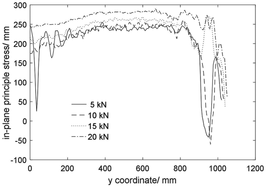
In-plane max. principle stress curves along the denoted line OC.
From the above analyses, it can be drawn that a lower wrapping force may cause wrinkles in the edge regions of the workpiece, and an overlarge wrapping force would cause higher deviation error. Therefore, a medium wrapping force should be chosen under the consideration of reducing springback and suppressing material instability. For this study, the pre-stretching force equals to 25 kN together with the wrapping force equals to 10 kN can be considered as a pair of optimal processing parameters to form the desired surface part.
Experimental validations
Both experiments of MPF and FSSF have been performed with self-developed apparatus. The upper and lower MPDs are composed of 40 × 30 closed punch elements, respectively, with one punch cap plugged into the end of each punch element. The cross section of the punch element is 40 × 40 mm, and the radius of the punch cap is 30 mm. The height of each element is digitally controlled by one electrical motor, and the desired enveloping surfaces of MPDs are generated under consideration of the thickness of polyurethane rubbers and metal sheet. Two pieces of polyurethane rubber are placed on each side of the sheet metal for the purpose of suppressing dimples in the workpiece. The geometrical parameters of sheet metal and polyurethane rubber are the same with those in FE model. It should be noted that the pre-stretching and wrapping force are exerted only in FSSF experiment test, and the relevant values are 25 and 10 kN, respectively. Figure 15 shows the workpieces formed by MPF and FSSF. It is clearly seen that FSSF could effectively eliminate wrinkling defect in the middle edge regions of the workpiece, which manifests that FSSF has superiority in producing large skin parts with complex curvatures compared with MPF.
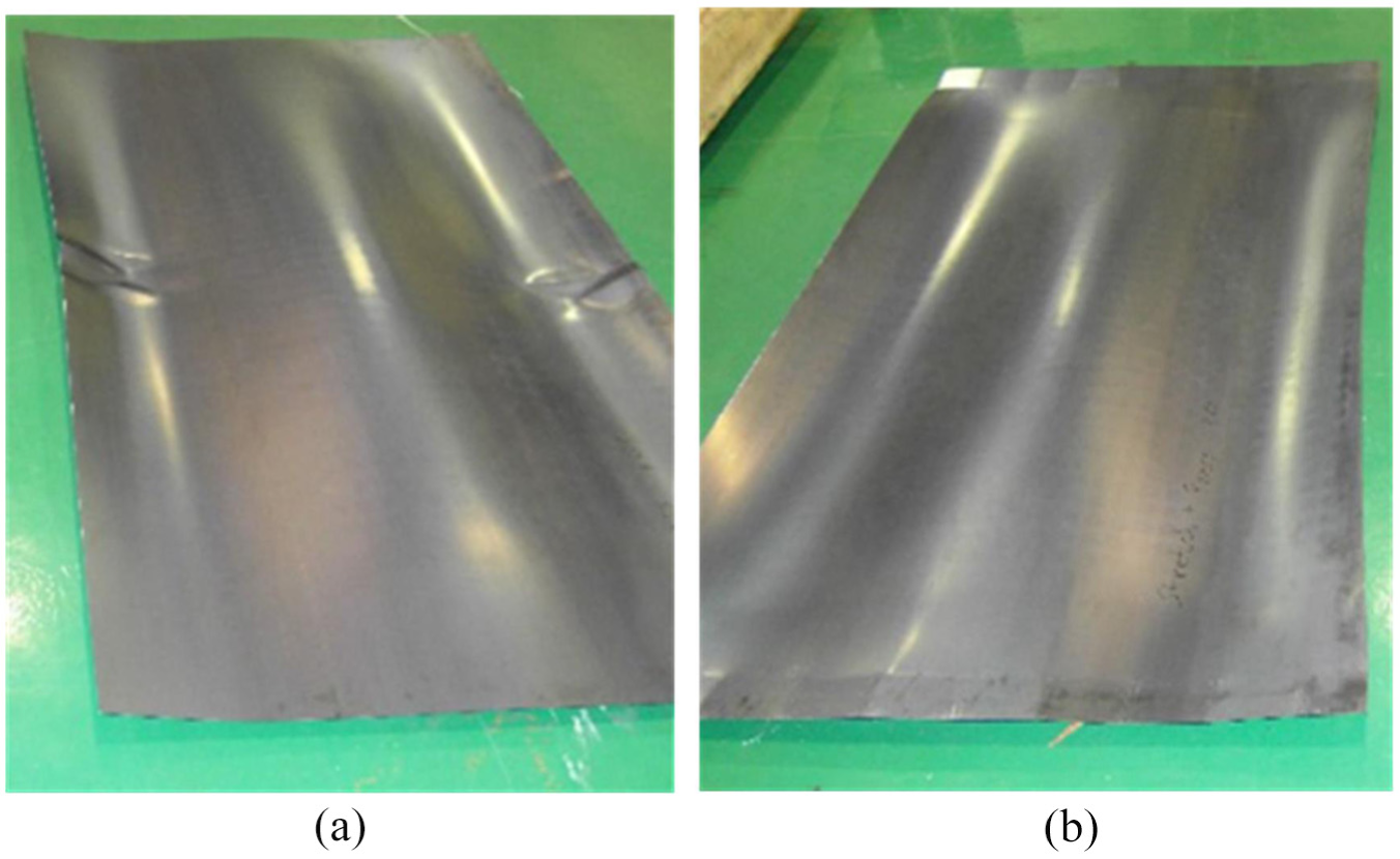
Workpieces formed by different forming processes: (a) MPF and (b) FSSF.
Conclusion and future work
In this article, the forming principle and forming characteristics of FSSF are introduced. Furthermore, the processing parameters of pre-stretching and wrapping forces on forming quality were detailedly researched by FE simulation. Finally, experimental validations were conducted to estimate the forming performance of FSSF. The main conclusions are the following.
The simulation results reveal that pre-stretching and wrapping forces are two major processing parameters in FSSF. More specifically, the pre-stretching force has complex influence on the forming quality, i.e., a larger pre-stretching force could effectively eliminate the wrinkling defect on one hand, but would also decrease the forming accuracy on the other hand. Therefore, the pre-stretching force should be chosen under the consideration of suppressing wrinkling defect and reducing springback. On the other side, a lower wrapping force would result in wrinkling defect or material instability and an overlarge wrapping force would cause higher deviation error. Therefore, a medium wrapping force should be chosen under the consideration of suppressing wrinkling defect and reducing springback.
Finally, experimental validations were conducted to evaluate the forming quality of MPF and FSSF. The results demonstrate that FSSF has superior performance in suppressing wrinkling defect for large sheet metal parts compared with MPF. Ongoing studies include the thickness and hardness of polyurethane rubbers on dimpling, tribological and deformational behaviors of polyurethane rubbers during the forming process, and accuracy detection and springback compensation algorithms on forming precision.
Footnotes
Handling Editor: Daxu Zhang
Author’s Note
Rui Li is now affiliated with Changchun Ruiguang Technology Co., LTD.
Declaration of conflicting interests
The author(s) declared no potential conflicts of interest with respect to the research, authorship, and/or publication of this article.
Funding
The author(s) disclosed receipt of the following financial support for the research, authorship, and/or publication of this article: The work was supported by the Youth Project of Hubei Province Department of Education (Q20172603).