
Abstract
Incremental sheet metal forming is an evolving process, which is suitable for the production of limited quantities of sheet metal components. The main advantages of this process over conventional forming processes are reduced setup cost and manufacturing lead time, as it eliminates the need of special purpose dies, improves formability, reduces forming forces, and provides process flexibility. The objective of this work is to investigate a new hybrid-forming process, which intends to combine incremental sheet metal forming with deep drawing process and has been named as “incremental stretch drawing.” A number of setups and fixtures were developed to carry out experiments to achieve incremental stretch drawing and understand the mechanism of the process. This process addresses some of the challenges of incremental sheet metal forming, that is, limited formability in terms of forming depth, especially at steeper wall angles and subsequent thinning of sheet. It is observed that the proposed process is able to reduce thinning as much as about 300%, considering same forming depth for incremental sheet metal forming and incremental stretch drawing processes. Improvement in formability, in terms of forming depths, also has been observed to be near about 100% in particular cases.
Introduction
Incremental sheet metal forming (ISF) is a recently evolved dieless forming process, which has introduced new possibilities in the domain of sheet metal fabrication. Conventional forming processes require huge investments on high-end machines and tooling. Therefore, to recover the high investment, these processes are apt only for mass manufacturing. Due to the dynamic nature of the market, there is a pressure on sheet metal industry to produce variety of components within limited period of time and resources. Therefore, incremental sheet forming, which does not require die or specialized machine tools has fetched huge attention of the industry. With the controlled movement of a simple indenting tool, a wide range of three-dimensional (3D) shapes can be formed directly from the computer-aided design (CAD) model by moving the tool along an optimized path and trajectory. This process is suitable for small batch production as well as in fabricating complex geometries as described by Allwood et al. 1 A self-contained description to ISF can be found in the keynote paper by Jesweit et al. 2
The ISF process has some limitations; like it generates small forming depths, particularly at steeper wall angles; and thus is not good for achieving near-vertical wall angles, as well as large forming depths. Researchers like Mirnia et al. 3 and Babu et al. 4 have done multiple studies both numerically and experimentally to assess the limitations of ISF.
Forming in multiple stages is also explored by several researchers like Young and Jeswiet 5 and Liu et al. 6 Unfortunately, multistage ISF is accompanied by several issues which are yet to be sorted out. 7 Several authors like Silva et al., 8 Hussain 9 , and Manco et al. 10 have worked on the effect of tool size and trajectory on ISF. It was observed from the literature that by modifying tool shape and trajectory, the deformation mechanism can be influenced and altered. Recently, Adams and Jeswiet 11 have formulated a standard methodology based on case studies to make implementation of ISF user-friendly. Still, the process needs extensive improvement in order to become a mainstream technology.
This work aims to address this challenge and propose a solution to the problem of achieving large forming depths at steeper wall angles. The work originated to find out whether the integration of deep drawing with ISF would solve this problem.
As deep drawing is devoid of such limitations, thus, based on the inferences made from literature, authors have proposed formulation of hybrid deformation mechanism of ISF and deep drawing to combine the best of both the processes.
In order to investigate whether efforts to combine ISF with deep drawing have been made or not, study of previous work in the domain of ISF was carried out. Emmens et al. 12 described in detail the work on the technology of ISF. Their paper described the history of ISF process with a focus on technological developments. They have extensively covered patents on ISF also. Their paper gives a good idea not only about ISF process but also presents processes related to ISF, like the work on spinning and hammering done by Bewlay and Furre 13 and Vihtonen et al., 14 respectively. Kim and Park 15 presented a study on the effect of process parameters in ISF that gives a quick and brief idea about the important parameters that affect the component quality in ISF. A critical review of the models available to predict the material behavior and the tests needed to identify the models’ material parameters in sheet metal forming is described by Bruschi et al. 16 Apart from this, several attempts have been made to analyze formability of sheet metal components in ISF, for example, the work done by Filice et al. 17 Martins et al. 18 proposed the theory of single-point incremental forming (SPIF), and Isik et al. 19 characterized the formability limits by fracture in sheet metal forming and showed that fracture-forming limit (FFL) for SPIF is identical to that determined from conventional sheet formability tests. Malhotra et al. 20 predicted the occurrence of fracture in SPIF using fracture model combined with finite element analyses. They also compared the deformation mechanism in SPIF to that in conventional forming process and showed that the local nature of deformation is primarily responsible for increased formability in SPIF.
Although ISF has vast range of applications from the fields of automobile to medical sciences, and it has variants like hammering, spinning, and two-point ISF, to the best of our efforts, it is difficult to find related literature where ISF has been tried to combine with other processes like deep drawing and stretching. A few efforts were made toward combining above-mentioned processes; for example, Shima et al. 21 were the first to propose incremental deep drawing process. Although the work proposed by them did present deep drawing incrementally, but the process did not facilitate stretching. Lim et al. 22 presented a work combining stretch forming with deep drawing. TalebAraghi et al. 23 presented their research work on a new hybrid-forming process, that is, combined incremental sheet forming and stretch forming. Mitukiewicz et al. 24 proposed a method to form sheet materials using gas blow-forming process at elevated temperatures.
So, after extensive study of literature, it has been observed that out of ISF, stretch forming, and deep drawing, a combination of stretching and deep drawing is already attempted; furthermore, stretch forming and ISF have also been combined. That leaves an avenue to combine ISF with deep drawing, so that the benefits of both ISF and drawing can be combined and exploited simultaneously. This requires a new setup and fixture(s), which would allow material to flow like deep drawing in conjunction with incremental sheet forming. The new hybrid process is referred as incremental stretch drawing (ISD) here.
Right since the evolution of ISF process, the major challenge in ISF has been to enhance the formability in terms of forming depth, especially at steeper wall angles along with reduction in sheet thinning, which is an inherent consequence of any stretch-forming process. Thinning results in cracks and puts a limit on ISF. In ISF, sheet metal blank is clamped at its periphery and the tool incrementally stretches the sheet to form the desired geometry. ISF is quite similar in its nature to stretch-forming process.
Limitations of stretch forming are obviously associated with ISF also. The primary cause of thinning is stretching, and to reduce stretching, the only way is to allow the material to flow toward the deformation point or in case of symmetrical components, allow the material to flow toward the center. Thus, the desired process has some process characteristics of deep drawing also. Therefore, the proposed process methodology makes an effort to combine ISF and deep drawing to counter the problems of thinning and limited formability.
There are a few challenges in the proposed process also. Two major issues are wrinkling in deep drawing and tendency of the sheet to rotate due to tool movement, and thus its rotation about the spindle axis. Thus, the challenge is to facilitate the material to flow toward the center, and at the same time, the sheet is supported in such a way that it does not wrinkle or rotate and stays in place.
Principle/Underlying mechanism
Of late, a considerable interest has been developed among research fraternity to understand the deformation mechanism of ISF. To mention a few, Cui et al. 25 proposed an analytical model for strain distributions and validated the deformation mechanism of incremental forming process with the help of numerical simulations and experiments. An analytical model of SPIF to describe the localized deformation mechanism that considered both bending and strain hardening had been proposed by Fang et al., 26 while Li et al. 27 provided an analytical model to predict tangential force based on the energy method and compared the predicted tangential forces with the experimental results. Madeira et al. 28 had also discussed techniques and studies to comprehend plastic flow and failure mechanism of ISF process. However, being a relatively recent process, a robust analytical model of the proposed ISD process is yet to be developed. Meanwhile, based on preliminary experiments, a qualitative interpretation of the process is made here.
The mechanism for deformation is due to combined effect of shear, stretching, drawing, and bending. In SPIF, it has been observed that higher rate of damage causes earlier growth of material instability due to higher shear strain. During ISD process, when smaller diameter tools were used after the large diameter tool, an early plastic strain and deformation had set in the sheet. This strain and deformation increases uniformly and gradually, which leads to uniform spreading of shear strain and deformation along the walls of the formed component. The failure of the component in the case of ISD is due to both shear and local bending. It was observed that shear is more prominent on the inner side of the sheet, while bending is significant on the outer side.
Methodology
Keeping process requirements and limitations discussed in the former section in mind, efforts have been made to formulate a standard methodology for ISD. A large number of preliminary experiments were conducted to gauge the effectiveness of the proposed concept. It was observed that the desired material flow direction for axisymmetric-shaped components is radially inward.
Various tool path strategies that include constant depth, spiral outside-in, and spiral inside-out had been tried and experimented upon. The strategy that provided the best results was adapted for further investigation of the proposed phenomenon. The proposed strategy which was most successful in preliminary experiments is a multi-step process that involves consecutive drawing and incremental forming of a metal sheet.
The methodology developed for this investigation can be formally divided into following three steps:
Drawing with large-sized tool;
Drawing and ISF with medium-sized tool (inside-out tool path);
ISF with small-sized tool (outside-in tool path).
Figure 1 shows a simple flowchart on the proposed methodology and Figure 2 shows the schematic representation of the proposed process.
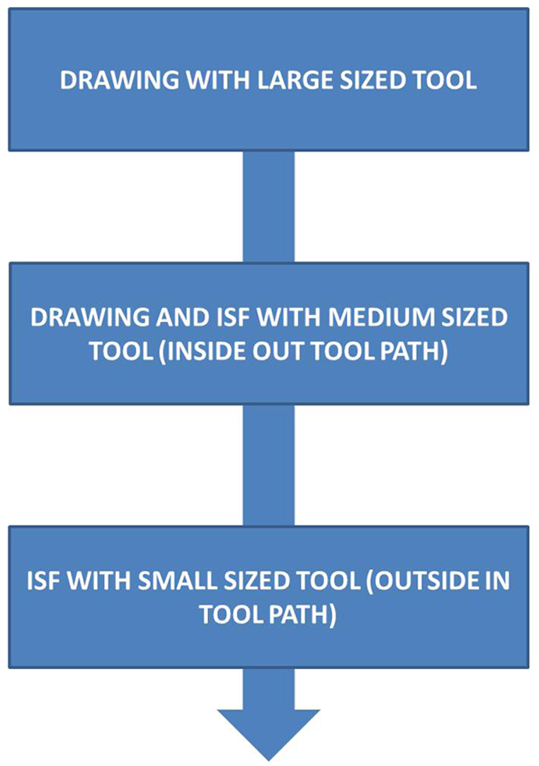
Flow of the process.
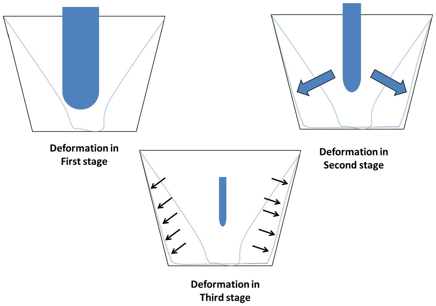
Deformation mechanism of ISD.
Step 1: Drawing with large-sized tool
In order to achieve drawing, it is important to use deformation tool of large size. That is why for the first setup of experimentation, a tool of diameter 60 mm had been used. This tool was used in the same way as a punch in deep drawing is used. For forming with a large punch, the dominant deformation mechanism is tensioned along the component wall. In the first step, the tool moves only in vertical downward direction, that is, along Z-direction till the depth of the component to be made was achieved. Forming depth in the first step equals to the actual depth of the desired part.
In our case, for tool diameter of 60 mm and maximum component diameter of 100 mm, maximum depth of forming achieved, without cracks, was 36 mm but with severe wrinkles. This tool was used to achieve forming depth up to 28 mm with curable wrinkles. The tool was later passed over the wrinkles, as shown in Figure 3.
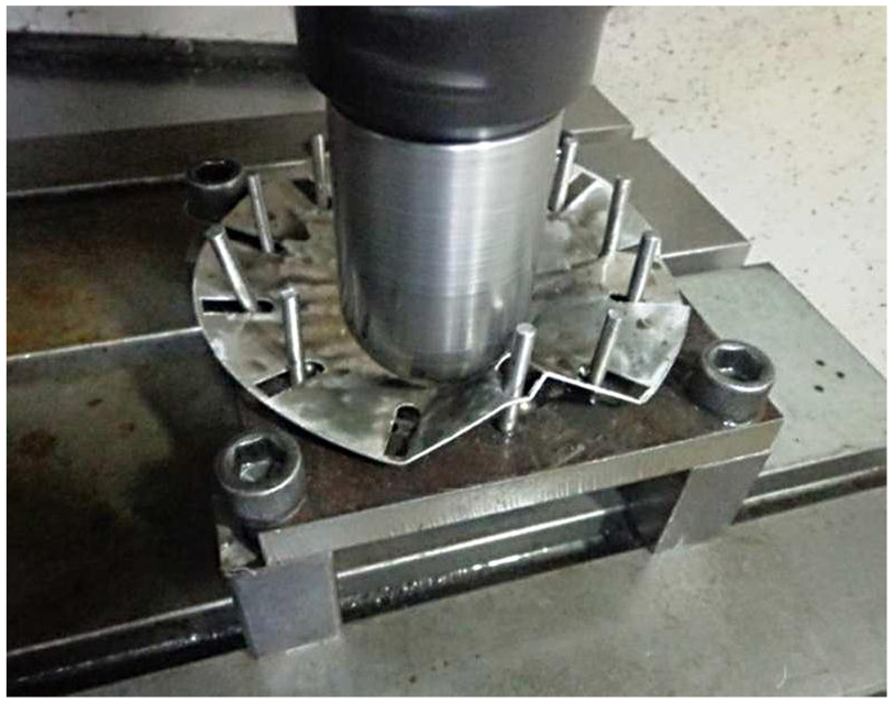
Drawing with large-sized tool.
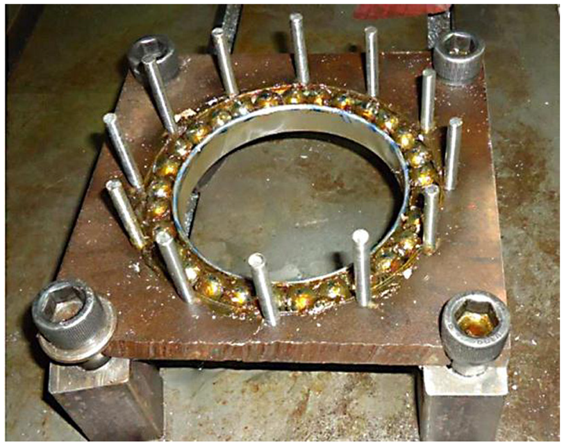
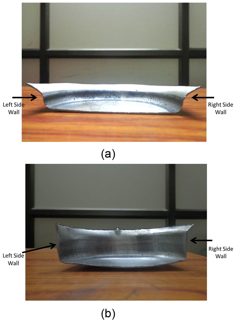
The inner boundaries of the slots were clearly shifted inward, as shown in Figure 4 when an operation similar to deep drawing (but not true deep drawing) was performed with a large tool (here, diameter of 60 mm). Due to vertical rods placed in the slots, the blank did not rotate. Figure 4(a) and (b) shows blank sheet before and after first stage of deformation (drawing), respectively.
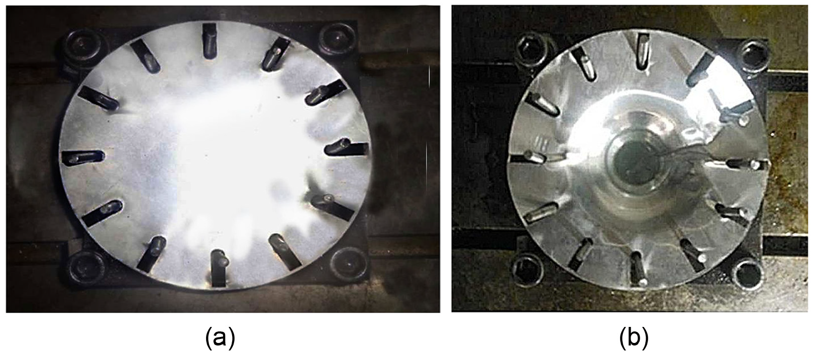
Deformation of sheet due to incremental stretch drawing process: (a) sheet before drawing and (b) sheet after drawing.
Step 2: Drawing and ISF with medium-sized tool (inside-out tool path)
After the drawing was complete, a tool of 30 mm diameter was used to get a near net shape of the given CAD model. This tool was moved along an inside-out tool path. The tool movement started from the center of the base and ended at the outermost point of the component, as shown in Figure 5. After this step, the component acquired almost the same geometry as of the given CAD model.
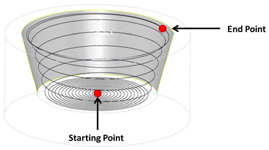
Inside-out tool path.
Step 3: ISF with small-sized tool (outside-in tool path)
It is a known fact that small-sized tools lead to better formability and accuracy in geometry, so in order to improve accuracy in the component geometry, finally, a tool of small diameter (13 mm) was used along the spiral outside-in tool path, as shown in Figure 6(a) and (b).
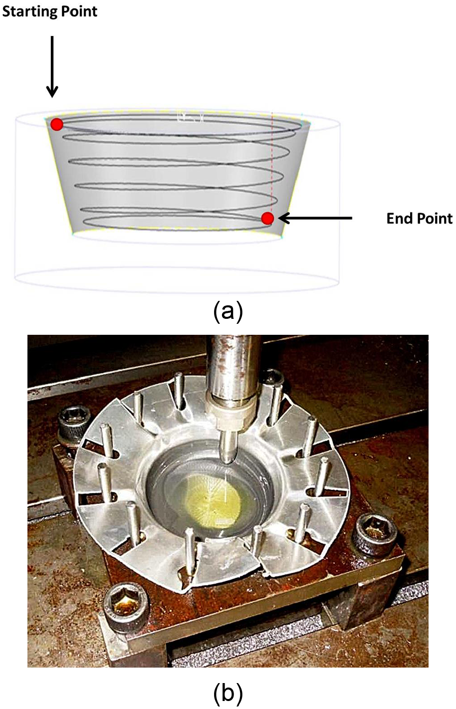
(a) Outside-in tool path and (b) ISF with small-sized tool.
Development of an experimental setup for ISD
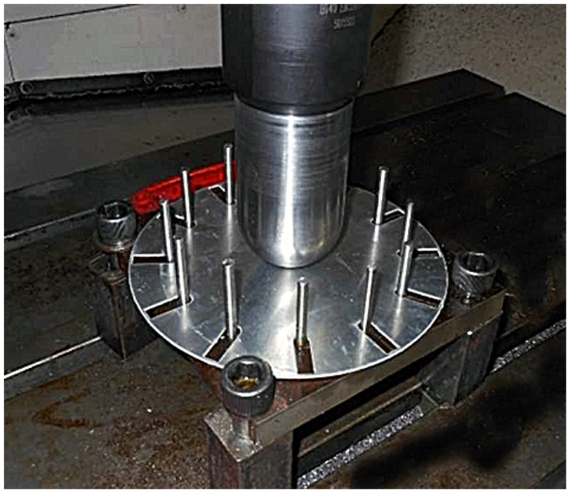
As the proposed process is in formative stage, dimensions of the metal sheet, tools, and fixtures used have been taken according to the limitations and ease of experimentation on the computer numerical control (CNC) machining center available in the laboratory. After a set of preliminary experiments, a design of the setup was finalized and used for subsequent experimentations, although this design also has vast scope for improvement. Setup fabricated with aforesaid design is shown in Figure 7.
Blank with radial slots placed on the fixture under the large tool.
Experimental setup
All the experiments had been performed on a three-axis vertical CNC milling center available in the laboratory. Contrary to incremental sheet forming process where sheet is clamped at its periphery, in the proposed process (ISD), the sheet was not clamped. As the sheet metal blank had to be held in its place allowing only desired inward radial movement, a new fixture was required. This was a great challenge, as the rotating forming tool when plunged into the sheet had the tendency to rotate the blank also. So, to stop its rotational tendency and simultaneously allow desired radial flow of the sheet, a fixture, as shown in Figure 7, had been proposed. This fixture consists of a metal plate having thickness of 20 mm with a hole in its center of 100 mm diameter. At a distance of 2 mm outside the hole is a groove, in which stainless-steel balls of 12 mm diameter had been placed such that tip of the ball is just 2 mm above the surface. This was done so that blank may rest on these balls only to reduce the frictional resistance and easily allow the flow of material. Apart from this, 12 thin vertical rods had been placed symmetrically outside the groove to stop the blank from rotating, as shown in Figure 8.
Fixture for supporting sheet metal blank.
Forming tools and sheet metal blank
Forming tools
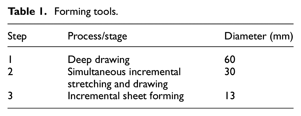
The tools used in ISD process were made using mild steel. Tool specifications are given in Table 1.
Forming tools.
Figures 9 and 10 show diagrams and actual representation of tools used in the process, respectively.
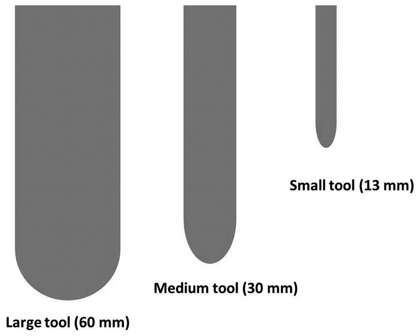
Diagram of forming tools.
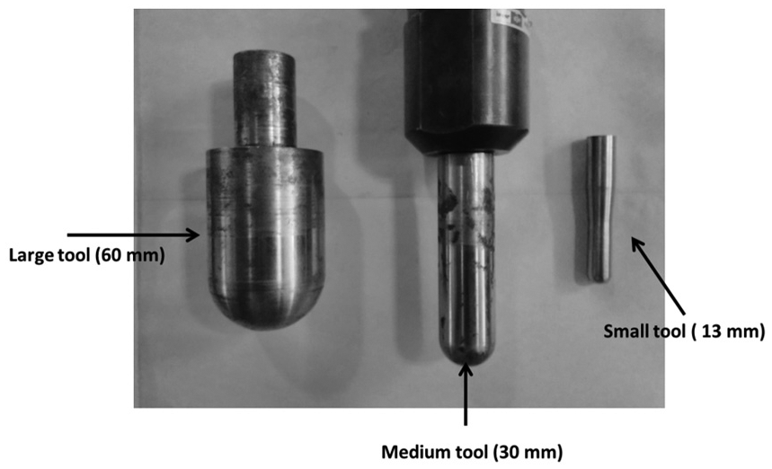
Forming tools.
Sheet metal blank
In order to facilitate ISD on the fabricated setup, the sheets had been cut in the form of circular blanks having diameter of 180 mm. To allow only desired radial flow of material and not the rotational movement, the blank has radial slots of 5 mm length cut into it, as shown in Figure 11, corresponding to the vertical rods present in the base plate fixture, as shown in Figures 7 and 8.
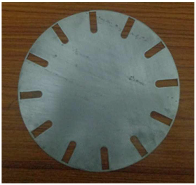
Sheet metal blank.
Results and discussions
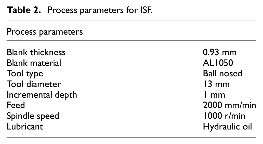
While performing experiments and even after their culmination, whole process had been observed minutely and inferences were made. This section presents and discusses the observations made and results obtained from the investigation. A few components were also formed through ISF under parameters mentioned in Table 2 for making comparative analysis.
Process parameters for ISF.
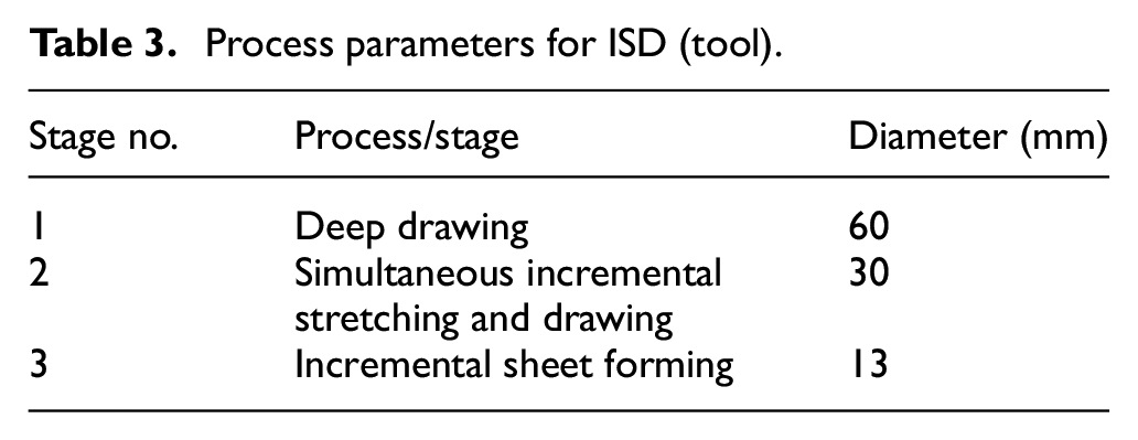
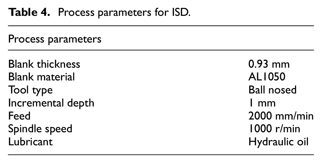
Specifications for tools used in ISD process are mentioned in Table 3. Other process parameters as used in Step 2 and 3 are mentioned in Table 4.
Process parameters for ISD (tool).
Process parameters for ISD.
Reduction in thinning
In order to measure the effect of the process on reduction in thinning of the component, the fabricated sheet metal component had been cut in two halves. To measure the thinning effect, permanent markings were made on the components and corresponding measurements had been taken. Similarly, component prepared by conventional ISF process had also been cut in two halves and measurements had been taken after proper markings. To measure the thickness of the walls of the formed components, a micrometer of least count of 0.01 mm was used. To capture the data related to 3D geometry of the component, a 3D Laser Scanner (LPX 600) was used.
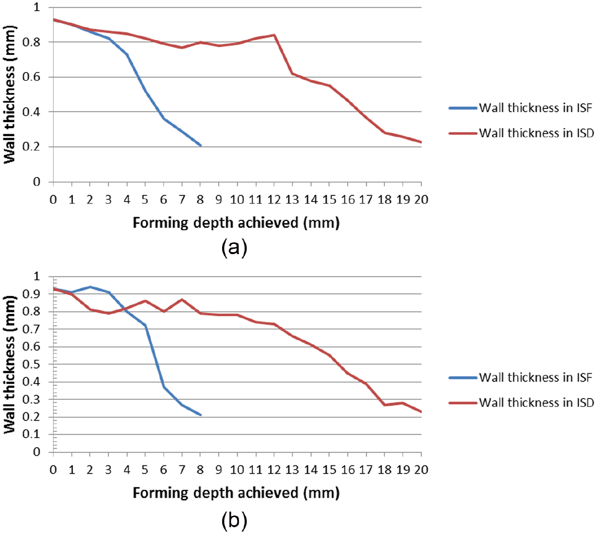
It can be clearly observed with the help of Figure 12(a) and (b) that for the same forming depth achieved, ISD produces thicker walls.
Comparison of thinning between ISD and ISF processes for (a) left sidewall and (b) right sidewall of the sectioned components.
With both the processes, the components had been manufactured at 90° wall angle, using aluminum alloy blanks of 1 mm thickness, but forming depths achieved for both the components were different. For component made by ISD process, forming depth achieved without crack was 20 mm but with ISF, cracks appeared before 10 mm. A comparison of wall thickness on the two sides of the sectioned components, as shown in Figure 13, has been presented with the help of Figure 12(a) and (b), as a plot between forming depth achieved and wall thickness. It is quite clear from the trends observed in Figure 12(a) and (b) that for both the sidewall sections of the components, ISD process not only allows more forming depths to be achieved but also reduces thinning by a significant amount. For example, from Figure 12(a), it may be observed that at forming depth of 8 mm, when cracks appear in the component fabricated using ISF process, the wall thickness is observed as 0.20 mm, while the wall thickness at the same point for component fabricated using ISD is 0.78 mm, which is an improvement of 290%.
Two sides of the sectioned component: (a) component fabricated using ISF and (b) component fabricated using ISD.
Formability (achievement of greater forming depth and steeper wall angles)
In ISD process, as thinning is less in comparison with the ISF process, larger forming depths can be achieved at steeper wall angles.
Three identical truncated cones with wall angles at 70°, 75°, and 90° were formed with ISD to study the extent of effectiveness of the process.
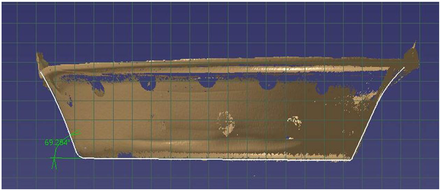
To measure the forming depth, the component was scanned with the help of a laser scanner and 3D-digitized data were stored. The captured point cloud data were imported in a CAD environment and dimensional observations were performed. For example, Figures 14 and 15 show measurement of forming depth and wall angle for component with wall angle of 70° formed through ISD.
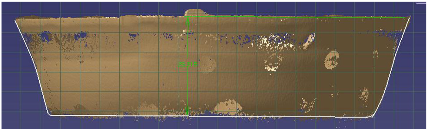
Measurement of depth using CAD tools.
Wall angle measurements by CAD tools.
To understand the improvement imparted by the process, a comparison of forming depth achieved between ISD and ISF processes for components having different wall angles has been made. Three identical truncated cones with wall angles at 70°, 75°, and 90° were also formed with ISF with parameters mentioned in Table 2 to compare ISD with ISF. The results of the comparison are shown with the help of Figure 16.
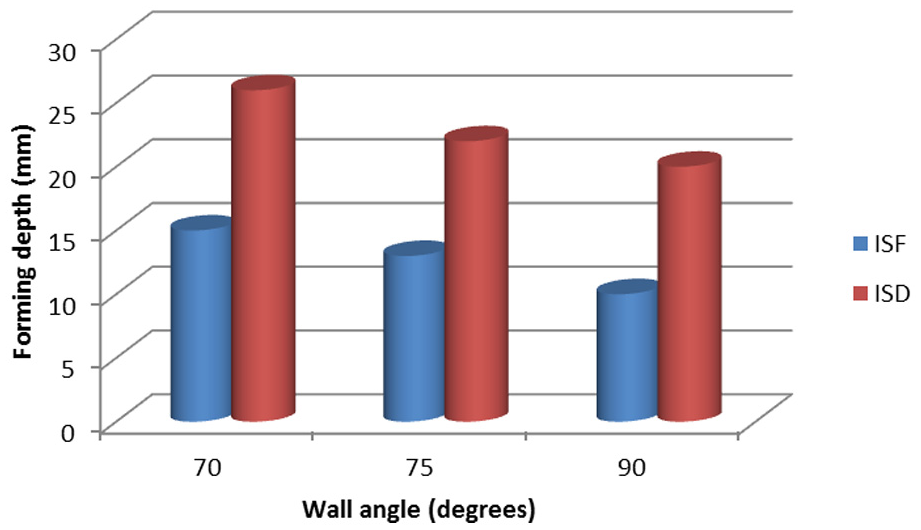
Comparison of forming depth achieved between ISD and ISF processes.
It is evident that with the help of ISD, greater forming depths and steeper wall angles can be achieved, in comparison with the ISF.
Accuracy of the formed part
To have an idea about the accuracy of the geometry produced by ISD process, wall angles of the component manufactured by the proposed process are measured and deviations from the desired wall angles are recorded. Figure 17(a)–(c) presents the actual geometry and the true wall angles (69.284°, 74.584°, and 89.326°) obtained for the desired wall angles of 70°, 75°, and 90°, respectively. Thus, better accuracy in terms of wall angles for the component manufactured by ISD process can be achieved.
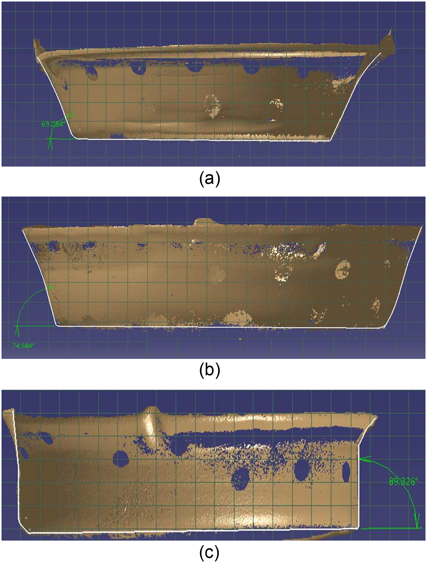
(a) Wall angles achieved with ISD process (69.28°) when desired wall angle was 70°, (b) wall angles achieved with ISD process (74.58°) when desired wall angle was 75°, and (c) wall angles achieved with ISD process (89.32°) when desired wall angle was 90°.
Material distribution
To observe the pattern of material distribution in the ISD process, a grid pattern had been made on the backside of the blank, before its deformation. The grid pattern consisted of circular dots of diameter of 5 mm. Post deformation, on observing the geometry of these circular dots, one can identify the distribution of strains developed on the sheet during the ISD and ISF processes. Figure 18 shows such grid pattern on a blank.
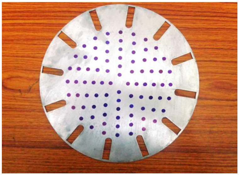
Grid pattern made on the backside of the blank.
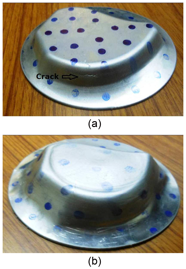
In conventional ISF process, when components are formed, tool traces its path only along the wall, and the bottom portion of the component often remains untouched, as shown in Figure 19(a). It can easily be observed from the circular dots that the wall sections have been deformed, and the bottom section of the component has remained undeformed. Whereas in ISD process, the inside-out tool path strategy, as described in the previous section, results in better utilization of the available material. As shown in Figure 19(b), circular dots of every section, whether it is wall or bottom, get deformed. Therefore, it is evident that ISD enhances the extent of material deformation as compared to ISF.
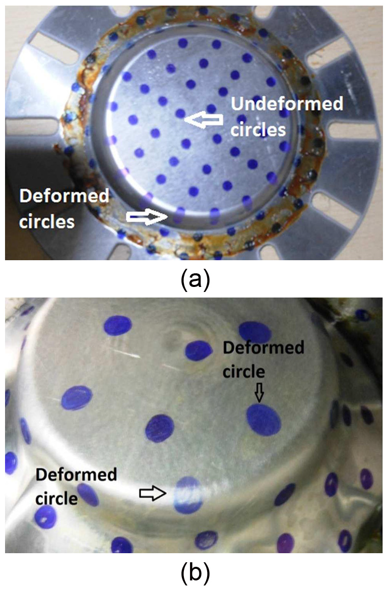
Components formed using (a) conventional ISF process and (b) ISD process.
Forming of non-symmetrical shapes
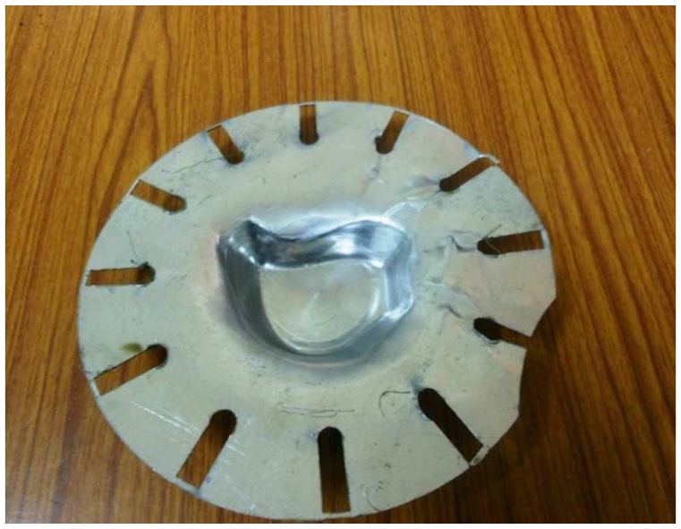
ISD can also be used to achieve non-symmetrical shapes, like one shown in Figure 20. For this particular component, the tool path strategy used is same as described above. A blank of 100 mm core diameter (leaving radial slots) and 180 mm outside diameter has been used. As shown in the figure, geometry with steeper wall angle and sharp corners has been fabricated. This component has depth of 20 mm, and efforts have been made to fabricate it with ISF process also, but with ISF process, cracks started to appear only after achieving a depth of 13 mm, as shown in Figure 21(a); whereas, complete forming depth of 20 mm has been obtained through ISD process, as shown in Figure 21(b).
Non-symmetrical shape fabricated by ISD process.
(a) Crack formed using ISF process in forming of non-symmetrical-shaped component and (b) non-symmetrical-shaped component formed without crack formation using ISD.
Conclusion
The major objective of this work is to club the deep drawing process with ISF, that is, to draw the component in an incremental manner. The reported work presents advancement in the field of ISF by opening a new door of possibilities. The results highlight that metal sheets can undergo both ISF and drawing simultaneously. ISD tries to solve the biggest limitation of ISF process, that is, thinning, as reduction in subsequent thinning improves the formability limits of the metallic sheets, that is, with ISD, larger forming depths and steeper wall angles can be achieved. Uniqueness of this new process lies in the fact that it proposes a very simplistic, less time-consuming, and economic setup which can be performed on any CNC milling machine.
The grid pattern analysis proves that improved results are because of the proper use of available material within the component, whereas in conventional ISF process, material that is available at the bottom of the deformed component often remains undeformed.
Furthermore, many of the materials that may be deep drawn by conventional deep drawing process are not used in ISF process due to lack of stretching, but ISD process opens a new set of avenues for many ductile materials to be formed in an incremental manner. This would require some modifications in the existing setup. Unlike deep drawing process, ISD can be used not only to achieve symmetrical shapes but also non-symmetrical shapes. Deep drawing does not impart work hardening in the formed components but this proposed process does. In this way, ISD counters the challenges of both ISF process and deep drawing process.
This process being in formative stage still has issues that need to be properly addressed. The larger tool used for drawing should be of comparatively similar dimensions to the desired geometry. Thus, in a sense, a specialized tool needs to be fabricated for each part. This problem can be addressed using a smaller tool (still larger than the finishing tool) and incrementally drawing the sheet at multiple regions to cover up the entire sheet. The other major challenges that need to be addressed are as follows:
To control the problem of wrinkling of sheet deformed using a blank holder as used in the case of deep drawing;
To work on materials harder than aluminum alloy. For this, modified experimental setup (machine tool) capable of exerting higher deformation forces is required;
To use the tools having roller or rotating ball at tip, and to investigate the effect of such a tool on the deformation mechanism;
To study the effect of heat in ISD process.
Footnotes
Declaration of conflicting interests
The author(s) declared no potential conflicts of interest with respect to the research, authorship, and/or publication of this article.
Funding
The author(s) received no financial support for the research, authorship, and/or publication of this article.