
Abstract
Ball screw is the driving functional component most frequently used for the precision equipment. To a certain extent, the transmission accuracy of precision equipment is affected by the position error of ball screw caused by the elastic–plastic deformation between ball and raceway under the overload impact. This article aims to investigate the precision loss of ball screw considering short-time overload impact. A novel precision loss model combining the Hertzian and Thornton contact theories is established to describe the variations in the axial deformation depths. Thus, the axial precision loss can be defined as the differential value between the initial no-loading travel variations and the loading stroke variations caused by the axial plastic deformation of raceway. Meanwhile, the maximum stress and the residual plastic deformation for four couples of ball-raceway materials are analyzed. Furthermore, the relationship between the precision loss and the elastic–plastic deformation is studied by the theoretical analysis and experiments. The results show that the position and precision is affected indeed by the contact deformation. The position and precision loss of the nut relative to the screw increases with the increase in the axial load. The results can help to provide the prediction for the precision life of ball screw operating in high-load condition.
Introduction
With the development of the extreme equipment manufacturing industry, such as high-load and high-precision equipment, the high-reliability core transmission parts are critical technical challenge for the large equipment. In the rapid development of the aerospace defense industry and deep-sea operation equipment, the transmission system with ball screw is affected by the deep-sea high pressure and the agravic impact working conditions, such as the docking of spacecraft, the opening and closing of the shuttle cabin door, the spreading and retracting of aircraft landing gear, and the swing of the deep-sea robotic arm. Thus, the requirements are presented on the bearing capacity, impact resistance, precision sustainability, and performance reliability of ball screw in the particular transmission system.
The wear, the contact characteristics, and the load distribution method of ball screw have been widely studied in previous works. MC Lin et al. 1 investigated the quasi-static contact characteristics of ball screw in the three-coordinate system. T Yoshida et al. 2 studied a new finite element model to study the uneven distribution of stress. Song and Lu 3 established a new online measuring system of ball screw movement precision, and the laser stroke error measuring instrument is used to measure the precision of the same ball screw. Wang and Lin4,5 proposed the super magnetostrictive double-nut ball screw preload system with an additional hinged lever, and the mechanical strain of giant magnetostrictive material (GMM) is converted into the preload force of ball screw. Hung et al. 6 established the impact model of the ball impact on the return pipe, and the finite element analysis method of load distribution of the return pipe was analyzed. Wei and Lin 7 developed a model to analyze the load distribution of ball screws with geometry errors, and the dynamic characteristics of ball screw considering elastic deformation and change of contact angle are analyzed. C Braccesi and L Landi 8 established a plastic contact analysis model of ball and raceway surface with plastic deformation, which can be used to study the deformation of raceway surface more accurately. Li et al. 9 studied the finite element model considering the induction hardening parameters on the hardened layer to improve the distribution of the hardened layer and avoid potential defects. Zhou et al.10,11 proposed a comprehensive wear prediction model, which combined the modified Archard wear theory 12 and Hertzian contact theory, 13 to examine the precision loss of ball screw raceway in different geometry parameters and operational conditions. Du et al. 14 proposed the relationship between the elastic contact deformation and the load disturbance considering the dynamic machining error of high-precision machine tools. H Shimoda 15 derived the rated load of such a ball screw based on the rated load computation method used for the linear bearing. Tao et al. 16 analyzed the wear process of roller linear guides and developed a calculation model of the slider’s displacement using the Archard theory. Many research works are focused on load-bearing characteristics of ball screw in normal conditions, including the thermal deformation, the sliding friction, and lubrication. However, there is very little research on the theory and experimental study in the harsh conditions such as the short-time overload impact which the applied load of ball screw exceeds the rated load in a relative short time.
The precision of ball screw with extreme working conditions is reduced due to the contact deformation caused by the overload impacts, causing the raceway plastic broken and the raceway marks. In addition, the load distribution, which can be affected by the geometry error of the screw’s raceway, nut’s raceway, and the ball, is not discussed in this article. Thus, the axial precision loss can be defined as the differential value between the initial no-loading travel variations and the loading stroke variations caused by the axial plastic deformation of raceway with multiple overload impacts. This article aims to investigate the elastic–plastic deformation of ball screw based on Hertzian contact theory and Thornton plastic contact theory. 17 The linear strengthened elastic–plastic model of ball screw under high-load working conditions is established to analyze the precision loss. The relationship between the axial overload and the deformation is studied to provide theoretical basis for predicting the precision loss of ball screw.
Elastic–perfectly plastic bodies contact
The equivalent elastic Hertz stresses are a common approach for the static load rating determination of ball bearings in all bearing industries. This theory can be used to determine the limit equivalent static stress for elastic contact stress between two curved bodies. The Hertzian contact mechanism gives an accurate non-linear model for the elastic contact problem of two different bodies, which is the basis for analyzing the elastic–perfectly plastic contact problem. The elastic approach (deformation) of ball screw in the contact points can be obtained

where ∑ρ is the sum of principal curvature; ma is the coefficient of semi-major axes of contact ellipse; δ is the contact deformation between the ball and the raceway; k(e) is the eccentricity of ellipse; P is the normal contact force; E1 and E2 are effective Young’s moduli of two different contact surfaces, respectively; and μ1 and μ2 are effective Poisson’s ratio of two different contact surfaces, respectively.
The contact between two general contact bodies with four different curvature radii has to be considered. The contact stress distribution of the full contact surface can be obtained as follows
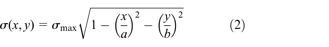
where a and b are the semi-major axis and the semi-minor axis on the contact ellipse, respectively. The maximum stress can be expressed as

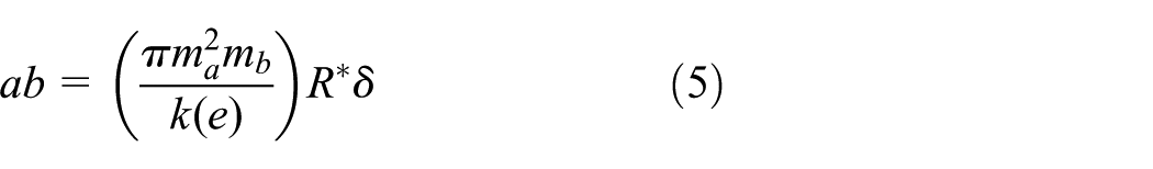
The elastic deformation loading formula can be obtained by equation (1)

where A is the coefficient of deformation, E* is the equivalent Young’s modulus, R* is the reciprocal value of the sum of the principal curvature, and ma is the coefficient of semi-major axes of contact ellipse. The contact elliptical area can be obtained
When the contact area of ball screw subjected to the normal load is to yield, the semi-major axis and the semi-minor axis of the contact ellipse are a = as and b = bs, respectively. And, σmax = σs/(1.73 * kst) is obtained based on the von Mises yield criterion, where kst is the assurance coefficient dependent on material properties. By substituting equations (4) and (5) into equation (3), the relationship between the elastic yield approach and the yield stress can be written as

Equation (6) can be rewritten as

By substituting equation (7) into equation (4), the critical yield contact force can determined as

The tangent of the equivalent elastic deformation curve at the point (Ps, δs) is the elastic–plastic deformation loading curve. Therefore, the slope of the equivalent elastic deformation curve at the point (Ps, δs) can be expressed as

Therefore, the elastic–plastic deformation loading curve equation can be obtained

The unloading curve can be expressed as

At the unloading point (Ps, δs), the contact area determined by the actual maximum normal force P and the radius of curvature Rt is the same as the contact area determined by the equivalent elastic contact force P* and the equivalent elastic contact radius R*. The elastic one R* is smaller than the equivalent plastic radius Rt due to permanent plastic deformation of the contact surfaces. Therefore, the equivalent formula can be obtained
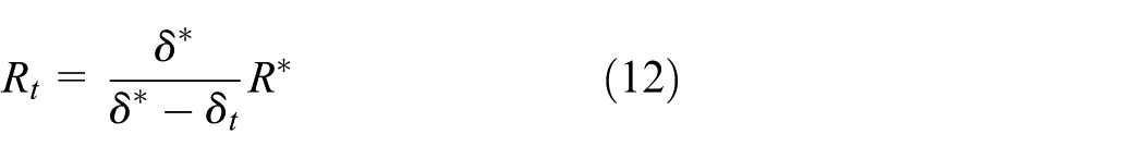
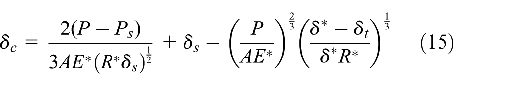
By substituting equation (12) into equations (10) and (11), the numerical solution at the intersection point (P, δ*) of the elastic–plastic deformation loading curve and the unloading curve can be obtained


By combining equations (12), (13), and (14), the equivalent plastic radius Rt can be obtained. Thus, by further deformation of formulas (13) and (14), the residual plastic deformation after unloading can be expressed as
The relationship between the elastic radius and elastic–plastic radius in the general contact case can be obtained using the Thornton theory (area equality when the maximum normal force is acting) for the equivalent elastic behavior.
The relationship between the permanent deformation of raceway, the normal force, and maximum deformation of the contact point can be obtained, which has a great importance on guiding precision prediction of ball screw under the high load. In order to verify the accuracy sustainability of ball screw under the high load, the simulation tests are implemented. The parameters used in the simulation tests are shown in Table 1, which are provided by Best Precision Company (ball screw G1604-3/P3).
Parameters used in the simulation test.

The elastic–plastic loading and unloading curves of ball screw (repeated twice) are shown in Figure 1. In addition, it is to note that the yield limit of the general loading–unloading method for ball screw is presented in Figure 1(a), and the intersection point presented in Figure 1(b) between the plastic loading and unloading curves EPL (equivalent plastic limit) can be found when a plastic deformation limit is imposed. Finally, the EHSL (elastic Hertz stress limit) can be obtained based on the elastic loading process. According to the steel deformation limit of ISO 76, δt = 0.0001db is imposed. It is possible to find the rated static load 10.7 kN that it is very close to the static load limit (G1604-3/P3, 10.8 kN). If the rated static load is computed with the elastic loading theory, the found limit for this geometry is 2% higher than the one that can be found with the elastic–plastic loading presented in Figure 1. If the first loading–unloading static load is consistent with the second loading–unloading static load, the approach of ball screw is accumulated on the former. Thus, the precision of ball screw subjected to continuous overload impact is reduced quickly.

Elastic–plastic loading and unloading curves of ball screw (repeated twice).
Figure 2 shows the elastic–plastic loading and unloading curve of screw and nut. The approach of the nut is higher than that of screw with the applied axial load. The stress–strain between ball and screw’s raceway is greater than that between ball and nut’s raceway, and the yield limit point of the nut in Figure 2(c) is greater than that of the screw in Figure 2(d), which means that the contact region between ball and screw’s raceway is more dangerous and more vulnerable to failure. Similarly, the nut’s raceway subject to rated static load in Figure 2(a) is greater than the screw’s raceway in Figure 2(b). The special craft process, such as roll compression technology of the raceway, is used to improve the yield limit of screw’s raceway and optimize the bearing capacity of ball screw.

Elastic–plastic loading and unloading curves of screw and nut.
Figure 3 shows the residual plastic deformation of the raceway versus axial load at different curvature ratios. It is obvious that the residual plastic deformation of the raceway is related to curvature ratio of ball screw. The residual plastic deformation increases with the axial load, which induces the precision loss in high-load running process. The residual plastic deformation of ball-screw contact raceway is greater than that of ball-nut contact raceway in the same curvature ratio, which verifies the yield limit of the nut is greater than that of the screw in Figure 2. In addition, the residual plastic deformation of ball-screw and ball-nut contact raceways increases with the increase in the axial load. The residual plastic deformation growth rate of ball-screw contact raceway with the increase in the curvature ratio is greater than that of ball-nut contact raceway in the same axial load. Thus, the precision loss of ball screw is mainly caused by the plastic deformation of the screw in high-load impact. When the axial load of ball screw achieves the rated capacity of 50% (axial load 15 kN, curvature ratio 1.11), the residual plastic deformation of the nut’s raceway increases nearly 2.5 times than that in rated load. One short-time larger overload can cause higher permanent plastic deformation of raceway, which induces the precision loss of ball screw in impact operational condition.

Residual plastic deformation of the raceway versus axial load at different curvature ratios.
Impact dynamic
The high-load impact of ball screw has important influence on the precision loss, which affects the positioning accuracy of the whole servo feed unit. As already demonstrated, the presented theory is functional for the evaluation of the overload impact stress limit through an EHSL with simple well-known formulas. EHSL is analyzed under equivalent, completely elastic deformation, which is bigger than EPL under elastic–plastic deformation.
It is obvious that obtaining the equivalent elastic maximum approach without considering the energy loss in overload impact of ball screw is easier than obtaining the elastic–plastic maximum approach. The result is utilizable for analyzing the maximum approach of ball screw, and it has to be described through the typical kinematical parameters of a ball screw, which is functional for the product designer.
The ball screw is subjected to overload impact during operation, which causes the elastic–plastic deformation of the contact area (contact mode for the single-nut ball screw with axial load in Figure 4). The impulse law of motion, the position of ball is changed from the free state to the overload impact contact state, can be written as

where msa is the mass of the ball; v0 and v1 are initial velocity and final velocity of the ball before and after the impact, respectively; θ is the impact angle of axial load to the nut’s axis; β is the contact angle between the ball and the raceway; α is the nominal helix angle of the screw; z is the effective numbers of the ball; and t is the impact time of the ball.

Contact mode for ball screw with axial load.
The energy conservation law of the ball based on completely elastic deformation and ignoring the energy dissipation of stress wave propagation, the screw’s mass is many times bigger than the ball’s mass, can be obtained as follows

Because of the zero approaching velocity of the ball

Figure 5 shows the equivalent elastic deformation of the raceway versus impulse at different impact angles. The equivalent elastic deformation of the raceway increases with the increase in the impulse. The equivalent elastic deformation of the screw’s raceway is higher than the equivalent elastic deformation of the nut’s raceway. The impact angle has great influence on the impact contact deformation, which decreases with the increase in the impact angle. The impact contact deformation has a relatively small change when the impact angle is over 45°. If the impact force is very close to the static load limit of the ball screw (G1604-3, 10.8 kN), the impact time of the ball according to Figure 5 is calculated (1–1.7 μs) and the impact frequency of the nut is 1000–1700 Hz. Thus, the impact contact deformation is related to the impact frequency, and high-frequency overload impact reduces the reliability of ball screw transmission.

Equivalent elastic deformation of the raceway versus impulse at different impact angles.
The precision model
The precision and the reliability of ball screw which is used in precision driving unit of aerospace industries are directly related to the bearing capacity under extreme operational conditions. The precision loss, which is affected by short-time overload impact deformation and the wear of the raceway in the long-time running, is an important index to evaluate the operation accuracy of ball screw. The wear of the raceway is not discussed in this article due to the elastic–plastic contact deformation is the main influencing factor of precision loss in short-time running.
The axial component of the elastic–plastic contact deformation between ball and raceway can be obtained

When ball screw runs within the rated load range (ci = c0, ball screw is not subjected to overload running), the precision loss of ball screw is caused by axial elastic deformation. This is consistent with Z Du’s 14 research conclusion that the precision loss of ball screw is related to elastic deformation verified by loading tests. If ball screw is subjected to a short-time overload impact in a special operation condition, the elastic–plastic deformation occurs in the nut’s raceway and screw’s raceway, and the precision loss of ball screw is induced by the accumulative residual plastic deformation under multiple overload impacts. It is obvious that different materials are used in the simulation test in Table 2 to verify the effect on the precision loss of different material properties.
Parameters of materials used in the simulation test.

The maximum stress for every couple of ball-raceway material is shown in Figure 6; in the same figure, the EHSL for every couple is reported, that is, very meaningful design parameter. From Figure 6, it is obvious that the couple of ball-raceway material (CH-CH) subjected to axial load (10 kN) is limited in the maximum stress limit. It is to say that in the same axial load, this couple of ball-raceway material is the optimum couple mode used in actual product.

Maximum stress for different couples of materials.
In Figure 7, the same results are presented in terms of residual plastic deformation for different couples of materials. The residual plastic deformation (CH-CH) is limited in the horizontal line (ci = 0.0001db is imposed in Figure 7), which has a better precision sustainability under overload impact. It concludes that different sets of material couples are used for the different industrial components. That is to say, for comparison of different couples of materials, the different actual plastic deformation limits and residual plastic deformations have to be computed through experimental tests.

Residual plastic deformation for different couples of materials.
Experiment
To verify the influence of the overload contact deformation on the transmission precision of ball screw, the loading experiments are implemented on a integrated ball screw and line guide loading test bed shown in Figure 8. The variable axial load simulated the actual working conditions that can be applied to the work table to obtain the deformation data of the raceway during the operational process.

The ball screw-line guide integrated loading test bed.
The test bed consists of control system, hydraulic loading system, and measuring system. The hydraulic cylinder is connected with the work table through the tension–-pressure sensors measuring the load. The screw is connected with the servo motor through the torque–speed sensor, which can drive the work table operating synchronously. The electro-hydraulic proportional servo valve controlling the pressure variation of the hydraulic cylinders is adjusted through the control system to simulate the actual operational process of ball screw. The encoder mounted at the end of the screw, which has a precision of 0.087° in the circumferential direction, and the linear grating ruler, which has a precision of 0.1 µm, are used to measure the contact deformation position. The travel deviation caused by the contact deformation can be obtained by the differential value between actual linear displacement and theoretical linear displacement. The actual linear displacement (the contact deformation position) is measured by grating ruler, whereas the theoretical linear displacement can be obtained by the angular displacement, which is measured by the rotary encoder multiplied by the lead. In addition, the precision loss, namely, the differential value between the initial no-loading travel variation and the loading travel variation, can be obtained by graphical method of the travel deviation according to ISO 3408-3:2006. Before the test, ball screw runs 8 h without the axial load. The contact deformation is tested first shown in Figure 9. Another operational test is implemented to measure the precision loss of ball screw shown in Figure 10. The precision loss is obtained and analyzed during the whole running life.

Position of ball screw with axial load.

Precision of ball screw with axial load.
The position relation of ball screw between axial load and deformation is shown in Figure 9. The measured results are the deformation displacements of the nut relative to the screw under the loading process. The position of the nut increases with the increase in the axial load. However, the growth rate decreases with the increase in the axial load, which is caused by the transition from elastic deformation to plastic deformation. The position is obtained and analyzed during the static test, which tallies with the theoretical values calculated under the loading process. Figure 10 shows the precision loss of ball screw with the different axial loads exceeding the rated load 10.7 kN. The measured results are the differential value between the initial no-loading travel variation and the loading travel variation obtained by reciprocating with five strokes. The precision loss of ball screw increases with the increase in the axial load. The test values are higher than the theoretical values, which is induced by the wear of raceway with the high overload. According to the ISO 3408-3:2006, V2π, V300, and Vu denote the travel variation within 2π rad, 300 mm stroke, and working stroke, respectively (V2π = 5 μm, V300 = 8 μm, Vu = 13 μm—P2 and V2π = 6 μm, V300 = 12 μm, Vu = 17 μm—P3). V2π, namely, travel variation within 2π rad, is selected as the criteria of precision loss. When the axial load of ball screw is 50% of the rated load, the precision loss of ball screw caused by the permanent plastic deformation is 1 μm and the variation of travel displacement within 2π rad exceeds the allowable variation. Thus, the precision loss of ball screw is caused by the high load and the short-time overload.
Conclusion
The high-precision precision equipments are critical for modern manufacturing industry. The precision of precision equipments is affected directly by the precision of ball screws. To improve the transmission precision of precision equipments, the transmission precision loss of ball screw subjected to overload is studied in this article. Meanwhile, a novel running bench and a precision measuring system are designed to verify the precision loss of ball screw. The theoretical calculation agrees well with the results of the experiment. The main conclusions are as follows:
The precision loss model combining the elastic–plastic contact theory is established to describe the variations in axial deformation depths.
The maximum stress and the residual plastic deformation for four couples of ball-raceway material are analyzed. The material (CH-CH) subjected to the rated static load (10 kN) is limited in the stress limit, and the residual plastic deformation is limited in the value (0.0001db). Thus, the ball-raceway material (CH-CH) has a better precision sustainability under overload impacts.
The precision loss is affected indeed by the contact deformation. The position of the nut relative to the screw and the precision loss of ball screw increase with the increase in the axial load. When the axial load of ball screw is 50% of the rated load, the precision loss caused by the permanent plastic deformation is 1 μm.
The whole precision test, which is designed and conducted based on a novel running bench to confirm the precision loss model, has been done in this article. There is very little research on the precision loss of ball screw. In addition, the results can help to provide the prediction for the precision life of ball screw operating in high-load condition.
Footnotes
Acknowledgements
The authors thank Best Precision Company for their assistance in conducting this research.
Handling Editor: Zengtao Chen
Declaration of conflicting interests
The author(s) declared no potential conflicts of interest with respect to the research, authorship, and/or publication of this article.
Funding
The author(s) disclosed receipt of the following financial support for the research, authorship, and/or publication of this article: This work was supported by the National Natural Science Foundation of China (51475267).