
Abstract
A dynamic model of the ball screw drive is proposed in this article. It is revealed that when axial thrust is transmitted between the ball screw and the nut, extra torque is generated synchronously which is not proposed in existing dynamic models. And a physical model for studying the relationship between the thrust and the torque is proposed. A lumped dynamic model is established, and a kinematic compatibility equation describing motion transmission between rotary displacement and axial displacement is established. Then a preload model of a double-nut for analyzing the force and the deformation is built. An approach to analyze the first resonant frequency of the proposed model is described. Meanwhile, a tested bench with a novel preload-adjustable double-nut and two novel loading mechanisms is constructed. The axial stiffness of the supporting bearings and the preloaded double-nut is tested based on a measurement system. Then vibration tests are carried out to measure the first resonant frequency of the ball screw drive. Finally, contrastive analysis between experimental results and simulated results of three models is conducted. The results show that the proposed model agrees much better with the experimental results than the discrete model and the hybrid model do.
Introduction
The demand for high productivity rates and high-precision parts requires faster and more accurate feed drives for machine tools.1–4 Because of high stiffness, reliable operation, ability to mitigate the impact of inertial changes, and low cost, the ball screw is the most commonly used component in feed drives to convert rotary motion to linear motion.5–7 One of the important characteristics of a ball screw drive is that its performances can be altered by exerting different preloads, such as the stiffness of the ball screw which can be improved in this manner.1,8,9 In current commercial products, preloads are almost indispensable in the ball nuts and it has general significance to study the preloaded ball screw drives.
For the ball screw drives, some performances are always used as important indexes which are always concerned by engineers and researchers, such as resonant frequencies, tracking errors, and positioning accuracy. In order to represent the characteristics as detailed as possible, dynamic models have been proposed in some researches. Feng and Pan proposed a lumped dynamic model to study the resonant frequencies and preload variation of the ball screw drive. The variation of the preload can be diagnosed by spectrum analysis of the processed experimental data and the results of the mathematical dynamic model. 10 Chen et al. developed a dynamic model of the high-speed ball screw drive system. The joint of the ball screw and the nut is equivalent to a constant linear spring in the model, and the system was formulated with Lagrange’s method. 11 Amain Kamalzadeh et al. proposed an elastic deformation model of a ball screw drive and presented a new strategy for mitigating the detrimental effect of elastic deformation using the model to offset the position command. In the model, the equivalent axial stiffness was obtained by cascading the stiffness of bearing, nut, and ball screw. 3 S Frey et al. compared the hybrid model with the discrete model in predicting the relevant eigenfrequencies of the feed system and validated the results through experiments. The stiffness of the ball nut is expressed as a linear spring in the two models. 12 Jiang and Zhu 13 analyzed the axial stiffness of the nut and supporting bearings using the Hertz contact theory of elastic mechanics and established the axial stiffness of the ball screw drive with three springs connected in series. In the above researches, the stiffness characteristics of the ball nut are always equivalent to a linear spring, therefore, the axial force is the only interactive force between the ball screw and nut. This study puts forward that the linear spring model can rarely reveal the force transmission between the ball screw and the nut accurately, and the calculation of the motion of the working table is not precise enough. An improved dynamic model is proposed in this study.
The resonant frequency is an important performance index for ball screw drives, and the system bandwidth and the anti-jamming property can be improved by increasing it. 6 In order to analyze the resonant frequency, dynamic models are commonly used. In this article, the proposed model is applied on the analysis of the first resonant frequency. Because of the nonlinearity of the model, another calculation method is adopted which is different from the one that the discrete model adopts.
This article reveals that when axial thrust is transmitted between the ball screw and the nut, extra torque is generated synchronously. And a physical model for studying the relationship between the thrust and the torque is proposed. A lumped dynamic model of the ball screw drive is established, and a kinematic compatibility equation describing the motion transmission between rotary displacement and axial displacement is constructed. Then a preload model of a double-nut is built to analyze the force and the deformation. An approach to analyze the first resonant frequency of the proposed model is described. In order to conduct experimental tests, a tested bench with a preload-adjustable double-nut mechanism and two novel loading mechanisms is constructed. The axial stiffness of the supporting bearings and the preloaded double-nut is tested. The vibration tests are carried out to measure the first resonant frequency of the ball screw drive, and the relationship between preloads and the first resonant frequency is obtained. Finally, contrastive analysis between the experimental results and the simulated results of three models is conducted. The results show that the proposed model agrees much better with the experimental results than the discrete model and hybrid model do. Therefore, this study provides an improved dynamic model of preloaded ball screw drives, and more accurate first resonant frequency can be obtained by the proposed model, which is significant for better performance of ball screw drives.
Force transmission analysis and dynamic model of the ball screw drive
A common ball screw drive is composed of a servo motor, a coupling, a ball screw, ball nuts, supporting bearings, sliders, linear guideways, a working table, and other parts.14,15 A schematic of a ball screw drive is illustrated in Figure 1. The force transmission analysis between the ball screw and the nut is analyzed in section “Force transmission analysis.” The dynamic model of the ball screw drive is presented in section “Dynamic model.”
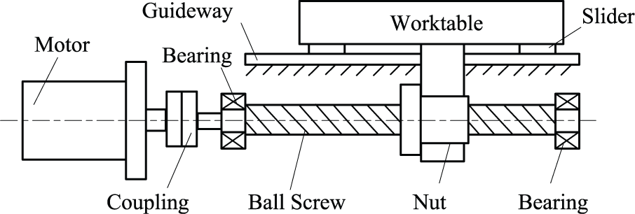
A ball screw drive.
Force transmission analysis
The interactive force between the ball screw and the nut is transmitted by rolling balls. For a two-point contact ball screw, the force analysis of a single ball is illustrated in Figure 2(a). 16 The contact force for a ball is P and can be decomposed into three component force (Figure 2(b)), axial force Fa, tangential force Fτ, and radial force Fν (Figure 2(c)). The physical equations are expressed as


where α represents the contact angle between rolling balls and grooves,
and

(a) Force analysis of a rolling ball, (b) decomposition of contact force, and (c) force projection.
Assuming that all the rolling balls are the same and there is no geometry error for the balls and the grooves, the force analysis for all the balls is shown in Figure 3. The axial thrust F is constituted by the axial component forces of all the balls, and the torque Tn is constituted by the tangential component forces of all the balls. Therefore, torque is generated synchronously when the balls transmit thrust. The working table is driven by the axial thrust, and the torque applied on the working table is balanced by the guideways. The thrust F and the torque Tn are expressed as follows


Force analysis for all the balls.
where z and R represent the number of the rolling balls and the nominal radius of the ball screw, respectively. On the basis of equation (2), the mathematic relationship between the thrust and the torque can be represented by

Dynamic model
To analyze dynamic characteristics of ball screw drives with different preloads, a lumped parameter system is modeled in Figure 4. Four degrees of freedom (DOF) are analyzed for the system, including the rotary DOF of the motor and the ball screw, the axially translational DOF of the ball screw and the working table. The interactive forces of the contact areas between the ball screw and the nut are equivalent to the thrust F and the torque Tn presented in section “Force transmission analysis.”Jm and Jb represent the inertia of the motor and the ball screw. Mb and Mt represent the mass of the ball screw and the working table. kg is the torsional stiffness of the ball screw and the coupling. ke is the equivalent axial stiffness of the ball screw and the supporting bearings. θm and θb represent the rotary displacement of the motor and the ball screw. Xb and Xt represent the axial displacement of the ball screw and the working table. Qm and Qb are the rotary damping coefficients of the motor and the ball screw; Bb and Bt represent the axial damping coefficients of the ball screw and the working table.

Dynamic model of a ball screw drive.
The dynamic equation of the ball screw drive can be described as

Kinematic compatibility equation of the working table
The relationship between forces and components motion is revealed by the dynamic model. Moreover, it is also needed to analyze kinematic transmission among the components of the ball screw drive. In the model, elastic deformation occurring in the contact areas between the ball screw and the nut is considered, and torsional deformation of the ball screw is ignored. A compatibility equation describing relationship between axial displacement and angular displacement of components is suggested. It is proposed that the displacement of the working table is composed of three parts in the equation: axial displacement Xt1 driven by rotary motion of the ball screw, axial vibration Xt2 generated by axial vibration of the ball screw, and axial deformation Xt3 caused by interactive force of the contact areas between the ball screw and the nut. Motion decomposition of the working table is presented in Figure 5. The kinematic compatibility equation of the working table can be expressed as follows

where Xt1 = u·θb/(2π), Xt2 = Xb, Xt3 = −δa; u is the lead of the ball screw; δa is the axial deformation.

Motion decomposition of the working table.
Analysis of axial contact force and deformation
There are several approaches to exert preloads, such as using oversized balls, creating offset between leads, and adjusting spacers in a double-nut.2,17 Double-nuts are commonly applied in ball screw drives and are analyzed in this study. In order to study the relationship between the axial thrust F and the axial contact deformation δa, Hertz theory is adopted, which is introduced in section “Relationship between axial contact force and deformation.” In the case of preloading, the relationship between the axial thrust and the axial contact deformation is analyzed in section “Axial deformation of double-nuts with preloads.”
Relationship between axial contact force and deformation
Hertz contact theory is a classic theory to analyze nominal contact stress and contact deformation of two elastic bodies, which satisfies the assumptions in Wang et al. 18 and Zhu et al. 19 The compression deformation of the two bodies resulting from the contact force is represented as

where K and ma are Hertz coefficients; u1 and u2 are Poisson’s ratios of the two contact bodies; E1 and E2 are elastic moduli; Σρ is the synthetic curvature at the contact point. Σρ = ρ11 + ρ12 + ρ21 + ρ22, where ρ11, ρ12, ρ21, ρ22 are principal curvatures of the contact point and can be obtained based on formulas in Wang et al. 18 and Zhu et al. 19
The Hertz contact theory describes the relationship between normal force and normal deformation along the force direction. By means of geometric projection, the axial contact deformation δa of the rolling ball can be expressed as follows
where δ1 is normal contact deformation between the ball and the ball screw, and δ2 is normal contact deformation between the ball and the nut.
The equation between axial thrust and axial contact deformation can be established as follows

where Fb is the axial thrust of a ball. The contact coefficient Kei can be expressed as follows

The axial stiffness of the nut with preload Fp is
The contact angle α is relevant with contact force. When the contact force is increased, the contact angle is increased, which results in decrease of the contact coefficient Ke. However, according to Huang and Ravani, 20 the contact angle variation result from axial load is relatively small. Therefore, the influence of contact force variation on the contact angle is ignored in the following analysis.
Axial deformation of double-nuts with preloads
Assuming that the master nut and the slave nut are the same, the axial force is the preload Fp for each nut when the working table is static and there is no external force applied on the working table. And the axial force of the two nuts is resultant force of the preload Fp and the thrust F when the working table moves. The two states are discussed as follows.
The working table is in a static state
The master nut A and the slave nut B only bear preload Fp in this state. When exerting a preload, elastic deformation occurs in the contact areas between the ball screw and rolling balls, and the contact areas between the nuts and rolling balls. The axial deformation of the nuts A and B is the same in value but opposite in direction. The axial deformation δax can be calculated as follows

The working table is in a dynamic state
When the working table moves, the axial thrust F is generated in the contact areas of the ball screw and the nut. The state in which F is smaller than Fp and the other state in which F is bigger than Fp are analyzed respectively.
Situation 1
In this situation, the preload is not less than axial thrust F. The directions of axial contact force for nuts A and B are opposite, as shown in Figure 6(a). The axial contact deformation caused by the axial thrust F for each nut is δb. The increase of the axial contact force for nut A is F1 relative to Fp, and the decrease of the axial contact force for nut B is F2 relative to Fp. The equations used to calculate the relationship between axial force and axial deformation are expressed as equation (12). In the equations, Ke is the sum of Ke1 and Ke2


Force analysis of contact areas between the ball screw and the nut in dynamic state: (a) F2 ≤ Fp and (b) F2 > Fp.
Situation 2
In this situation, the preload is less than axial thrust F. Directions of the axial contact force for nuts A and B are the same, which is different from the above state, and axial contact force of nut B is opposite to the axial thrust F, as shown in Figure 6(b). In the initial process of exerting preloads, axial contact force of the nut B decreases to zero. Then the direction of the force is reversed and it keeps increasing till the balance state. The force F2 can be obtained by the following equation. Equations (12a) and (12c) are suitable in the situation

Analysis of the first resonant frequency
The first resonant frequency is an important performance index for ball screw drives. According to equation (4), as the dynamic equations of the proposed model are intercoupling and the independent stiffness matrix cannot be obtained when the resonant frequency is calculated, the method of getting the resonant frequency by calculating the eigenvalue of the characteristic equation about the mass and stiffness matrix is not applicable. To calculate the resonant frequency, another method of inputting a pulse torque to the motor and then applying the Fourier transform to the displacement of the working table is used in this study.
As for the discrete model, the double-nut is always equivalent to a linear spring. The entire drive system is modeled using a lumped parameter system, and the dynamic equation of the modeled system can be described as equation (14), where kn is the stiffness of the double-nut, κ is equivalent friction coefficient in the direction tangential to the ball screw shaft rotation, and γ is axial displacement of the ball screw shaft caused by rotation. 10 The first resonant frequency can be obtained by calculating the eigenvalue of the equation. As for the hybrid model, it is built up in finite-element-methods using a combination of lumped mass, springs, dampers, and Timoshenko beam element, as shown in Frey et al. 12 The relationship between preloads and the first resonant frequency can be acquired by changing the double-nut stiffness for dynamic models.

Experimental setup
A tested bench is constructed to examine the relationship between preloads of the double-nut and the resonant frequency of ball screw drives, which is shown in Figure 7. The tested bench mainly consists of a master ball screw drive with a preload-adjustable double-nut mechanism and two loading ball screw drives with loading mechanisms. The front end of the master ball screw is supported by two angular contact bearings and the rear end is supported by a deep groove bearing.

The tested bench.
The preload-adjustable double-nut mechanism shown in Figure 8 consists of the following components: two ball nuts, two disc springs, an adjustment nut, a flange plate, a bending plate, a thrust bearing, and a pressure sensor (LW25150-1 klbf; product of Interface Co., USA). The preload of the double-nut can be adjusted by rotating the adjustment nut. When the adjustment nut is adjusted, the distance between the master nut and the slave nut is changed and the disc springs are compressed. Then the preload is exerted on the master nut and the slave nut. In order to restrict rotary motion of the slave nut, a flange plate and a bending plate are used to connect the mechanism with the working table. In case that the preload cannot be applied on the nuts, the axial translational freedom of the nuts is unrestricted in the process of exerting preloads. After the preload is set, the flange plate and the bending plate are fastened together by means of bolt screws, so that the preload-adjustable double-nut mechanism forms a rigid body.
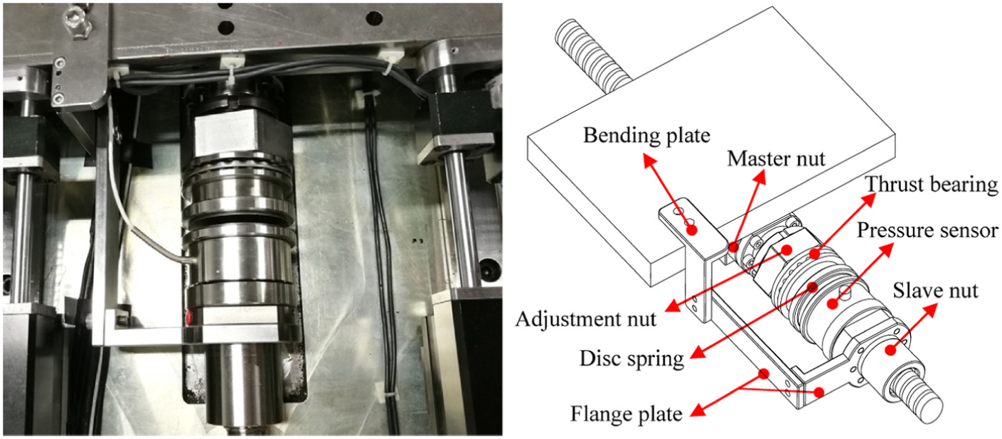
The preload-adjustable double-nut mechanism.
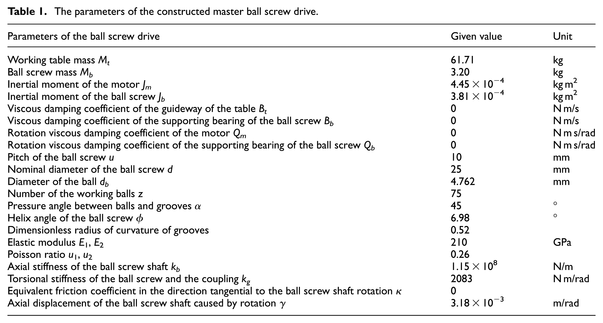
The loading mechanism which is driven by a ball screw is designed to apply axial force on the working table, as shown in Figure 9. In order to apply tension as well as pressure, two die springs are installed on both sides of the loading plate. The pressure of the springs can be controlled by adjusting position of the loading plate. A load cell (UMMA-200 kg; product of DACELL Co., Korea) is installed to test the tension and compression in real time. Two loading mechanisms are adopted and distributed symmetrically. The parameters of the constructed master ball screw drive are listed in Table 1.
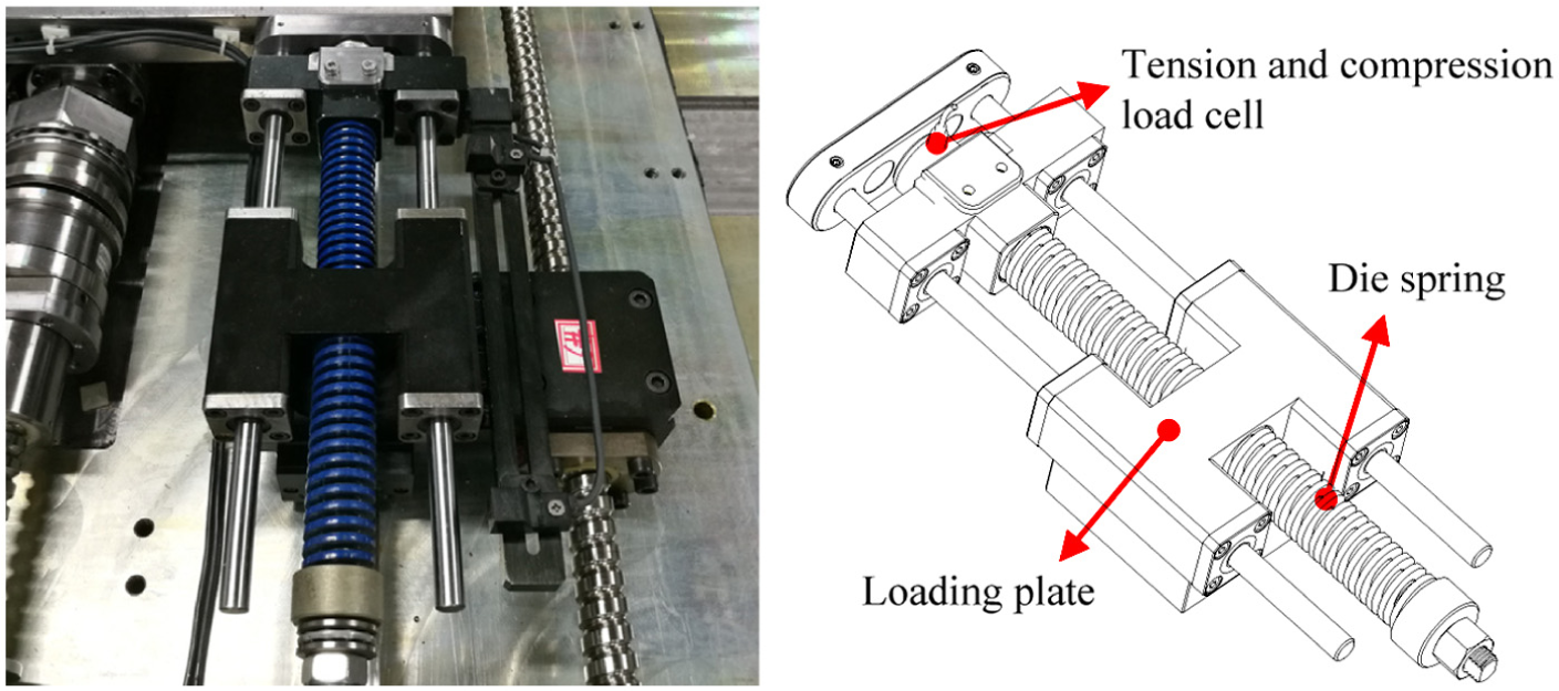
The loading mechanism.
The parameters of the constructed master ball screw drive.
Results and discussion
Tests of the ball screw drive stiffness
The stiffness of the key components has a great influence on the ball screw drive frequency; therefore, it is important to obtain accurate stiffness values. The stiffness identification experiment is conducted on the tested bench. In order to test the axial stiffness of the supporting bearings and double-nut, three laser displacement sensors are used. The first one is placed beside the front end of the ball screw to test axial displacement of the circular part which is fixed to the ball screw, as shown in Figure 10. The second one is placed at the location beside the rear end of the ball screw to test axial displacement of the ball screw end face. The third one is placed behind the working table and is used to test the axial displacement thereof, as shown in Figure 11. The value of the first sensor is the axial deformation of the supporting bearings. The difference between the second sensor and the third sensor is deformation of the double-nut.

Tests of the axial displacement of the ball screw front end.

Tests of the axial displacement of the ball screw rear end and working table.
In order to test the stiffness of the nut with preload, the approach that measures the axial deformation of the nut after applying specified axial force on the nut is always adopted. The preload should be set at first and then test the axial deformation under the action of axial load. Therefore, loading mechanisms and a preload regulating mechanism are needed, which improve the experimental requirements greatly. What is more, many experiments with different preloads need to be conducted to get more accurate relationship between preloads and axial stiffness of the double-nut. The approach that the preload can be equivalent to be the external axial load when axial stiffness is tested is taken. Therefore, the axial stiffness can be tested continuously and the experimental efficiently can be improved greatly.
In order to validate the approach, three experiments with preloads of 0, 335, and 649 N are performed, respectively. Axial load is applied by the two loading mechanisms on the working table, and range of the axial load for the three experiments is 0–900, 0–565, and 0–251 N, respectively. The constant moving velocity of the loading plates is 0.3 mm/s. Figure 12 shows the experimental results of the double-nut. The origins of the curves representing preload of 335 and 649 N are set to be 4.8 and 8.7 µm, and the abscissa is sum of preload and axial load.
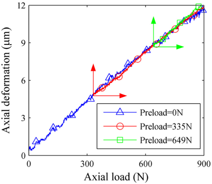
Relation between axial deformation and axial load with three preloads.
The index root mean square error (RMSE) is adopted to evaluate the difference between the curve representing preload of 0 N and other two curves. The RMSE for the curve representing preload of 335 N is 0.20 µm, and for the curve representing preload of 649 N is 0.25 µm relative to the curve representing preload of 0 N. The difference between them is relatively small and can be ignored. Therefore, the test approach of the double-nut stiffness that the preload can be equivalent to the axial load to test the deformation of the double-nut is applicative.
In order to test the axial stiffness of the supporting bearings, axial load is applied on the working table by the loading mechanisms. The range of the axial load is 0–900 N. The test results of the first laser displacement sensor and the axial load are presented in Figure 13. The axial stiffness of the supporting bearings is 9.6 × 10⁷ N/m based on the experimental result. Therefore, the equivalent axial stiffness of the ball screw and the supporting bearings is 5.2 × 10⁷ N/m. The axial stiffness of the double-nut can be obtained by testing axial deformation of the double-nut under the action of axial load. The relationship between the axial stiffness kn and the preload can be acquired by means of testing the axial stiffness of the double-nut with different preloads, as illustrated in Figure 14. It is obvious that the fluctuation of the stiffness curve is mostly caused by the measurement. In order to get rid of the effects, a fitting curve is obtained according to the experimental outcomes, as shown in Figure 14.

(a) Experimental results of three laser displacement sensors and (b) axial load applied on the working table.

The relationship between preloads and the stiffness of the double-nut.
Simulation analysis
According to Diego et al., 14 the first mode obtained by equation (14) is mainly axial, but it is also coupled with torsional vibration of the ball screw. What is more, the transmission ratio is an important parameter which has a direct influence on the degree of axial–torsional coupling. As the transmission ratio of the tested bench is 10 mm/rev which is relatively low, the discrepancy of the first mode between couple system and decoupled system is very small. 14 Therefore, the axial–torsional coupling of the first mode is ignored, and the first mode is considered to be pure axial. When the first resonant frequency is calculated by the proposed model, the discrete model, and the hybrid model, the stiffness of the double-nut is acquired from the fitting curve, as shown in Figure 14, and the region of the preload is [0 N 900 N]. In the simulation process of the proposed model, the solver ode45 is chosen to solve the differential equations and the step size is 0.0001. The simulated results of the two models are also shown in Figure 15.
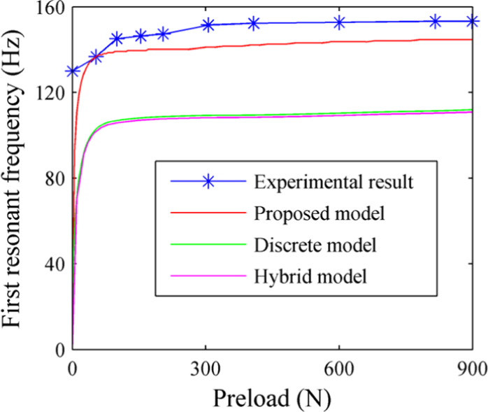
First resonant frequency comparison between simulated results and experimental results.
Vibration tests
Vibration tests are carried out to measure the resonant frequency of the ball screw drive, as shown in Figure 16. The devices used for the vibration test consist of an impact hammer, a signal amplifier, an accelerometer (356A16; product of PCB Piezotronics Co., USA), a digital analyzer INV 3018C, and data acquisition and signal processing (DASP) system. The sensitivity of the accelerometer is 103 mV/g, and an impulse hammer with a force sensor and white plastic tip is used to excited the end face of the ball screw. Acceleration signals and impact force signals are recorded by the digital analyzer INV 3018C, and frequency response functions (FRFs) are obtained with the help of the DASP system. The first resonant frequency can be acquired according to the FRFs. Vibration tests are conducted on the ball screw drive with different preloads, and the correlation between preloads and the first resonant frequency of the ball screw drive is presented in Figure 15.

Vibration tests.
It can be seen in Figure 15 that the first resonant frequency shows an increasing trend and the increasing speed slows down as the preload of the double-nut increases. The curves clearly show that the proposed model fits the experimental results better than the commonly used discrete model and hybrid model do. The percentage of the difference between the discrete model and the hybrid model is about 1%, which shows good concordance with Frey et al. 12 It is observed that at the beginning of the curve, the errors between the experimental results and the simulated results of the two models are nonnegligible. It is because that the theoretical double-nut stiffness is zero when there is no preload. However, actually even if no preload is exerted by the preload-adjustable mechanism, there are still a few preloads in the double-nut because of the machining and assembling, and they cannot be measured on the tested bench. The average of the absolute frequency errors is adopted to evaluate the difference between the simulated results and the experimental results. The relationship between the average of the absolute frequency errors and the original offset of the preload is shown in Figure 17. Simulation errors of the proposed model are less than those of the discrete model and hybrid model all the time. It is clear that the proposed model can get more accurate first resonant frequency of ball screw drives than the discrete model and hybrid model do.
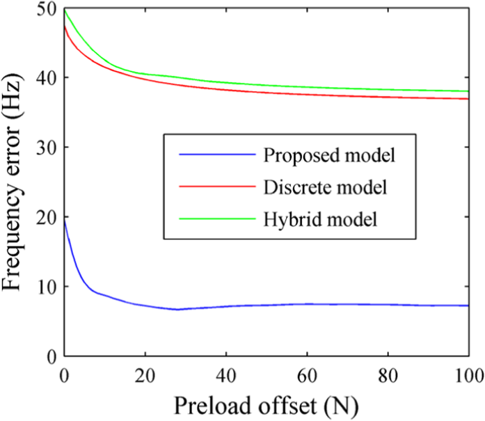
Simulated frequency errors of the three models.
Conclusion
This article has proposed a dynamic model of ball screw drives. It is revealed that when axial thrust is transmitted between the ball screw and the nut, extra torque is generated synchronously and is proportional to the thrust. Based on the dynamic model and the constructed tested bench with a novel preload-adjustable double-nut mechanism and novel loading mechanisms, the influence of preloads on the first resonant frequency is tested. And a comparison of the first resonant frequency of preloaded ball screw drives between experimental results and simulated results of the discrete model, hybrid model, and the proposed model is conducted. The results show that the proposed model agrees much better with the experimental results than the discrete model and the hybrid model do. Therefore, an improved dynamic model of ball screw drive is proposed for researchers and engineers, and it can obtain more accurate first resonant frequency of preloaded ball screw drives.
Footnotes
Academic Editor: Crinela Pislaru
Declaration of conflicting interests
The author(s) declared no potential conflicts of interest with respect to the research, authorship, and/or publication of this article.
Funding
The author(s) disclosed receipt of the following financial support for the research, authorship, and/or publication of this article: This work is supported by the National Natural Science Foundation of China (grant no. 51675292) and the National Science and Technology Major Project of China (grant no. 2015ZX04014021 and grant no. 2016ZX04004004).