
Abstract
The maximum contact strength stress in the shrink-fit camshaft assembly was obtained by finite element method. It is found that there is a maximal radial interference, below which there is no plastic deformation and which can be used as the limitation for the radial interference. In our case, the maximal radial interference is 0.08 mm. Then, based on Lamé’s equation and experimental data, the relationship between friction coefficients on the contact surface of shrink-fit camshaft and the radial interference is established. For the shrink-fit camshaft in our case, the range of friction coefficient is 0.14–0.19. After that, the relationship between the torque capacity and the radial interference for the shrink-fit camshaft is established by the finite element model for torque capacity testing based on the friction coefficient obtained before. There is a positive correlation between the radial interference and the torque capacity, but their relationship is not simple linear, similar to the exponential relationship. The slope of the torque capacity curve decreases gradually with the interference increasing. In the elastic range, the results obtained from experiment and simulation are in good agreement, with a maximum relative error of 8.1%. The results of our study are expected to design and manufacture for shrink-fit camshaft.
Introduction
Camshaft is one of the most important components in the engine valve mechanism, which determines the timing of the valve switch, which directly affects the volume of intake air, dynamic performance, and gas emission of the engine. The assembly camshaft has the advantages of light weight, low cost, compact structure, and good material matching performance. At the same time, it has the advantages of flexible manufacturing and high automation level and has become the main development direction of the camshaft manufacturing industry. 1 For assembly camshaft, because the connection strength between the cam on the steel pipe and the steel pipe directly determines the stability of the camshaft performance and the length of life, a variety of connection methods become the hotspot and keystone of the researchers. The main connection is divided into welding, powder metallurgy, expanding pipe, knurling connection shrink-fit, and so on. The first three assembly methods have the disadvantages of large deformation of camshaft and poor assembly precision, and knurling connection has the disadvantages of complicated equipment and large mounting force. 2 Shrink-fit with induction heating solves the problem of large deformation and assembly precision of the above methods. At present, a large number of research papers are focusing on welding, expanding pipe, knurling connection, and so on,3–7 and there are only few research papers focusing on shrink-fit camshaft.
Shrink-fitting is a technique in which an interference fit is realized by a relative change in size after assembly. This is usually achieved by heating or cooling one component before assembly and allowing it to return to room temperature after assembly to make a connection. The shrink-fitting method has been widely used in the assembly of mechanical parts. For the heating and cooling system, the minimum heating temperature can be determined through the relationship diagram among cooling water velocity, initial heating temperature and thermal deformation established by Xiaofeng Wang, etc. 8 For shrink-fitting, the torque capacity is the minimal torque to resist the relative rotation between the two parts assembled, which measures the assembly’s resistance to torque, and is primarily determined by the stress and friction coefficient between the contact surfaces. There are many factors that affect the torque capacity, among which the radial interference is one of the most important factors. With the increase in the radial interference, the contact stress increases obviously, the interference increases further, and the increasing rate of stress was slowed down due to the yield of the material. At the same time, the increase in the radial interference also reduces the friction coefficient, which is caused by the local yield of material, and makes small cracks between the contact surfaces, which have a negative influence on the connection strength.9–12 Obviously, the appropriate radial interference is extremely important for the torque capacity of shrink-fit connection.
Many scholars have studied the stress distribution and the torque capacity of assembly with shrink-fit, such as shaft–hub system and gear-shaft connection. By changing the axial contact length of the interference fitted shaft–hub assembly, radial interference, and other parameters, S Sen and B Aksakal 13 discussed the impact of these parameters on the contact surface stress of shaft–hub system under elastic–plastic deformation conditions. R Cao et al., 14 who studied the interference assembly of titanium–aluminum turbine shaft and K418 alloy bushings, analyzed the change of stress and the location of maximum stress during the press-fitting process. In research on mounting the gears, SJ Chu et al. 10 studied the relationship between press-fit force, radial displacement, and interference with finite element method and further obtained the range of static friction coefficient, from 0.24 to 0.4, by experimentally measuring the torque capacity. JD Booker et al. 15 proposed a theory based on Lamé’s equation to calculate the holding torque (torque capacity) of shrink-fit assemblies in which an average coefficient of friction is used. CE Truman and JD Booker 8 illustrated that the friction coefficient was related to the contact pressure in the interference assembly by the experiments designed. C Mascle et al. 16 studied the influence of many parameters on the torque capacity of shrink-fit assembly between cylinders, such as the roughness and the interference. From the above work, we can draw a conclusion that the radial interference has an important influence on the contact strength stress and friction coefficient. They vary with the radial interference, which has been proved by experiments. However, for a particular assembly, the mathematical relationship between the radial interference and the friction coefficient as well as the torque capacity is not given directly.
In this article, first, the stress on the contact surface between the cam and the steel pipe of the camshaft with the maximum interference is analyzed, and the stress on the contact surface is considered to be in the elastic state mostly. Then, based on the previous analysis, the geometric model of the camshaft was simplified, and the mathematical formula between the friction coefficient and the torque capacity was built. The values of the torque capacity of five kinds of camshaft with different radial interference were measured by experiment. Based on the mathematical formula between the friction coefficient and the torque capacity and the torque capacity from the experiment, the mathematical model of the radial interference, and the friction coefficient were established by polynomial fitting. Finally, the finite element model of the shrink-fit camshaft was established, and the relation obtained between the friction coefficient and the radial interference was applied to the model. The torque capacity was analyzed for different interference amount, and the relationship between the radial interference and torque capacity was given. This result is expected to provide reference for the design and manufacture of camshaft.
Contact stress analysis for maximum radial interference
In general, for camshaft assembled with a radial interference fit, the maximum radial interference corresponds to the maximum contact stress. However, taking into account that the heating temperature is limited and pressure-free assembly of the technical requirements is needed, the maximum radial interference is taken as 0.1 mm. In the following, the limit value of the contact stress and stress distribution of the assembly was studied.
The materials of the cam and steel pipe and their true tensile curves
In our case, the cam material is GGr15 and the steel pipe material is E355. In the interference fit of the cam and the steel pipe, the contact area may be plastically deformed because of the larger interference, which will lead to the non-linear change of the contact stress. In the following finite element modeling of assembly process, the true stress–true strain curve is needed, which can be obtained using the tensile experimental values and transferring them, as shown in Figure 1.

True stress–true strain curve.
Finite element modeling of assembly process
Description of assembly process
Assembly schematic diagram is shown in Figure 2. During assembly of the camshaft, first, the outer member, such as cams, signal wheels, and the like (in following, we use the cam to present the outer member for convenience), is electromagnetically heated and moved to position 1 by the NC assembly machine, so that the interference between the shaft pipe and the outer member is eliminated and the inner hole of the cam is larger than the outer surface of the steel pipe. Second, the outer member is moved, by the manipulator of the numerical control assembly machine, accurately from the position 1 to the preinstalled position 2 on the steel pipe, without press-fit force due to no interference. Then, the cam which is just assembled in position 2 is forced to cool by a cold air in high speed, and the cam shrinks to accurately and quickly fix to the steel pipe at position 2. With the above method, the cam, oil pump cam, signal wheel, and so on, are assembled in sequence according to the specific order.
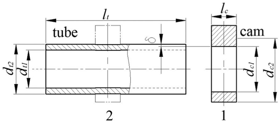
Assembly schematic diagram of camshaft.
In Figure 2, let dt1, dt2, and lt be the inner diameter, outer diameter, and length of the steel pipe, respectively. Before the shrink-fitting, the inner diameter of cam dc1 is obviously less than dt2. dc2 and lc, respectively, represent the diameter of the cam base circle and the width of the cam. Let
Geometric and physical parameters
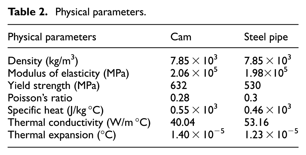
When there is a large radial interference, the plastic deformation of the contact area will occur. In the simulation of assembly process, the maximal between the cam and steel pipe is taken as 0.1 mm. Tables 1 and 2 show the geometrical dimensions of the cam and the steel pipe and the associated physical parameters. 17 The relationship between true stress and strain is shown in Figure 1.
Geometric dimensions.

Physical parameters.
Simplification and meshing of three-dimensional models
In the assembly process, there are a few cams to fit onto the steel in order, in which each fitting process is independent, so that in the modeling process, only one cam is taken into consideration in the article. For simplicity of the model, the small fillet machined in order to guide the assembly is neglected. There is always a heat exchange among the cam and the steel pipe and the environment during assembling. In the process of modeling, the complex process of mechanical gripper grasping parts to assembly is simplified, and the heating temperature is set near the actual assembly temperature.
Simulation belongs to the coupled temperature–displacement analysis; the element type is C3D8T with thermal freedom. The contact area between the steel pipe and the cam is the focus of study. Therefore, the mesh in this area should be refined to obtain more accurate results. As for the finite element model that with 0.1mm interference, the total number of elements for the cam and the steel pipe are 9756 and 3600. As for the finite element model that with 0.1mm interference, the total number of elements for the cam and the steel pipe are 9756 and 3600.
Interaction and boundary conditions
Simulation mainly involves two types of a total of four kinds of interaction situations; one is the mechanical interaction property, and it is set as penalty function and hard contact. Another type of thermal contact properties has three contact situations: first is the natural convection of the outer surface of the assembly and the air throughout the assembly process, the second is the convection between the contact surface and the forced cold air flow in the forced cooling stage, and the third is the heat transfer between the steel pipe and the cam, and the heat transfer coefficients are nonlinear functions of cooling water flow rates. 18 The heat transfer coefficient in contact surface between the steel pipe and the cam continuously varies with the contact pressure and is given by the paper by Graff. 19
Boundary conditions can be divided into two categories: thermal boundary and mechanical displacement boundary. During the heating stage, the cam is set to a temperature boundary condition that the cam is expanded to eliminate the interference. During assembly, end of the steel pipe is fixed, and an appropriate axial displacement is applied to the cam toward the steel pipe, which moves the cam fit to position 2. The final finite element model is shown in Figure 3.
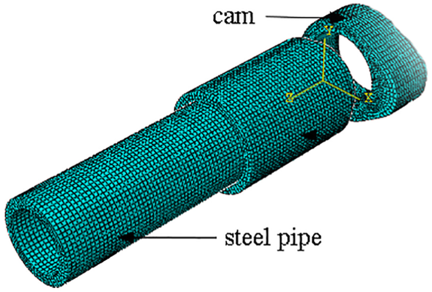
Finite element model of camshaft.
Contact strength stress analysis
Figure 4(a) shows the contact strength stress described by von Mises stress nephogram on the contact surface of the cam inner hole and the steel pipe when the radial interference is 0.1 mm. The results show that the stress is distributed symmetrically on both sides of the geometric symmetry plane β of the cam, and the closer to the cam end in axial direction, the greater the stress is. The area of stress concentration appears on the edge of the intersection of cam end and the inner hole of the cam. The maximum stress is 719 MPa, which exceeds the yield limit of cam material, indicating that plastic deformation occurs in some areas. Figure 4(b) shows the equivalent plastic strain nephogram of the inner hole of the cam. The results show that plastic strain still distributes symmetrically along the plane of
Figure 4(c) and (d) shows the Mises stress and the equivalent plastic strain nephogram of the steel pipe. Compared with the cam, the maximum stress of the steel pipe is 575 MPa, which appears at the inner hole of the steel pipe, not on the contact surface. The maximum stress on the contact surface of the steel pipe is 560 MPa, which corresponds to the position of the maximum stress of the cam. The maximum stress on the contact surface of the steel pipe is larger than the yield strength of the tube material, and there is a little plastic deformation on the contact surface. The maximum amount of plastic strain produced on the inner surface of the steel pipe is 0.000264.

The results of finite element analysis: (a) von Mises stress of the cam (MPa), (b) equivalent plastic strain of the cam (MPa), (c) von Mises stress of the tube (MPa), and (d) equivalent plastic strain of the tube (MPa).
The above analysis shows that for the maximal interference 0.1 mm, the region of plastic deformation is relatively small. The number of elements of plastic deformation on the contact surface account for only 4.1% of the total number of elements, so the plastic deformation has little influence on the mechanical properties of the model. In general, the greater the interference, the greater the contact strength stress. Therefore, for the interference below 0.1 mm, the contact strength stress of the camshafts is considered to be within the elastic limits of the two materials. Plastic deformation can be neglected when establishing the theoretical model.
Mathematical model of friction coefficient
In this section, according to the research works by Truman and Booker and Chu,9,10 the friction coefficient will change with the change in contact pressure. The mathematical model between friction coefficient and radial interference is established by theoretical deduction and experiment. The conclusion will be further applied to the simulation of camshaft in the following work.
The mathematical formula of the relationship between friction coefficient and torque capacity
Simplification of geometric model and stress distribution of shrink-fit camshaft
For a well-assembled shrink-fit camshaft, the stress distribution on the contact surface is assumed to be symmetrical. The outer contour of the cam has a negligible effect on the pressure on the contact surface. Thus, the camshaft model is simplified as interference fit for two thick-walled circular cylinders. The stress change in the axial direction of the contact surface is negligible relative to the radial and circumferential stresses, and the pressure, in the axial direction, between the contact surfaces is considered to be uniform in the axial direction. The simplified geometric model of shrink-fit camshaft is shown in Figure 5.

Thick-walled cylinder model.
Mathematical formula of torque capacity and friction coefficient
According to the above simulation of contact strength stress, when the radial interference is 0.1 mm, the plastic deformation area in the contact area accounts for only 4.1% of the whole contact area. The mathematical model can be treated as elastic deformation. For the simplified model, the following work is based on Vullo. 20 The normal assembly pressure pf determined by the radial interference is given by equation (1)

where δ is the radial interference, the coefficient re is the radius of the joint surface experimentally determined, the coefficient k is given by equation (2)

In equation (2), Ec and Et are Young’s moduli of cam and steel pipe materials; νc and νt, respectively, are their Poisson’s ratio; ra, rd, and re, respectively, are the outer radius of base circle of the cam, the inner radius of the steel pipe, and the outer radius of the steel pipe. Thus, when the radial interference is given, the normal assembly pressure pf has been determined by equations (1) and (2).
If l is the length of the contact surface in the axial direction, the relation between the resultant moment Mf (referring to torque capacity here) and the friction coefficient u is equation (3)

Torque capacity experiment
The relationship between the friction coefficient and the torque capacity of the camshaft was given, and the key geometric parameters of the assembled camshaft were obtained by measuring the torque capacity—torque capacity test was carried out for the camshaft with different radial interference. After obtaining the torque capacity of camshaft, the relationship between the friction coefficient and the radial interference was deduced by equations (1)–(3). This relationship will be applied in the finite element model.
Experimental method
According to the magnitude of radial interference, the experiment was divided into five groups. Each group has eight cams on the steel pipe and one steel pipe, in which the radial interference of the camshaft is constant. The outer diameter of the steel pipe is unchanged, and the different interference were controlled through the different cam inner holes. The radial interference is 0.02, 0.025, 0.035, and 0.05 mm, respectively. After the torque capacity test, eight values of torque capacity were obtained under the same radial interference. Figure 6(b) shows the five groups of complete shrink-fit camshafts. In the each group, eight cams were numbered from left to right. Figure 6(a) and (c) shows CNC assembly machine and torque capacity testing machine, respectively.

Experimental equipment and shrink-fit camshafts tested: (a) CNC assembly machine, (b) camshaft, and (C) torque capacity testing machine.
Experimental results of torque capacity
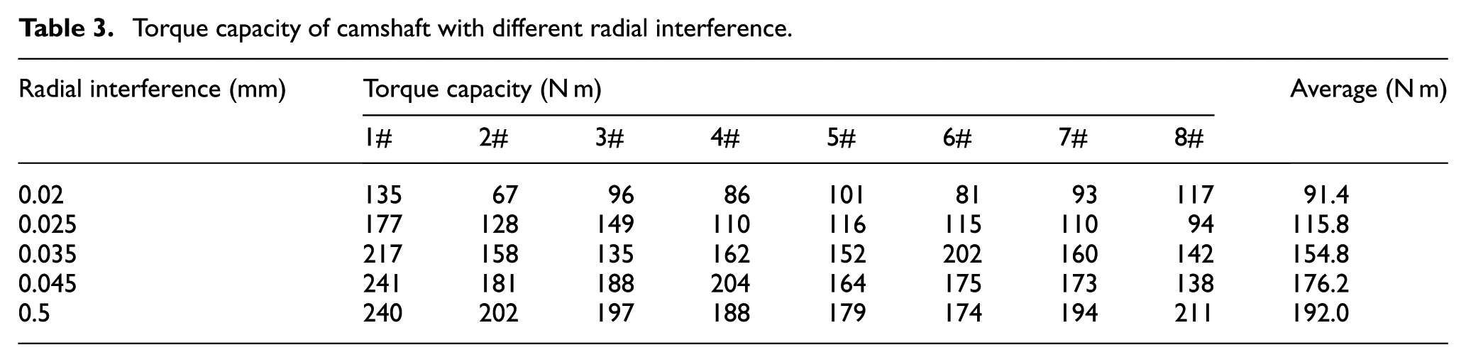
Table 3 shows torque capacities of the shrink-fit camshafts under different radial interference.
Torque capacity of camshaft with different radial interference.
Calculation of friction coefficient
As shown in Figure 7, at the installation position of 1# cam, the diameter of the joint surface of the nosepiece and the steel pipe is dn, the axial mating dimension is ln, dn > dt1, and the nosepiece and the steel pipe are also assembled in interference fit. The fitting area of steel pipe and the nosepiece and that of the cam and the steel pipe coincides in the axial direction. Nosepiece without holes is a solid shaft. After the nosepiece is installed, the steel pipe is expanded in the radial direction to make its diameters increased to dt3 and dt3 > dt2. Therefore, the actual interference between the 1# cam and the steel pipe is increased, and torque capacity increased. Considering the above reasons, the torque value of the 1# cam in the experiment should be ignored. In statistics, the maximum and minimal values of the torque capacity should be negligible. Mt is the average torque capacity calculated through such a method, which represents the torque capacity obtained by experiment, which is used to replace the Mf in Equation 3 and to calculate u in Table 4.

Assembly schematic diagram with nosepiece, cam, and steel pipe.
Friction coefficient and other relative parameters calculated (i -radial interference).

The coefficient k corresponding to the different radial interference is calculated according to equation (2), the normal contact pressure pf is determined by equation (1), and finally the value of friction coefficient u corresponding to different radial interference is determined by equation (3). Table 3 shows the torque capacities obtained by testing. Table 4 shows the friction coefficient and other relative parameters calculated by equations (1)–(3).
The polynomial interpolation is carried out with the radial interference as the independent variable and the friction coefficient as the dependent variable, and the mathematical relationship between the radial interference and the friction coefficient is obtained. Using the Lagrange interpolation polynomial, the interpolation function is as follows

where li is given by

When n = 3, the expression is simplified as shown in equation (6)

Draw the fit curve of the radial interference and the friction coefficient, as shown in Figure 8.

The relation curve of the radial interference and the friction coefficient.
As can be seen from Figure 8, in general, the relationship between the radial interference and the friction coefficient is that the friction coefficient decreases with the increase in the radial interference. Among the radial interference 0.020–0.025 mm, the friction coefficient has a slight increasing trend, while among the radial interference 0.025–0.050 mm, the friction coefficient has a decreasing trend. According to the existing friction theory, the reason for this phenomenon is that the contact pressure is too large and over the yield limit of material, which produces the “flattening effect.”
Finite element model of torque capacity
Finite element model
A description of the problem for torque capacity testing
In the torque capacity testing, the steel pipe is fixed and the torque is applied to the cam and gradually increased until the relative motion occurs between the cam and the steel pipe and they slip relatively and the torque applied keeps almost unchanged. As shown in Figure 9, position 1 shows the previous state of the cam in the solid line, and position 2 shows the slipping state of the cam in the dashed line.

Schematic diagram of the torque capacity testing process of a cam.
Interaction and boundary condition
In the torque capacity finite element model, it is necessary to establish a reference point at the center of the cam assembled, which is coupled to the outer surface of the cam. The reason why the coupling constraint is added on the outer surface is that the clamp fixes the steel pipe and the outer surface of cam is loaded in the torque capacity test of camshaft. The interaction between the cam and the steel pipe is mechanical interaction property, described as penalty function and hard contact. After the assembly simulation is completed, the final state of the stress field of the camshaft needs to be read and taken as the original state for torque capacity testing model. Then the torsional boundary condition is set up. As the reference point is coupled to the outer surface of the cam, the angular displacement is applied to the reference point.
The effect of the radial interference on the torque capacity
The connection strength of the shrink-fit camshaft depends on the contact pressure between the cam and the steel pipe and the friction coefficient. The ability of the camshaft to withstand the torque reflects the strength of the camshaft connections. Using the relation between the friction coefficient and the interference given by equation (6), the friction coefficient is obtained. The simulation for the torque capacity testing is carried out, with different radial interference values, 0.02, 0.025, 0.03, 0.035, 0.04, 0.045, 0.05, 0.06, 0.07, 0.08, 0.09, and 0.1 mm. Figure 10 reflects the relationship between the rotation angle and the torque capacity for different amounts of interference.

Curves of rotation angle and torque capacity for different radial interference.
In Figure 10, the straight line is set to perpendicular to the x-axis at the 0.0059 rad, which is twist angle between the cam and the steel pipe to show the connection failure. The values at y-axis of the intersection points between the straight line c and the curves of rotation angle and torque capacity are ones of the torque capacity for difference radial interference. Before the torque increases to the torque capacity, the cam and the steel pipe only have an elastic deformation and do not slip. As the torque increases to torque capacity, the cam begins to slip. Until the slip to a given boundary condition of 0.052 rad, the assembly connection is considered as failure. In the event of elastic deformation, the torque capacity and the radial interference are positively correlative, close to the proportional relationship, that is, the torque capacity increases with the increase in the radial interference. The torque capacity is 79.2 N m for interference 0.015 mm, 272.3 N m for 0.08 mm. Figure 11 shows that von Mises stress of the assembly connection for radial interference 0.08 mm is 664 MPa, which is greater than yield limit of the cam material. When continuously increasing the interference, the cam and the steel pipe will undergo plastic deformation, and the plastic deformation will not only reduce the connection stress but also produce a certain deformation. When the interference is too large, the cam, even with high strength, high wear resistance, and lower plasticity, will be broken. Therefore, large interference between cam and steel pipe shall be avoided.

Von Mises stress of the cam and the steel pipe due to radial interference 0.08 mm (MPa).
For different types of camshaft bearing different torque, in order to ensure certain connection strength between the cam and the steel pipe, the radial interference is as large as possible until leading to the plastic deformation in the simulation for the shrink-fit.
Furthermore, the values for different interference below 0.08 mm are used to interpolate. The radial interference is taken as the independent variable and the torque capacity as the dependent variable. After trying various fitting methods, it is found that the exponential model for interpolation is the best in statistics, with a variance (SSE) of 15 and the coefficient of determination (R2) of 1, expressed as equation (7). The interpolation curve for the relationship between the torque capacity and radial interference is shown in Figure 12


Comparison of experimental and simulated torque capacity.
In general, there is a positive correlation between the radial interference and the torque capacity, but their relationship is not simple linear, similar to the exponential relationship. The slope of the torque capacity curve decreases gradually with the interference increasing.
Comparative analysis between experiment and simulation
The experimental results are compared with the simulation results, as shown in Figure 12. The graph is divided into two parts: the curve with an asterisk is drawn from the simulation data for the radial interference from 0.15 to 0.1 mm and the curve with the diamond from the experimental data from 0.02 to 0.05 mm. From the results, the experimental data and the simulation data are in good agreement, their maximum error occurs when the radial interference is 0.05 mm, and their relative error is 8.1%, which proved that the finite element modeling of shrink-fit assembly process and the torque capacity testing are effective and practical.
Conclusion
Based on the experimental and finite element analysis, the relationship between the torque capacity and the radial interference for the shrink-fit camshaft is established. There is a positive correlation between the radial interference and the torque capacity, but their relationship is not simple linear, similar to the exponential relationship. The slope of the torque capacity curve decreases gradually with the interference increasing. In the elastic range, the results obtained from experiment and simulation are in good agreement, with a maximum relative error of 8.1%. In addition, the relationship model of the radial interference and the friction coefficient is obtained by the experiment and the polynomial interpolation.
The friction coefficient between the contact surfaces of the cam and steel pipe is related to the radial interference. As the radial interference increases, the friction coefficient decreases in general. For the shrink-fit camshaft in our case, the range of friction coefficient is 0.14–0.19.
There is a positive correlation between the radial interference and the torque capacity when there is no larger plastic deformation of the cam or the steel pipe. In order to avoid the plastic deformation on the assembly surface of shrink-fit camshaft, the radial interference cannot be greater than a certain value. In this article, the interference between the cam and the steel pipe did not exceed 0.08 mm.
Footnotes
Handling Editor: Jianjun Zhang
Declaration of conflicting interests
The author(s) declared no potential conflicts of interest with respect to the research, authorship, and/or publication of this article.
Funding
The author(s) received no financial support for the research, authorship, and/or publication of this article.