
Abstract
The article reviews the technical solution applied to these machines which are currently in use worldwide. Special attention is paid to the new concept of a cutter drum powertrain system, where the permanent magnet technology motors are proposed. Placing them inside the cutting drum results in improved dynamic performance of the mining process, as well as the possibility of modular configuration depending on the required operating condition. The authors analysed the dynamics of mining in continuous miner machines, where the adverse impact of vibrations during this process was noticed. The reason for this problem is the occurrence of resonance frequencies in the structure of the machine, which significantly shortens its life time. In previous publications, approaches based on avoiding resonance and adjusted shape modes to reduce displacement of cutter drum were presented. One of the ways to achieve this effect is to control cutter drum’s angular velocity. It allows thinking about a new concept of vibration-control system based on smooth speed change of the cutter drum or/and the angular speed of the boom.
Introduction
Coal is still a key energy source for many countries. An increasing share of coal beds is represented by thin layers with a thickness less than 1.2 m and remnants of seams which require work on a board and pillar system. The core machines designed for this purpose must have high productivity with limited geometrical dimensions. In general, these types of roadheaders are called ‘continuous miners’. The geometrical restrictions, in this case, are strongly correlated with the design form of the machines.
Continuous miners are mining machines equipped with a milling head with dimensions corresponding usually to the width of the heading or the tunnel. The milling head is usually installed on a boom, which most often performs a simple swinging motion in a vertical plane. The face is mined at the entire width of the heading. Where it is necessary to widen the heading, the miner is moved to a new position, or the cutting assembly alone is rotated in a horizontal plane to mine the subsequent beds or layers of rocks. Continuous miners are often used for the exploitation of coal and other useful minerals using room and pillar mining systems. (Prof Adam Klich and Dr Krzysztof Kotwica). 1 Continuous miners, manufactured by companies such as Joy, Jeffrey, Sandvik, Eickhoff and Caterpillar, are used as a standard solution mostly in the American and Australian mining. Boom-type continuous miners are different to other roadheaders in terms of the method used to mill the face of the heading and thus a different milling head solution – in the form of a cylinder or a drum. Due to the vertical movement of the head from top to bottom, the application of a turn table in such types of roadheaders is usually not necessary. The continuous miners move on a heavy-tracked chassis with a loading table in the front, where the mined material is scraped towards a scraper conveyor located in the central part of the continuous miner. The scraper conveyor is equipped with an extension facilitating the transfer of the mined material to another means of haulage. A flat, extensible or non-extensible telescopic boom is mounted to the front part of the tracked chassis, at the end of which, the cylinder or drum milling head is attached. The milling head is capable of changing its width slightly by means of telescopic extensible side parts of the head.
Depending on the structure of the boom, the main movement, until the full slotting of the head is reached, is conducted by means of the tracked chassis or by the extensible boom itself.
Continuous miners are equipped with a milling head of a size corresponding to the width of the heading or tunnel. The head is installed on the boom that usually performs a simple swinging motion in a vertical plane. The heading face is mined at the entire width of the heading. Where it is necessary to widen the heading, the miner is moved to a new location, or the cutting assembly alone is rotated in a horizontal plane to mine the subsequent beds or layers of rocks.
The standard solution among continuous-mining headers includes the continuous miner and bolter miner machines. These machines have numerous applications, including American and Australian mining industries, for extracting deposits of hard coal, salt, potassium or gypsum, as well as for preparatory works and tunnel drilling in stone.2–5
The majority of continuous miner and bolter miner machines can be used in mining and geological conditions where it is possible to apply roof bolting. Due to significant costs and amount of required labour in the execution of a heading, steel arch support sets are very rarely applied. 6
The first constructions of this type, as well as patent claims, emerged at the turn of the 19th and 20th centuries. An example is a construction proposed by F Pawel 7 in a patent application dated 11 September 1902 (Figure 1).

One of the first patents of continuous miner machines: ‘Apparatus for performing earthworks’– patent US 720841. 7
Currently, almost all of the world’s major mining machinery manufacturers offer this type of header. Examples include the machines constructed by Joy Mining Machinery, Sandvik Mining Construction, Caterpillar Inc and Eickhoff GmbH, as presented in Figure 2.8–11

On the basis of a literature review and technical specifications of existing machines, design assumptions were defined. Based on these data, a geometric and mathematical model of the analysed machine was developed. Among many aspects were modal analysis and sensitivity analysis with selection of dynamic features.
As final result of research was presented, the concept of vibration-reduction control system was dedicated for continuous miner machines.
Analysis of continuous miner development trends
Trends in the development of continuous miner machines result from the requirements set by customers in global markets and the strong competition in the mining machinery sector. A total of 41 headers by different manufacturers were analysed for reflecting those trends. The data of the latest design solutions were obtained from official databases available on websites.8–11
The analysis involved juxtaposition and statistical comparison of the key parameters such as the geometric and kinematic parameters of the cutting process, as well as the energy parameters related to the power of the motors installed. The geometric parameters taken into consideration refer to the minimum and the maximum cutting height, to the width and the diameter of the cutting head, as well as to the total mass of the machine. The energy parameters, on the other hand, refer both to the total power of the motors installed in the header and the power of the motors in the cutting assembly. Figure 3 presents the summary of sample geometric parameters of the cutting process of all the machine constructions under analysis.

Summary of continuous miners geometrical parameters.
As can be observed in this diagram, the minimum cutting height is closely linked to the geometry of the cutting head. This can be seen by analysing the graph in Figure 4(a), where the line of the trend clearly indicates an increase in the diameter of the cutting head depending on the maximum and the minimum cutting height. At the same time, the maximum cutting height results from the design form of the boom. In all the cases analysed, the cutting width is an independent parameter in relation to the kinematics of the boom and ranges between 2900 and 4115 mm, which has been presented in Figure 4(b).

Trends between: (a) cutter drum diameter versus cutting height and (b) cutting width versus height.
The summary of energy parameters for the headers analysed can be observed in Figure 5. The diagram shows that there is a correlation between the mass of the headers analysed and the power of the motors used.

Summary of continuous miners energy parameters.
The abovementioned dependence has been analysed in the diagram presented in Figure 6(a). The statistical analysis conducted by means of linear approximation indicated that the power density coefficient for the analysed headers is on average equal to 0.12 kW/tonne, whereas the coefficient determining the total power of the installed motors to the power of the cutting head’s drive motors amounts to 0.64, as illustrated in Figure 6(b).

Trends between: (a) total power versus total power and (b) total power versus cutter drum power.
Figure 7(a) presents the dependence between the angular velocity of the cutting head and the power of the motors used to drive the head. It is possible to discern a characteristic trend related to the need to generate a constant drive torque necessary to mine the rocks in the case of all the machines under analysis. Taking into account the slope factor of the trend line, one can determine the average value of the drive torque, which is equal to 34377 Nm for the cases analysed.

Trends between: (a) cutter drum speed versus cutter drum power and (b) cutter drum power versus cutting height.
The diagram presented in Figure 7(b) shows the correlation of the power values of the cutting head motors to the minimum and the maximum cutting heights. The analysis of the data presented permits to state that the influence of the cutting height on the power demand is insignificant. This can be confirmed by the high dispersion of the points in relation to the trend line expressed by the square of the correlation coefficient equal to 31% for the maximum cutting height and 34% for the minimum cutting height.
Review of continuous miner cutter drum powertrain systems trends
As a result of the patent analysis in the global bases United States Patent and Trademark Office (USPT), World Intellectual Property Organization (WIPO), Japan patent office (JP), European patent office (EPO) German patent and trade mark office (DPMA) limited to a specific ICP classification (E21–FIXED CONSTRUCTIONS–EARTH DRILLING; MINING), as well as using the key word ‘continuous miner’, it was concluded that there is currently a strong, growing trend for new design solutions in continuous miner machines. This has been illustrated in Figure 8, in which a record number of 64 patents was reached in 2014.

The above summary includes patents concerning various design aspects of this type of header. In view of a large number of patents (1024 publications) and their diversity, it was decided that discussion would encompass patents in the field of cutting head drive transmission, particularly by means of electric motors located inside the cutting head body. For this reason, the search field was limited using the presence of key words ‘drum’ and ‘driver’ in the abstracts of the patent publications, which helped to reduce the number of available patents to 25 items. However, by searching the cited patent publications in this group of patents, it was possible to select additional solutions which did not use the key word ‘continuous miner’.
Table 1 presents a chronological summary of the patent solutions in the field of drive transmission. They refer both to the manner of locating the drive motors and to the design solutions for the cutting head drive transmission.

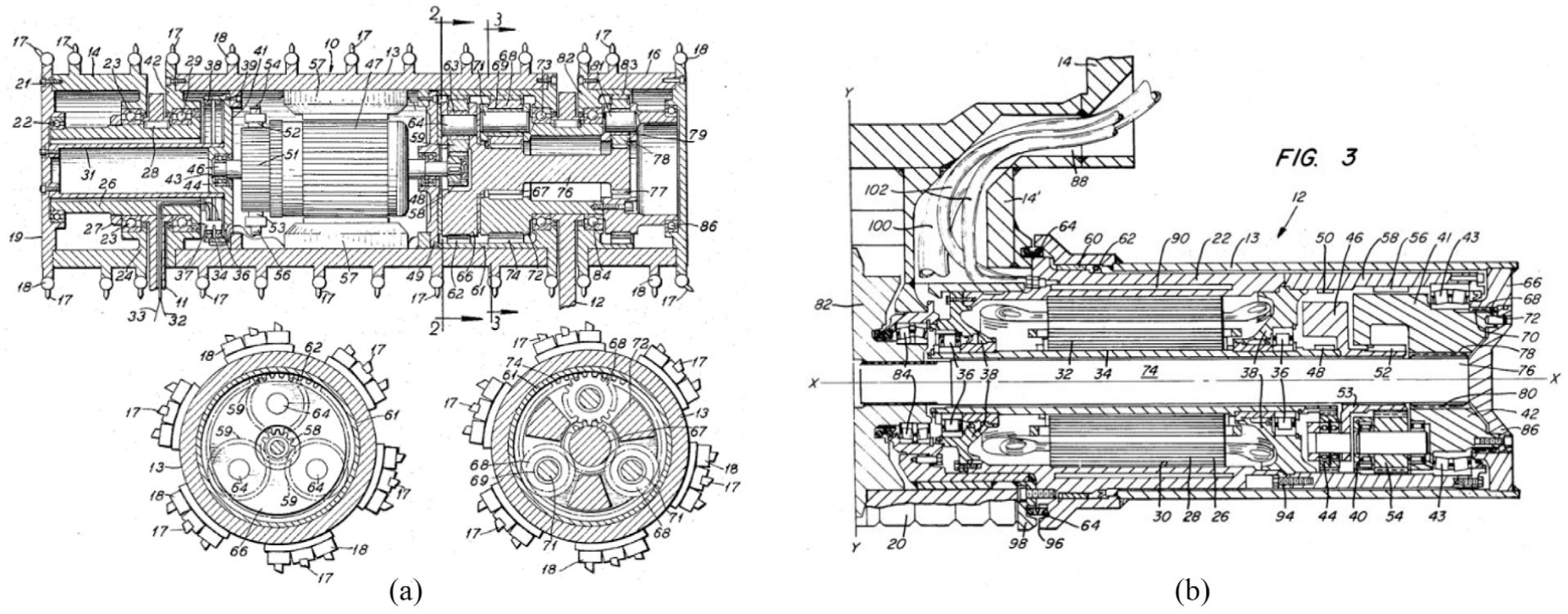
As can be seen, as early as the 1960s and 1970s, the constructors saw advantages in the introduction of electric motors into the cutting head body. However, the technology available at that time did not allow for obtaining sufficient power density which would make it possible to operate these machines under heavy load conditions. The solutions from that period are illustrated in Figure 9(a) and (b).
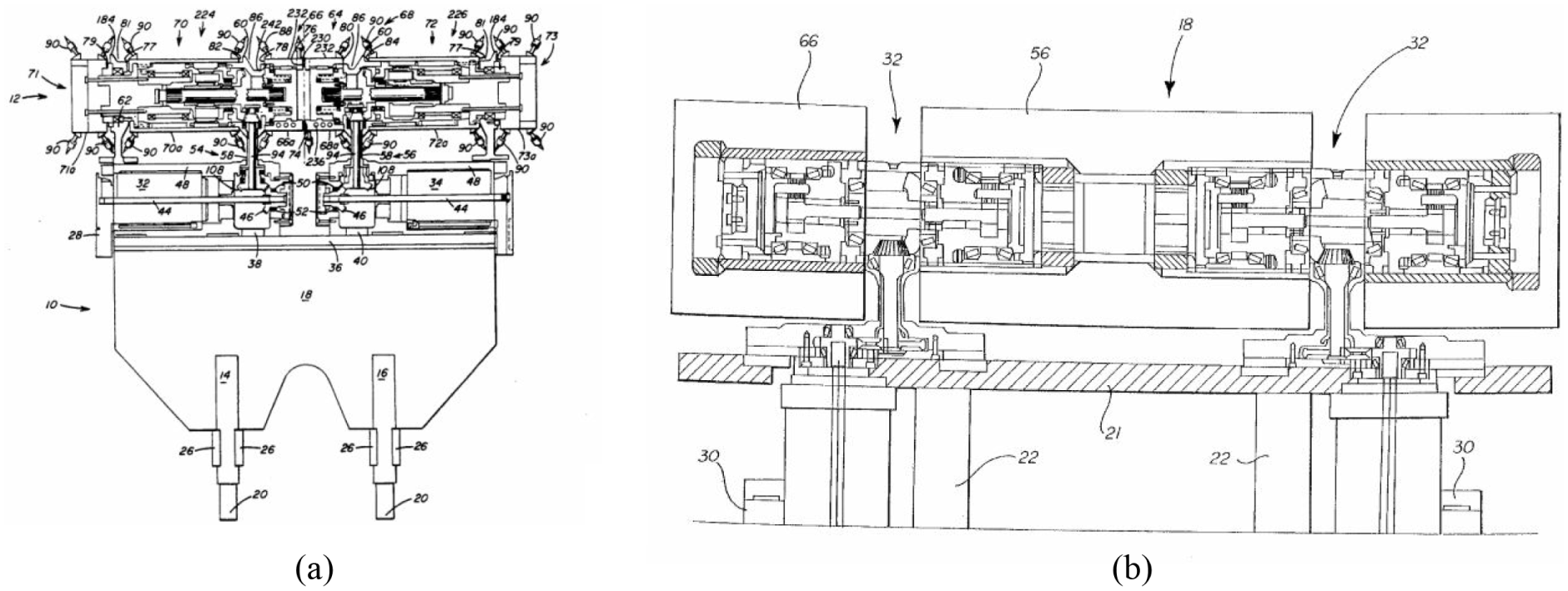
It was not until the 1990s that successive solutions emerged in this field. The impossibility of obtaining a suitable power density of electric motors was compensated for by placing them on the boom close to the cutting drum (Figure 10(a) and (b)). Such a solution had a series of advantages compared with the systems where the motors were placed on the chassis of the header.
The rapid development of electric motors today, particularly in the permanent magnet technology, makes it possible to obtain high power density, which paves the way for returning to the concept of placing them inside the cutting drum. In literature,18–22 many applications of this technology in working machines can be found. This also may be exemplified by the patent presented in Figure 11, where the constructors have integrated the motor with the gear on the external sections of the cutting drum.

Powertrain of cutter drum: ‘A cutter head containing its motors and gearcase’ patent US 8235470. 23
New concept of vibration-reduction system for continuous miner
Taking into consideration the abovementioned state of the art, we propose a modular structure of the cutting drum with integrated permanent magnet synchronous machine (PMSM) motors (Figure 12). The performed numerical calculations indicate that the value of the torque generated by the permanent magnet motors combined with a double-reduction planetary gearbox is sufficient and is presented in the Table 2.
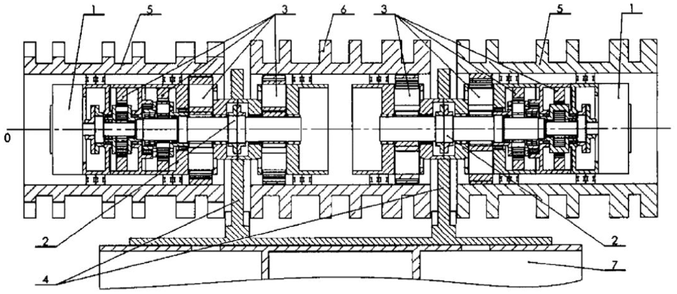
The modular drive of the cutting head of a continuous miner. Patent PL 224 770 B1. 24
Data of prototype PMS motor and moments of inertia of continuous miner model presented in the Figure 13.

PMSM: permanent magnet synchronous motor.
The modular drive of the cutting drum (Figure 12), according to the solution by the authors of the paper, is characterised by the fact that the drive system consisting of planetary gearboxes (3), couplings (2) and drive units (1) arranged along the axis of rotation, inside the body of the cutting drums (5, 6), constitutes a single, modular drive transmission system of the cutting drum. The modular drive is connected to the boom body (7) and the load-bearing supports (4). The drive torque of the modular drive system is transmitted to the lateral cutting heads (5) and the central cutting head (6) through the large wheels of the planetary gearbox (3).
The application of a modular drive system allows for its placement along the axis of rotation, inside the cutting heads, thus avoiding the necessity to transmit the drive torque along the boom body of the continuous miner. The application of such a solution in a continuous miner allows for the development of the cutting head by adding consecutive modules increasing the power of the drive and the width of cutting. This solution allows for decreasing the cross-section of the cutting heads supports, thus resulting in a decrease of a passive area in the cutting head. Eliminating components of the drive transmission system along the boom body allows for the increase in the rigidity of the cutting drum supports and improves the dynamic performance of the boom by reducing vibration influence. 25 This solution was applied in new design continuous miner concept machine (Figure 13).

Visualisation of continuous miner machine with integrated PMSM motors inside cutting drum (length dimensions in mm).
The idea of the new concept of vibration-reduction system in continuous miner (presented in Figure 14) is based on choosing the appropriate resonance frequency and, associated with it, appropriate form of the mode shapes of the machine structure. The desired dynamic parameters can be obtained by choosing the stiffness of the components and the frequency of excitation. The existing constructional solutions of machines do not provide sufficient possibility to change the stiffness of individual machine components to a sufficient extent to ensure correct operation of the abovementioned system. The interaction between the subsystems of a mechatronic system must be taken into consideration. 26 Therefore, there is a need to equip existing machine constructions with an elastic element (5) installed in the driving system (6) with the possibility of frequency tuning through the system of smooth speed change of the cutter drum (1) or/and the angular speed of the boom (2). In the case where the stiffness of the machine components allows for frequency tuning, the aforementioned vibration-reduction system can occur without an additional elastic element (5). There is also the possibility of choosing the dynamic parameters of the additional elastic element so that the vibration minimisation takes place without the need to change the speed of the cutter drum (1) or/and the angular speed of the boom (2).

Schema of vibration-reduction system for continuous miner. Patent PL 228 265 B1. 27
As mentioned above, the vibration-reduction system in hollowing or mining work machines consists of an elastic element (5) fixed in the driving system (6). Vibration is minimised by changing the speed of the cutter drum (1) and the angular velocity of the boom (2) in the vertical plane. This movement is carried out by means of hydraulic cylinders (3) hinged to the support frame (4) and the arm boom body (2). On the supporting frame (4) are installed a loading table (9) with loaders (7), a scraper feeder (8) and a master controller (11) for acquisition and processing of data from the measurement sensors (10) in real time. The mining parameters pre-determined using numerical analyses (angular velocity of the boom (2) and the rotational speed of the cutter drum (1)) are tuned via the feedback loop with real machine-operating conditions.
Concept of this system is a result of the project financed by the National Science Centre in Poland, during which works on mechatronic model of continuous miner cutter drum, modelling and optimisation of resonance characteristics under dynamic load and the identification of the vibration-control system parameters were done, and the results can be found in literature.28–30
The optimisation problem described by Mężyk et al. 28 and Haftka et al. 31 was focussed on estimation of geometrical parameters of continuous miner boom to receive eigenfrequencies distant from excitation frequencies. The selection of the design variables was verified previously by sensitivity analysis.32,33 The objective function takes into account the minimisation of the total mass of analysed structure and is defined as follows

and because four eigenfrequencies were investigated, the total objective function was introduced

It was proved that minimisation of the median keeps objective functions for each separate eigenfrequency at a low value (Figure 15).

The local objective functions ->median value ->results of optimisation for four eigenfrequencies.
The next step was a numerical simulation of cutting forces and creation of a mathematical model of cutting tool to better and faster estimate excitation loads (Figure 16).29,34
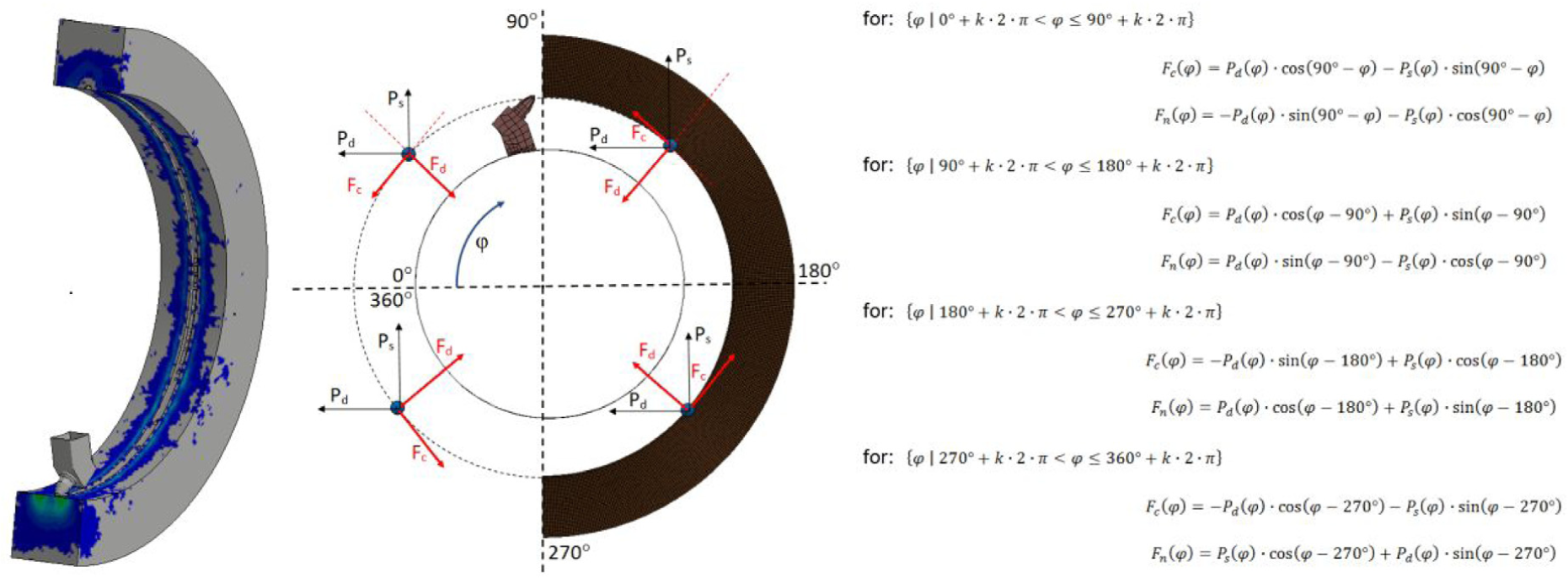
Cutting loads, numerical and mathematical model.
The resultant torque of loads during normal interactions between the cutting head and longwall in time was presented in literature as well as in the frequency domain.35,36 During the cutting of material, not only the cutter drum but also the whole structure of continuous miner tends to vibrate. There is a possibility of applying different types of passive, semi-active and active vibration-control systems, but this is usually expensive. 37 Reducing the excessive vibrations of systems is complicated and requires numerical simulations with the use of mathematical models. 38 For further investigations, the eigenfrequency no. 4 was taken into account (Figure 17). Because at that mode, the centre of cutter drum does not vibrate, the excitation frequency during cutting could be tuned to that eigenfrequency.

Continuous miner model eigenfrequency no. 4.
The next step was the identification of the vibration-control system parameters by sensitivity analysis and optimisation by tuning the excitation frequency to the eigenfrequency no. 4, which depends on angular velocity ω and system stiffness defined by parameters k1 and k2. 30
A numerical model of continuous miner used in analyses is presented on Figure 18 below, with marked node 1000001 at the centre of cutter drum and elastic elements k1 and k2. In the model, Z axis is positioned vertically and Y axis adequately is horizontal.

View of continuous miner numerical model in LS Dyna.
Figures 19–21 present displacement and velocity curves of a node located at the centre of cutter drum for two angular velocities: initial 5.236 rad/s and final 6.44 rad/s.

Displacement and velocity curves measured at the centre of cutter drum along the Y axis (node 1000001).
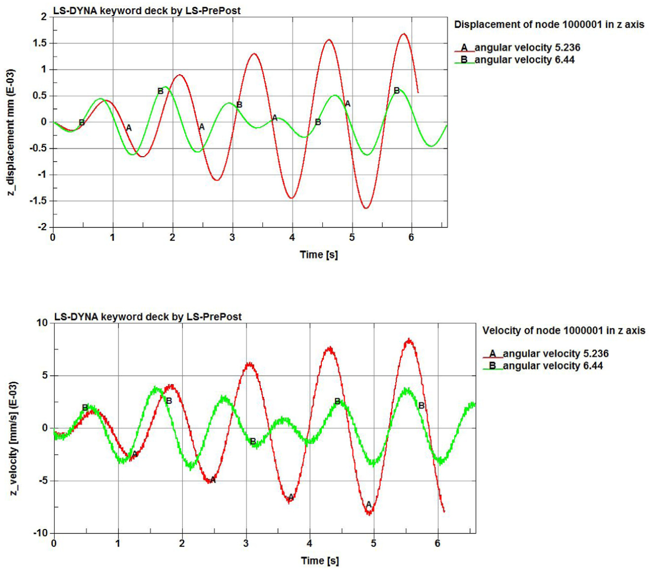
Displacement and velocity curves measured at the centre of cutter drum along the Z axis (node 1000001).

The plot of Y–Z displacements and velocities (node 1000001).
The obtained results are very promising, as the vibration of cutter drum with specified angular velocity 6.44 rad/s is reduced, exactly as it was assumed in our new concept of vibration-reduction system.
Conclusion
The growing trend clearly visible in the number of newly published patents referring to continuous miner machines is reflected in the types of deposits that are currently being exploited and scheduled for exploitation. The designs of this type of header have been evolving for more than 100 years. Throughout this time, other technologies also developed but could not be used in the former designs due to their lack of advancement. An excellent example of this is the development of cutting head designs with electric motors, as described in the article, which were not used in industrial applications despite the patents filed in this field.
The carried out analysis of the development trends confirm the possibility of returning to the concept of motors being placed inside the cutting head body. The new modular structure of the cutter drum, presented in the article, may pave the way for a new trend among manufacturers, which would certainly have a positive impact on the development of related technologies, including the PMSM motors. With electric motors inside the modular structure of the cutter drum, the concept of vibration-reduction system proposed by authors can become true.
The results of dynamic simulations indicate the efficient operation of the proposed vibration-reduction control system. This is confirmed by the displacement values of the cutting drum centre, which have been reduced to about 50%. This undoubtedly affects the improvement of reliability and fatigue of the whole structure. On the other hand, this type of control allows to support the mining process through induction of appropriate mode shapes which are able to increase efficiency of this process. This issue will be the subject of future research and development work.
Footnotes
Acknowledgements
The authors gratefully acknowledge funding by the statutory grant of the Faculty of Mechanical Engineering of the Silesian University of Technology in 2017.
Handling Editor: Wen-Hsiang Hsieh
Declaration of conflicting interests
The author(s) declared no potential conflicts of interest with respect to the research, authorship and/or publication of this article.
Funding
The author(s) received no financial support for the research, authorship and/or publication of this article.