
Abstract
The in-line inspection tool with Inertial Measurement Unit tool is becoming a routine and important practice for many pipeline companies and is effective for whole-line bending strain measurement. However, the measurements of Inertial Measurement Unit tool are always affected by noises and errors, which are caused by inherent inaccuracies and deficiencies of the experimental techniques and measuring devices. For the calculations of the bending strain, the results are very sensitive to the noises and errors. A filtering algorithm based on cubic spline interpolation was proposed for Inertial Measurement Unit data processing to eliminate noises and errors for bending strain, and the effectiveness is validated through the pipeline field test. The results showed that the average pipeline displacement deviation declined 13.82% in the three tests, and the bending strain error reduced from 0.037% to 0.014%. The proposed method effectively improves the inspection accuracy and provides an effective method for pipeline displacement and strain inspection, which ensures the safe operation of the pipeline.
Keywords
Introduction
With the continuous development of oil and natural gas, the security and rapid transportation of oil and natural gas have also become one of the important factors affecting the economic development.1,2 Due to its low transportation cost, stable transportation, and uninterrupted transportation, long-distance pipeline transportation has become the most important way for oil and gas transportation in the world at present, which is largely built on land, ocean, mountains, and other environments. 3 Because of long distance and often through the geological disaster areas, the long-distance oil and gas pipelines bear the normal internal pressure and endure bending strain due to external stress. The bending strain exist heavy metals or manufacturing defects more easily lead to pipeline failure. Therefore, regular inspection or monitoring displacement and deformation of long-distance oil and gas pipelines, evaluation of the structural integrity of the pipe body, and finding of high-risk points of large bending deformation of pipelines are very important for oil and gas pipelines.4,5
The pipeline in-line inspection (ILI) refers to the inspection device with a variety of sensors, realizing non-destructive inspection of the pipeline wall corrosion, pipeline cracks, thickness, and geometry deformation by means of transport medium in the pipeline. With the development of inertial navigation technology, it has been applied to the inspection of pipelines and at the same time to measure the status of pipeline deformation, drift, trajectory, and geographic coordinates. At present, great progress has been made in the research of pipe geographic coordinate measurement based on inertial navigation and the correction of the odometer.6,7 Pipeline centerline ILI based on inertial navigation is an effective method for the pipeline centerline positioning, displacement, and bending strain inspection.8–10 The main component of pipeline centerline ILI tool is the Inertial Measurement Unit (IMU), which provides the mapping information for the pipeline. The mapping information can predict the potential deviation, and the equivalent bending strains can be determined by the data of IMU along the pipeline. So, it is found that the IMU data can be acquired in-line and can be calculated for the bending strain of pipelines.11,12 However, the ILI measurements are always affected by some noises and errors caused by inherent inaccuracies and deficiencies of the experimental techniques and measuring devices. The calculation results of the bending strain experiments in pipeline are very sensitive to these errors, which would lead to the deviation from the real values. The risk evaluation for bending strain of the pipeline will be incorrect and it will be difficult for us to decide the repair work.
In this article, in order to improve the inspection precision of bending strain and the displacement in the pipeline, a filtering algorithm based on cubic spline interpolation for the measured data has been proposed to estimate the longitudinal displacement and bending strain in the movement region. The effectiveness of the algorithm is investigated through longitudinal displacement and bending strain field test.
Calculation method of pipeline bending strain
Total longitudinal strain in the pipe wall can be obtained by summing the strain components such as the membrane and bending strains13–15

where
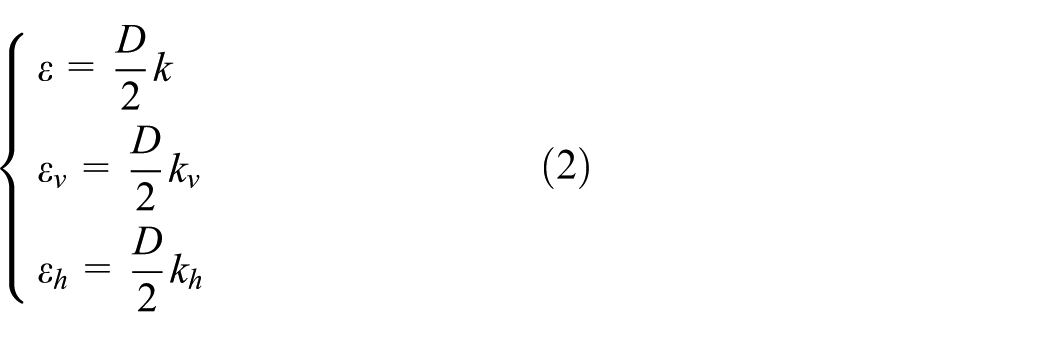
where
The total curvature of the centerline of a pipe is described at each point along the pipeline by the curvature vector. In order to calculate the pipeline curvature, the centerline of a pipe is considered as a three-dimensional (3D) parametric curve described in a Cartesian system by a vector

Assuming that the vector t is tangent to

where the pitch

Pitch
Assuming that the vector k is the curvature vector of a 3D curve at a given point, and the k consists of the vertical curvature

The above equations can be written separately for each component of the curvature vector in the Cartesian system

Based on equations (3)–(6), the components of the defined curvature vector can be calculated as follows

The vertical curvature

The Pitch
The IMU is composed of inertial devices such as accelerometer and gyroscope, the gyroscope is used to measure the angular velocity. From equation (8), the curvature k is affected by the measurement of angle of pitch and azimuth. The angle of pitch and azimuth is obtained by integrating the angular component velocity. It is important to ensure the accuracy of angle measurement to reduce the cumulative error. However, when the IMU tool passes the miter or poor weld, these features would affect the gyroscope to collect the wrong angle changes. The computation results of bending strain of pipeline are unable to reflect the present strain of pipeline, and there is a certain error between the computation results and the real values. Therefore, filtering processing is applied, as the case should be further carried out on the aforesaid computation results of bending strain of pipeline in the practical application to eliminate the interference caused by the feature such as miter or poor welds.
Measurement system configure and filtering algorithm
Measurement system configure
It is known that the IMU tool is used to measure the longitudinal displacement16–18 and relative bending strain. The pipeline centerline ILI tool with inertia measurement technology mainly consists of the following units:
Drive vehicle with battery to offer the driving force and system power.
The IMU and control unit mounted in the electronic vehicle collect the attitude information of ILI tool. Steady wheels are used to ensure the electronic vehicle to locate in pipeline centerline.
Two to four odometer wheels to measure the distance and offer the speed of the tool.
Girth weld detector can inspect the position and pass time of the each girth weld. It can be used for the alignment for every spool for repeat inspection.
Tracking system includes extremely low-frequency electromagnetic transmitter and ground maker. Figure 2 shows the pipeline centerline ILI tool with IMU.

IMU pipeline inspection tool.
The cubic spline interpolation filtering algorithm
There are many algorithms can be used to filter the test results such as interpolant, least squares, arc spline curvature, and spline interpolation filtering. The smoothness for method of interpolant is poor and only have first-order continuous derivative. The least squares method can reflect the whole trend of all data and eliminate its local fluctuations. It is suitable for disorderly discrete data fitting. But it is not ideal for the orderly discrete data fitting of each data that may reflect the change of linear trend. The curvature of the arc spline curve changes in a hopping manner, which indicates that the smoothness is poor. The cubic spline interpolation belongs to the interpolated spline curve, which has a smooth line shape and good conformal function. The accuracy of the fitting is determined by the sampling data spacing. The fitting algorithm determined in engineering practice should have certain characteristics: (1) Smoothness: the curve should have at least second-order continuity. (2) Concavity and convexity: According to the curve elements determined by the sampling data, the concavity and convexity of the sampling points should be maintained. (3) Accuracy: The result should be completely or as close as possible to raw data.
In summary, the cubic spline interpolation filtering method is adopted to ensure that the fitting curve passes all the sampling data not only to reflect the overall shape of the curve but also to display the flexibility and diversity of the detailed features. It compensates for the large error of the arc spline curve when fitting the mitigation curve.
Supposed that
Integrating

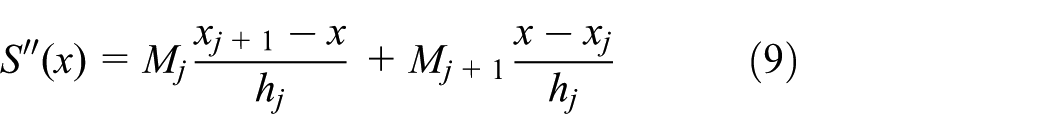
By differentiating the above equation once, the following may be obtained

By use of

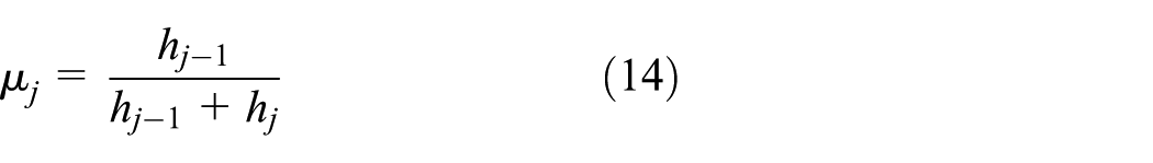
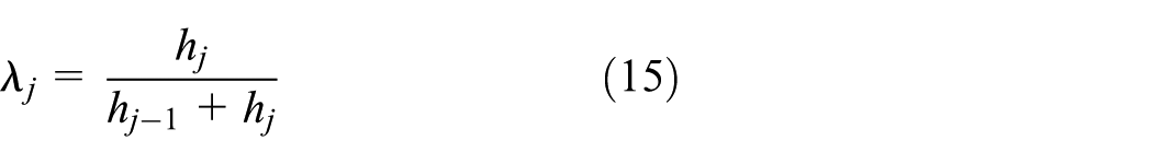
Through processing, the following may be obtained

where

Determination of boundary conditions:
1. The first derivative values at both end points of the interval are known

Then, according to equations (9)–(16), the following may be derived

2. The second derivative values at both end points of the interval are known

The special situation is

Then, the point equations of end points may be obtained

With regard to the first kind of boundary condition, make

According to equation (22), the spline function equation on each divided interval may be obtained, and the fitting curve for the strain data of pipeline is finally obtained.
Preprocessing of bending strain data of pipeline
Because the IMU in the ILI tool of pipeline centerline collects data at a certain frequency, the sampling point scale obtained by in-pipeline inspection tool at different traction speed is different, and due to the effect of welding seams or defects on in-pipeline inspection tool, the computed strain data of pipeline are different, resulting in a significant bias between the data and the real strain data in the fitting. In order to eliminate the effect of different original strain data scale, preprocessing of bending strain data of pipeline should be carried out first.
Supposed that the input variable mileage point is

where

where
Construct m dimensional vector
Field test and data analysis
Equipment and test
To test the proposed method experimentally, an IMU pipeline inspection gauge (PIG; as shown in Figure 2) is used to measure a pipeline. The test pipeline is about 100 m as shown in Figure 3. To avoid pipeline vibration, some loadings have been set up in the middle of the pipeline during the inspection. The pipeline has subsided 26.5, 10, and 5 cm, relative to original position. Seven rulers are installed in the pipeline to measure the displacement of each point, and three stain gauges are installed in the pipeline to measure the stain changes. Five steadies are installed under the pipeline; the middle steady can be lifted up and down to simulate pipeline displacement for different tests.
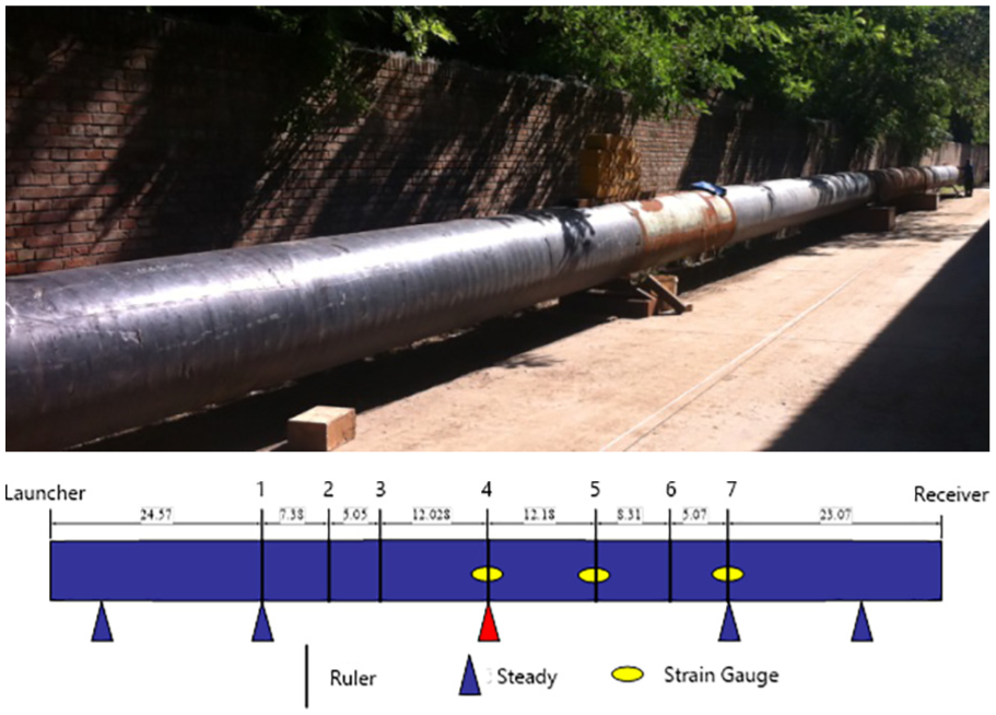
The pipeline for pull-through test.
Lots of oil pipelines are heating transportation and pass through mountains, hills, rivers and other complex environmental areas, the technical and safety requirements of electrical equipment are extremely strict because of the vibration, lash and temperature and so on during the inspection. To safely detect the actual pipeline, the IMU should consider not only the technical performance but also the actual situation of the pipe and the external environment. Technical performances of inertial devices used in the field tests are shown in Table 1.
Characteristics of sensors.

Application of the filter for the raw data
For the first round test, the pipeline has subsided for 26.5 cm. Figure 4 shows the measured displacement of actual pipeline before and after filtering.
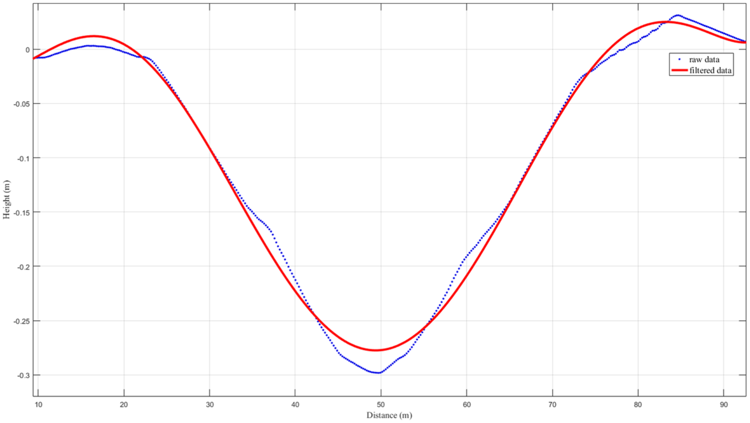
The comparison for raw and fitted measurement of first test.
In order to demonstrate the good performance of the proposed method, the other two tests have been done, which the maximum displacement of 10 and 5 cm. Seven rulers are installed in the point of pipeline to measure the actual displacement as seen in Figure 3. The raw data and filtering data for three tests are summarized in Table 2. From the three tests, the average measurement of each displacement deviation ratios decreases from 7.97%, 10.59%, and 46.64% to 4.44%, 5.01%, and 12.8%, respectively, after filtering. The average displacement deviation ratios decrease from 21% to 7.18%, and the total average deviation ratios declined 13.82% in the three tests. For example, from Figure 4, it can be seen that the filtered data have removed much noises and are more accurate.
The comparison for the measurement and filtered values of the three tests.

Figure 5 shows the same results for the test conducted three times. The dashed lines show the measurement results. The solid lines indicate the filtered data which clearly demonstrate the effectiveness of the proposed filter in smoothing the noisy data. It can be seen that the filtered data removed the oscillation and noises, producing smoothed data. With the smoothed data, the result of pipeline bending strain will be calculated.
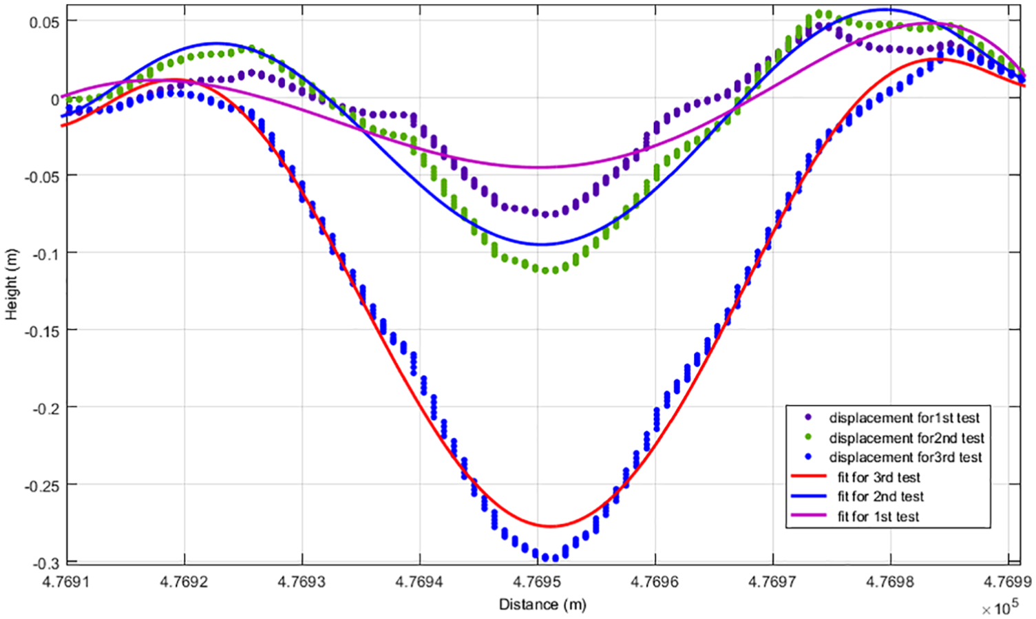
Three rounds of tests for different displacement.
It is clear that the accuracy has been improved by filtering. Due to the errors and noises for the ILI, the measurement results deviate from the actual pipeline displacement. The results reveal that the proposed method is effective and the results are close to the actual value. The filtering data are better to calculate the pipeline bending strain, which will be described in the following section.
Analysis for pipeline bending strain
Figure 6 shows the pipeline bending strain which is calculated by the method with PIG attitude information, named attitude method. These results show the pipeline deformation and bending strain when the pipeline undergoes the additional force. The calculation of the bending strain by this method is affected by the vibration and noises from pipeline, such as miter, poor welding, and pipeline internal condition. For example, for the 34 m, the bending strain showed the spike for the strain because of the girth weld. It is the interference to show the overall pipeline bending strain. Due to these factors, the interference factors should be removed in the overall bending strain. As shown in Figure 6, due to the different displacement for three times, the overall trend of the result is different. It is clear to see that the larger the displacement, the larger the bending strain. From Figure 6, it can be observed that it is difficult to show the overall pipeline deformation because of the bending strain affected by the miter and other factors.

Three times of inspection of the bending strain by attitude method.
In order to solve this problem, the calculation which uses the second derivative of filtered longitudinal displacements in equation (5) provides the distribution of bending strain. In Figure 7, the result shows the computation of the bending strain, which uses the filtered method for the pipeline displacement. It is clear to show actual deformation of the overall pipeline. It can be seen from Figure 7 that the filtered method can remove the interference of factors such as miter, poor welding, and pipeline internal condition. The computation of the bending strain can be shown by the overall pipeline deformation without interference of the local deformation.

Three times of inspection of the bending strain by filtered method.
In order to quantitatively analyze and verify the correctness of the method, three experiments were done, and the three strain gauges are installed in the pipeline for measuring the pipeline strain when the pipeline subsides the different displacements as seen in Figure 3. The strain gauges measure the different point of bending strain for the pipeline. The attitude method and the filter method proposed in this article were used to calculate the pipeline strain value. The calculation results were compared with the results of strain gauge measurement. The comparison between the measurement of strain gauge and the calculation results of the attitude method and the filter method for the subside point of each test is shown in Table 3.
The comparison of computation of attitude method and filtering method.

The result shows that the average relative error between the strain gauge measurement and computation of attitude method is 0.029%, 0.034%, and 0.022% when the pipeline displaced for 25.5, 10, and 5 cm. The average relative error between the strain gauge measurement and computation of filter method is 0.01%, 0.012%, and 0.004%. It is clear that the attitude method computed by the pitch change
Conclusion
A filtering algorithm based on cubic spline interpolation was proposed to eliminate measurement errors and noises from measured longitudinal displacements and bending strain when the IMU system is used to inspect pipeline. The proposed method was verified and tested, and a PIG is used to inspect a straight pipeline which is approximately 100 m. The results showed that the average pipeline displacement deviation declined 13.82% in the three tests, and the bending strain error reduced from 0.029%, 0.034%, and 0.022% to 0.01%, 0.012%, and 0.014%, respectively. It can be obtained that the proposed method could remove the noises and errors of displacement and bending strain from the pipeline, such as miter and poor welding without harming the measurement data, and make the calculations of longitudinal bending strain more accurate. In sum, the proposed method effectively improves the inspection accuracy and provides a novel method to practically measure for ILI purposes especially in the oil and gas pipeline industry.
Footnotes
Handling Editor: Hongfang Lu
Declaration of conflicting interests
The author(s) declared no potential conflicts of interest with respect to the research, authorship, and/or publication of this article.
Funding
The author(s) disclosed receipt of the following financial support for the research, authorship, and/or publication of this article: This work was supported by the project of “National Key R&D Program of China: 2016YFC0802100”; National Instrument special: development and application of high precision scanning laser vibration meter (2014YQ350461); National Natural Science Foundation of China (61873021) and Youth talent support program of Beihang.