
Abstract
Severe damage, such as support failure, global buckling of members, local buckling of members, fracture of members, dislocation at the end of members, and failure of bolted connections, were observed in space double-layer lattice structures following the Lushan earthquake (China, 2013, M 7.0). To study the seismic behavior of the space double-layer lattice structure with a lower supporting structure, a series of shaking table tests were conducted. A nonlinear numerical analysis was performed on the damage of the structure, in which the material parameters were obtained from material tests of the steel member. The numerical results were compared with the experimental results, and the difference between the test and the numerical simulation was presented and discussed. The validity and accuracy of the proposed numerical model used for predicting the structural damage was verified by the experimental results, which indicates that the modeling and analytical method was applicable for the analysis of the space double-layer lattice structure.
Keywords
Introduction
Space structures in the form of single- and double-layer lattice shells are widely constructed throughout the world, especially in China. This kind of structure has become larger, higher, and much more complicated in recent years, which may lead to them being more sensitive to severe earthquakes and other dynamic loads. However, most of those structures are located in seismic areas with frequent severe earthquakes, which may cause property and economic losses, even resulting in casualties. Many researchers1–3 focus on the dynamic instability since the structure is sensitive to changes in appearance, and the dynamic strength failure is also observed.4,5 The seismic performance of the space structure has been investigated using different numerical software6–9 and some analytical methods, including the response spectrum method10,11 and statistics of the responses. 12 The increment dynamic analysis4,5 was also used to investigate the structural seismic performance.
From observations of previous earthquakes, including the Northridge earthquake (USA), Kobe earthquake (Japan), and Lushan earthquake (China), we see that the connection stiffness has a significant effect on the mechanical property of the structure.13–16 The theoretical study of the seismic performance of the structure is complicated and requires consideration of many uncertainties. 4 A shaking table test is a reasonable way to study the seismic behavior of a structure, and much work has been done on the seismic behavior of steel frame structures with shaking table tests.17–21 However, these studies mainly focused on the steel frame and little attention was paid to the space double-layer lattice structure.
The space double-layer lattice structure has been significantly damaged in the Lushan earthquake (2013, China). This is far from the view of many scholars that such structures have good seismic performance. Therefore, after the Lushan earthquake, Nie et al. 16 conducted the site investigation of the earthquake damage of the space double-layer lattice structure. Nie et al. 16 give pictures of typical damages to two typical gymnasiums in the Lushan earthquake and discusses the causes of these damages. In order to investigate the effect of member buckling on seismic performance of structures, shaking table tests of space double-layer lattice structures were carried out. 21 However, the effect of buckling is not considered in the general finite element software used in seismic design of such structures in China, so the calculation results of the above method may be unsafe. The aim of this article is to propose a new modeling method to consider the dynamic effect of member buckling in high-level seismic excitation, and verify the correctness of the proposed modeling method by comparing with the test results. The simulation method considering the buckling of members is of great significance to the theoretical analysis, design, and engineering practice of such structures. In fact, the destruction of such structures in China’s Lushan earthquake (2013) also supported the conclusion of accurate numerical analysis method is much more important for this kind of structure.
The results of the shaking table tests on the space double-layer lattice structure under different seismic motions were presented. With the results of the material tests, a finite element model was built to perform the numerical nonlinear analysis, and the results were compared with the test results. The validity and accuracy of the proposed numerical model used for the structural damage evaluation were verified through experiments, which indicate that the proposed modeling and analytical method are applicable for studying and designing the space double-layer lattice structure.
Shaking table test
The strong earthquake events in Lushan (China, 2013) caused severe damage, including brittle fracture in steel structures, especially in large span gymnasium structures, such as the Lushan Gymnasium and the Lushan Middle School Gymnasium. After the earthquake, the Lushan Gymnasium was repaired at extensive cost and the Lushan Middle School Gymnasium (shown in Figure 1) was dismantled. 16 The damage in the structures from the earthquake was governed by the fracture process, including three parts: failure of the joints caused by member and bolt fracture, member buckling, and failure of the supports. The structural damage was caused by several factors, such as a high unconsidered strain rate effect, the dynamic amplification of lower supporting structure, large-scale cyclic loads, and relatively lower earthquake fortification intensity, which resulted in an overestimation of the bearing capacity and earthquake loads during the design process.

Lushan Middle School Gymnasium after the earthquake: (a) Lushan Middle School Gymnasium and (b) buckling of the member in the gymnasium.
Lushan Middle School Gymnasium, which suffered severe damage in the Lushan earthquake (China, 2013), is shown in Figure 1. This gymnasium was built after the Wenchuan earthquake (China, 2008) with financial support from Macao based on the newly revised seismic provisions of China (GB50010-2008). The Lushan Middle School Gymnasium includes two parts: the first story was used as a dining room and the second story was used as a basketball court. The roof structure is a typical double-layer lattice structure with a span of 34.5 m × 42.9 m resting on 18 supports on top of the reinforced concrete columns. The 1/10 scaled test model was simplified based on the Lushan Middle School Gymnasium, as shown in Figure 2.

Experimental model with or without isolated support: (a) model A without isolated support and (b) model B with isolated support.
With the increase in the input ground motion, the nonlinear effect of the members on the structural dynamic responses increases based on the test result. Since structural behavior varies with different seismic motions, the acceleration responses of the model are discussed from the shaking table test under the Taft (1954) and the Lsfx (2013) seismic motion with the amplitudes of 35, 100, 200, 400, 500, and 600 cm/s2. The shaking table test under the Taft seismic motion (1954) with the amplitude of 600 cm/s2 is shown in Figure 3, and the red bold line represents the original position of the member. As can be seen in Figure 3, the web members and upper members experienced severe buckling, which indicates that the space double-layer lattice structure presented an obvious deformation, but the lower support structure remained intact and the whole structure did not collapse.

Structural deformation under Taft seismic motion with an amplitude of 600 cm/s2.
Numerical simulation of the experimental results
The structural damage and collapse were largely determined by member instability, especially the instability of the web member connected with the support. From a mechanical point of view, the structural integral rigidity will change obviously if there are severe stiffness degradations in its members. The beam finite element model is used to simulate the lower steel frame structure, and the shell finite element model is used to simulate the floor. Because the lower supporting structure is in elastic state during the whole test process, the simulation of lower supporting structure is easy and it could be considered accurate. However, the different modeling methods of space truss structure will seriously affect the dynamic response of the structure. And the key of the model is whether the model can simulate the dynamic effect of member buckling.
Classical finite element analysis method
The link element is recommended during design process by Chinese seismic code, which means the structural responses obtained by numerical simulation are only accurate when the structure is subjected to small or moderate earthquakes. When geometric nonlinearity is simulated by the classical link element, the structural stiffness is recalculated according to node displacement (Figure 4(a)). According to the actual earthquake damage survey, the member AC, shown in Figure 4(b), will experience large buckling under excessive force, which makes the structural deformation obviously different from the hypothetical deformation obtained by the classical link element. Therefore, even though both material and geometric nonlinearity were taken into account in the software, the analytical method still cannot consider the geometric nonlinear effect caused by a member itself due to the characteristics of the link element. The structural displacement of the numerical simulation will be much smaller if the member buckling is ignored.

Comparison of the geometric nonlinearities between the classical link bar element and the buckling bar element: (a) geometric nonlinearity of the classical link element and (b) geometric nonlinearity after buckling of one member.
The welded joint and bolted joint are generally considered to be a rigid joint, which was verified through experimental and numerical studies by Ma et al. 22 The moment will impart to the adjacent member once member buckling occurs, which will increase the possibility of instability within the member. However, the node rotation cannot be simulated with the link element either. Therefore, in this case, it is impossible to conduct an accurate numerical simulation if the link element is used. The seismic performance will be overestimated if member bulking and node rotation are not considered.
The beam element with multiple segments can be used to simulate the global buckling of the member. The member experiences lateral bending deformation with the axial stiffness reduced under the axial force action and transverse disturbance. Herein, the nodal displacement of the member represents its real deformation form since the beam element is divided into several segments. Therefore, the effect of member deformation or member buckling on the seismic performance of the whole structure can be evaluated through two beam elements, including a straight linear beam and curved beam with multiple segments, as long as the geometric nonlinear function of the software is opened (Figure 4(a) and (b)). The geometric deformation map of members using straight linear beam under a dead load, axial pressure, and transverse disturbance conforms to the Euler buckling theory (Figure 5(a)). The geometric deformation map of members using a curved beam under the above loads conforms to the buckling theory of the China steel structure design code (Figure 5(b)). Although the beam element is more complex and computationally expensive than the link element, the efficiency of the beam element used for the strongly nonlinear analysis of large span space structures is considered acceptable. Therefore, the beam element can be used to conduct numerical simulations for large span space structures for more accurate results.

(a) Straight linear beam model and (b) curved beam model with multiple segments.
Finite element model of the scaled test model
Three kinds of elements, including the link element, straight linear beam element, and curved beam element, were adopted to describe the mechanical behavior of the members in this article. The foregoing three elements used in the numerical model were named FEM-1, FEM-2, and FEM-3 (Table 1) with the corresponding reference. 23 The numerical model is composed of a lower supporting steel frame, an upper double-layer lattice shell, and a loading wood board, as shown in Figure 6. The shaking table is set as a rigid body, and the upper part of the wood board is coupled with the node of the upper double-layer lattice shell. The parameters of the three models are the same except for the different types of elements. It can be seen from Figure 6 that the black solid lines simulated by the beam element represent the steel frame structure and the red lines simulated by the foregoing three elements represent the double-layer lattice shell. The green flat surface simulated by the shell element represents the loading wood board, the gray flat surface, and the second-floor panel. The material of the member is Q235B steel simulated by a plastic kinematic model with a Young’s modulus of 210 GPa, yield strength of 235 MPa, and failure strain of 0.1. To accurately simulate the effect of member buckling on the structural collapse, the value of initial eccentricity, which is 0.5% and determined by the actual measurement of member’s bending, was used to simulate the initial geometric imperfection of the member in FEM-3.
Model characteristics.


Numerical model of the experimental model.
Young’s modulus is increased to adjust the element stiffness of the two models due to the different length between the numerical model and the test model. The main form of the beam element deformation is bending deformation, and its geometric nonlinearity is caused by lateral displacement under an axial force. Therefore, the lateral stiffness of the beam element, which is inversely proportional with the third power of the element length, was used to adjust the member stiffness of the beam element. The axial stiffness of the bar element, which is inversely proportional with the element length, was used to adjust the member stiffness, since the main deformation form of the bar element is axial deformation (Table 2) with the corresponding reference. 24
Adjustment coefficient for Young’s modulus for the beam and link elements.

Comparison between test and numerical simulation before collapse
The analysis results for the implicit calculation method do not converge due to an unstable numerical solution caused by the distortion of the rigidity matrix when calculating the above strong nonlinearity and simulating the structural collapse. Therefore, the explicit analysis was applied in this study to obtain results from the numerical simulation using the three different elements, and the results are compared with the test results obtained from the shaking table. The finite element software ANSYS-DYNA was used to conduct the numerical simulation. The input excitation at the bottom of the finite element model adopts the actual measured acceleration obtained at the floor of the shaking table and then extracts the displacement and acceleration time history curves corresponding to the test measuring points.
The comparison of the acceleration responses between the test results and the numerical results under the two seismic motions is presented in Figure 7. All the foregoing data were filtered by the same bandwidth frequency range of 0.01–30 Hz. Due to space limitations, this article only presents the compared results of one measuring point for the double-layer lattice structure. The simulation results of the three units are acceptable when structure is still in the elastic range with input amplitude of seismic input less than 100 cm/c2. However, the results obtained from the numerical simulation using the curved beam element more closely approach the test results than the corresponding results of the other two elements with input amplitude of seismic input less than 100 cm/c2. The simulation results of the link and straight beam elements are very different from the experimental results, so the simulation accuracy is unacceptable. Even if the same element is used, the simulation accuracy will vary with different seismic motions. Even with the curved beam element, there are still some errors between the numerical results and the test results, because the acceleration responses at the measuring point located at the steel ball are enlarged by local vibration of the joint. Therefore, the acceleration responses at the model joint in the test are much higher than the actual value.
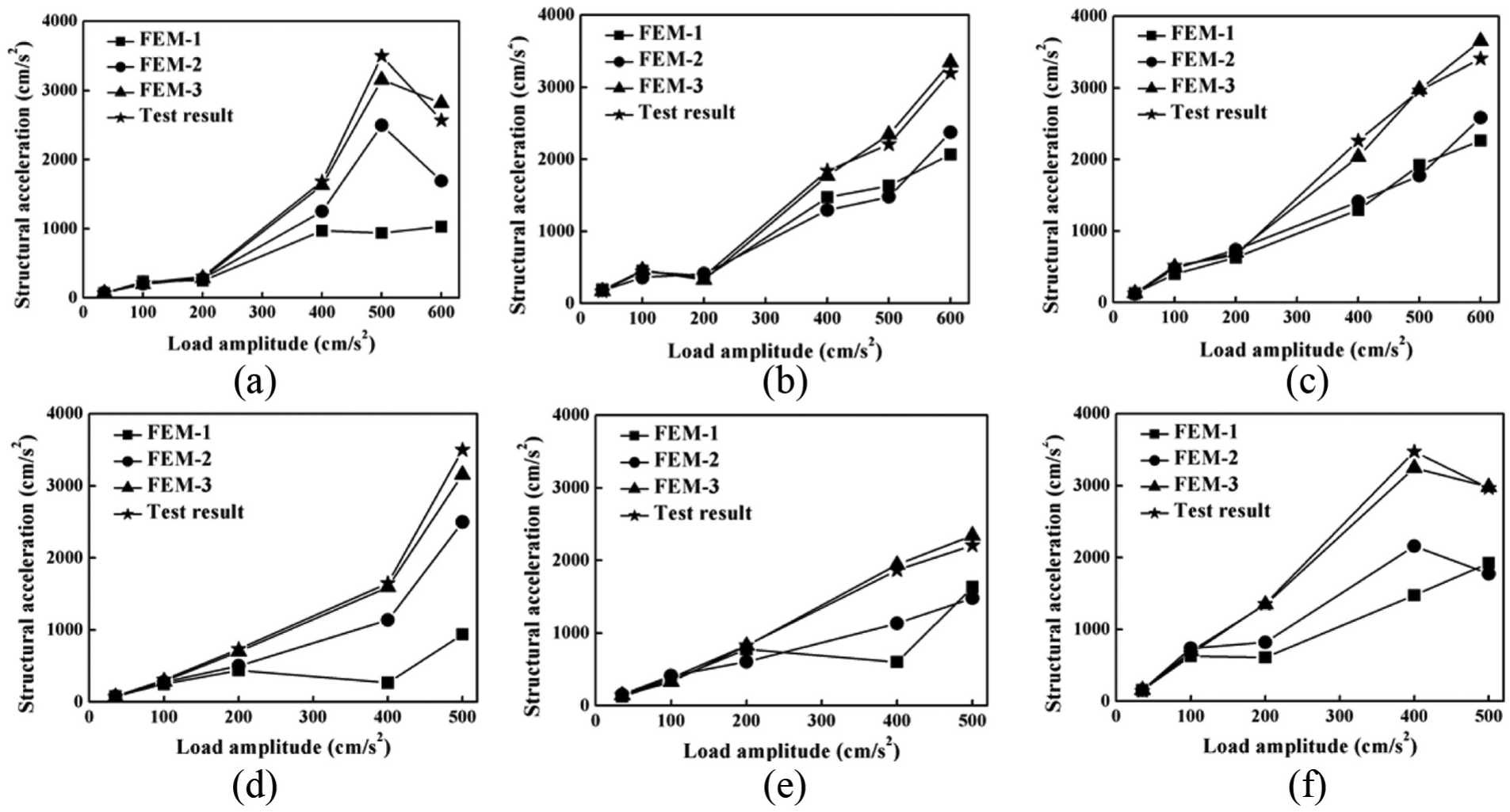
Comparison of acceleration between test results and numerical results under (a) Taft-x motion, (b) Taft-y motion, (c) Taft-z motion, (d) Lsfx-x motion, (e) Lsfx-y motion, and (f) Lsfx-z motion.
The comparison of the displacement between the test results and the numerical results is presented in Figure 8. The results of displacement simulation for the three elements show the same trend as that of acceleration simulation. From the comparison of displacement and acceleration, we can draw a conclusion that the simulation results of the three elements are close before the structure enters the plasticity with input amplitude of seismic input less than 100 cm/c2. The numerical results obtained from the model of the curved beam element are much more closely related to the test results than the corresponding results with the other two elements with input amplitude of seismic input less than 100 cm/c2, which indicate that it is appropriate to use the curved beam element in the numerical simulation. Figures 7 and 8 show that the simulation results of the three elements are close with the structure in the elastic range, that is, when the material and geometric nonlinearities do not work. However, the curved beam element should be used to conduct theoretical research and engineering design with the structure in the plastic range, that is, when the material and geometric nonlinearities are significant.

Comparison of displacement between test results and numerical results under (a) Taft-x seismic motion, (b) Taft-y seismic motion, (c) Lsfx-x seismic motion, and (d) Lsfx-y seismic motion.
The mean error can be obtained by averaging the errors of the acceleration and displacement at the center of the upper double-layer lattice shell. The relationship between the mean error and the peak value of the input ground motions is shown in Figure 9. The development trend of the mean error indicates that the error of the three models is small under an earthquake of 100 gal. The mean errors of the three models are similar under an earthquake of 100 gal, which indicates that the geometric nonlinear effect of the component caused by the disturbance is not obvious under small seismic motion. However, with an increase in the input acceleration peak, the mean errors of models FEM-1 and FEM-2 increase, while the mean error of FEM-3 is more stable with a value of less than 10%. The mean error of FEM-2 is between FEM-1 and FEM-3. With an increase in the ground motion, the analytical mean errors of FEM-2 gradually deviated from that of FEM-1, which indicates that the effect of the geometric nonlinearity caused by the disturbance increases and this effect on the structural seismic behavior also increases. The difference in the analytical error between FEM-2 and FEM-3 is very obvious, which indicates that the initial eccentricity of the member has significant influence on the analysis result under strong seismic motion.
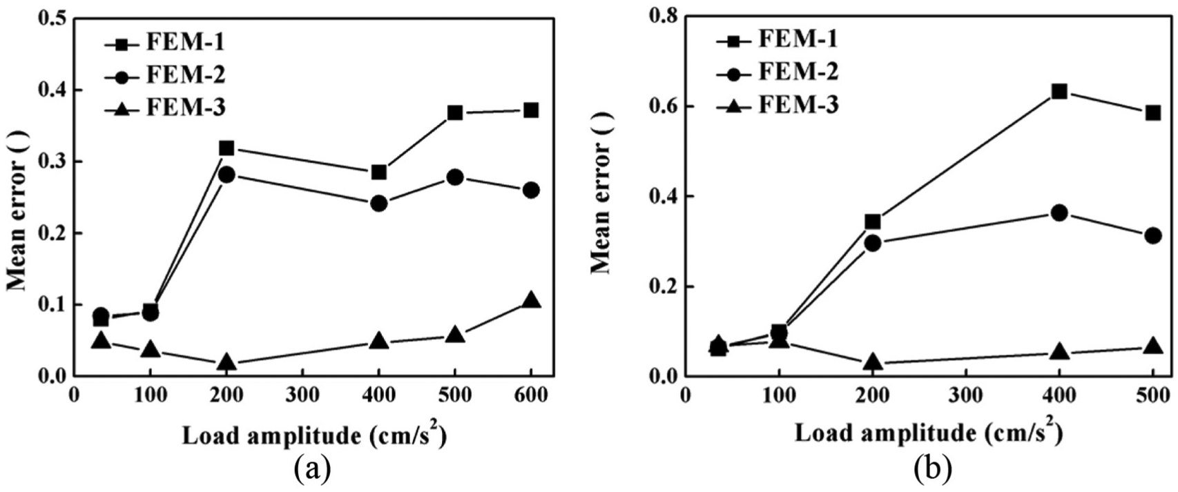
Relationship between the mean error and the peak value of the input ground motions: (a) mean error under Taft-x seismic motion and (b) mean error under Lsfx seismic motion.
The structural deformation of simulation result using FEM-3 under the Taft seismic motion with the amplitude of 600 cm/s2 is shown in Figure 10. The structural deformation obtained by the curved beam element is more consistent with the corresponding deformation obtained by the shaking table test as shown in Figure 3. Therefore, the simulation accuracy of FEM-3 is much more accurate than the results based on the link element and the straight beam element. As can be seen from Figure 10, FEM-3 can accurately simulate the structural failure state, deformation, and member buckling which are of great significance for seismic theoretical research and engineering design of space structure.

Numerical simulation results of FEM-3 under Taft seismic motion with an amplitude of 600 cm/s2: (a) structural deformation of FEM-3 with wood board, (b) structural deformation of FEM-3 without wood board, (c) structural deformation of FEM-3 from another side, and (d) top view of structural deformation of FEM-3.
Comparison of collapse between the test and numerical simulation
The test structure experienced collapse under the Taft seismic motion at an amplitude of 700 cm/s2. The structure presented severe deformation under the Taft seismic motion with an amplitude of 600 cm/s2, which indicated that plastic deformation should be considered in the numerical simulation. The two input Taft seismic motions were combined and a certain time interval with the amplitude of 0 was added between the two. All sensors were removed from the structure when observing the earthquake damage of the structure collapse in the test.
The incremental dynamic analysis method was adopted to study the failure characteristics of FEM-1 and FEM-2. The input of the Taft motion (0.6 g) was also scaled up during the analysis in order to consider the effect of plastic deformation in the shaking table test. The collapse of structural model is shown in Figure 11(a) and (b).

Numerical simulation of the shaking table test at the collapse state using FEM-1 and FEM-2 models: (a) front view of collapse of the test model, (b) side view of collapse of the test model, (c) collapse of FEM-1 under 20 times of the actual motion, (d) plan view of collapse in FEM-1 model under 20 times of the actual motion, (e) collapse of FEM-2 under 1.3 times of the actual motion, and (f) plan view of collapse in FEM-2 model under 20 times of the actual motion.
FEM-1 experienced collapse when the input acceleration reached 20 times the initial input motion with the amplitude of 700 cm/s2. The corresponding axonometric projection, elevation, and plan view are shown in Figure 11(c) and (d). The failure pattern is the collapse of the lower support frame but the upper double-layer lattice structure does not suffer serious damage even under such strong earthquake motion, which completely deviates from the actual seismic damage of the shaking table test. The node of FEM-1 is a hinge connection and the node is free of moment transmission due to the characteristics of the shape function, which results in the stress state of the structure always remaining in the most stable position. FEM-1 cannot account for the dynamic effects of geometric nonlinearity of the member, so FEM-1 has a significant flaw in evaluating the seismic performance of a space double-layer lattice shell under strong earthquakes. In this test, the lower structure design of the test model is conservative in order to eliminate the influence of nonlinearity of the lower supporting structure on the upper structure under the strong earthquake, which also makes FEM-1 fail in simulating the collapse of the test model.
FEM-2 has no visible plastic deformation under Taft motion with the amplitude of 700 cm/s2. FEM-2 experienced collapse when the input acceleration reached 1.3 times the initial input motion with the amplitude of 700 cm/s2. The corresponding axonometric projection, elevation, and plan view are shown in Figure 11(e) and (f). The collapse of FEM-2 is close to the collapse of shaking table test (see Figure 11(a) and (b)), which indirectly indicates that the analysis results of the beam element overestimate the seismic capacity of the structure by 30% under severe earthquake conditions.
No obvious deformation can be found in the numerical results based on FEM-1 and FEM-2, so this article only presents the comparison between the test results and the numerical results using FEM-3, as shown in Figure 12. Buckling of the web members in one support caused the collapse of the upper structure, which was obviously affected by strong geometric nonlinear deformation of some members. The direction of the structural collapse has an obvious relation with the seismic motion records, distribution of the stress state, and the eccentricity of the member. However, the eccentricity of the members was uniform in the numerical simulation, which was different from the uneven distribution of the eccentricity in the experimental structure.

Comparison of collapses between test and numerical models: (a) collapse of the test model with roof structure, (b) collapse of the test model without roof structure, (c) collapse of the numerical model with roof structure, and (d) collapse of the numerical model without roof structure.
Conclusion
Through performing the shaking table test on a space double-layer lattice shell and the corresponding numerical simulation using the link element, straight linear beam, and curved beam, the following conclusions can be drawn.
There is severe buckling in the web members and the upper members under the Taft motion with an amplitude of 600 cm/s2, which indicates that the double-layer lattice structure presented an obvious deformation. The experimental model experienced collapse under the Taft motion with an amplitude of 600 cm/s2. The serious damage of the model verifies that the structure has the risk of damage, and even collapse, according to the existing seismic code design.
With the increasing ground motion input, the analytical error of the link element gradually increased. The final collapse pattern and ultimate bearing capacity using the link element are very different from the test results, which seriously overestimate the seismic performance of the actual space steel structure, so it is not suitable to use the link element for elasto-plastic analysis under severe earthquake conditions. The link element should be used with caution when the space double-layer lattice structure reaches a plastic state.
The damage of the space double-layer lattice structure due to the strong geometrically nonlinear dynamic process caused by member buckling can be simulated by both the straight linear and curved beam elements. The seismic performance of the structure is overestimated, since the straight linear beam element does not take into account the initial eccentricity. The dynamic performance of the structure is overestimated when the straight linear beam element is used to conduct the numerical simulation.
The analysis accuracy of the curved beam element is much better than the other two elements and the simulation of structural failure is also the closest to the experimental phenomena. Therefore, we suggest using the curved beam element considering the failure mechanics of steel to conduct the numerical simulation of the elastic–plastic behavior of a space double-layer lattice structure under severe earthquake conditions.
Footnotes
Acknowledgements
The authors are very grateful to Dr Hui-huan Ma, who has done a lot of polishing work.
Handling Editor: MA Hariri-Ardebili
Declaration of conflicting interests
The author(s) declared no potential conflicts of interest with respect to the research, authorship, and/or publication of this article.
Funding
The author(s) disclosed receipt of the following financial support for the research, authorship, and/or publication of this article: This study was jointly sponsored by the China Earthquake Administration Fundamental Research Program (nos 2017D06, 2018B12, and 1520470000001630080301), the National Natural Science Foundation of Heilongjiang Province, China (no. E2016071), the Program for Innovative Research Team in China Earthquake Administration, the Natural Science Foundation from the Education Department of Anhui Province (no. RD17100030), and the National Natural Science Foundation of China (no. 41702311).