
Abstract
Under the background of the rapid development of today’s aerospace industry, the bearing characteristics of planetary roller screw drive under high overload conditions are studied. Designing a high-load, high-performance precision planetary roller screw drive is of practical and significant. An axially spaced RV type planetary roller screw with a single nut is designed under aerospace conditions. Under the conditions of the aerospace working load and efficiency, the parameters and structures of the planetary roller screw are completed. Based on this, the bearing characteristics of the planetary roller screw are studied and the equivalent finite element model of the planetary roller screw is analyzed. Those analyses include stress and strain, elastic–plastic properties, transmission efficiency, and dynamic load capacity. The results show that the design of planetary roller screw meets the design requirements for aerospace conditions. And the results can provide a basis for the design and manufacture of planetary roller screws under high loads.
Introduction
A planetary roller screw is a mechanical transmission that converts rotational motion into linear motion or vice versa. 1 It differs from the usual ball screws used in our daily life, because that the load transmission element is a threaded roller, 2 that is, six to eight thread rollers are installed in the planetary arrangement around the main thread screw. In this way, the rotary motion of the motor is converted into the linear motion of the nut. Due to the more advanced design principles of the planetary roller screw, 3 the radius of curvature of the parts at the contact site is larger and the number of contact surfaces is larger. As a result, the force bearing contact surface of the lead screw is greatly increased,4–6 so that the bearing capacity and rigidity of the planetary roller screw are improved by several times compared with the ordinary ball screw.7,8 It can withstand tens of thousands of hours of heavy loads in an extremely hard working environment. Planetary roller screws are ideal for applications with high frequent work schedules, high carrying capacity, and high precision, such as the medical industry, optical equipment, robotics, precision machine tools, and aerospace industry.
Due to the excellent design principle and excellent performance of the planetary roller screw, 9 the mechanical properties of the roller screw are also the direction of many mechanical researchers.7,10–15 For example, SA Velinsky and colleagues16,17 analyzed the kinematics and efficiency of planetary roller screw drives. Kinematic analysis includes the derivation of angular and axial movements, and the development of sliding patterns between contact parts. The results show that for any planetary roller screw sliding movement always takes place. F Abevi et al. 18 studied the static load distribution and axial stiffness of the planetary roller screw mechanism. In the article, an original method was proposed to calculate the static load distribution and axial stiffness of the planetary roller screw mechanism, and the different components of the mechanism and their interactions were simulated by the use of rod, beam, and nonlinear spring structures. This nonlinear model describes the details of the mechanism and captures the shape of the nut and the bending deformation of the roller. SJ Ma et al. 19 studied the optimization design and contact analysis of planetary roller screw. Based on the transmission principle of the planetary roller screw, the half of the thread angle and the tooth thickness of the pitch circle diameter are used as the optimal variables to minimize the meshing gap of the thread pair. Then use the optimization module of MATLAB software to get the optimal structure parameters. At the same time, the three-dimensional model of the planetary roller screw structure was established using Solidworks, and finite element contact analysis was performed using Ansys. Calculate contact deformation and stress distribution between the screw, roller, and nut.
In this article, the parameters and structural design of the planetary roller screw are completed in accordance with the requirements of the load and efficiency of aerospace conditions. The basic study of the load characteristics of planetary roller screws, including the analysis of stress-strain, elastic–plastic properties, transmission efficiency, and anal subjected dynamic loads, compares the results with those required under aerospace conditions. It provides the basis for the design and manufacture of planetary roller screws under high loads.
Design of planetary roller screw under aerospace conditions
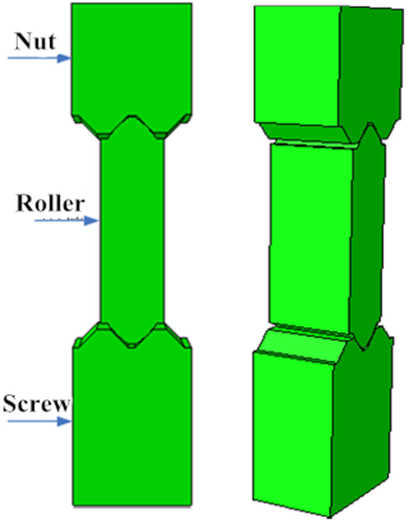
In this article, a single nut is designed for the transmission mechanism in the aerospace conditions, and a planetary roller screw with axial clearance RV type is provided. The main components of the planetary roller screw shown in Figure 1 are screw 1, its thread profile is a right angle triangular thread (at least 3 threads); nut 7, its internal thread profile is the same as the screw; roller 5, whose thread profile is a right angle circular arc thread (single head thread), has a cylindrical pivot and gear at the end of each roller. The pivot is mounted in the round hole of the baffle 2, which ensures a uniform radial distribution of the rollers. The gear teeth mesh with the ring gear 4, which allows the roller to run smoothly in the axial direction. Retainer ring 3, used to lock the flap. The flat key 6 is used to connect the transmitted objects. The structure is simple, easy to disassemble and install, and is good for neutrality, suitable for high speed, bear load, and impact.

Schematic diagram of planetary roller screw. 1: lead screw; 2: bezel; 3: retaining ring; 4: ring gear; 5: roller; 6: flat key; 7: nut.
We can know that the threaded raceways in the first few leads are subjected to the highest pressure, and the subsequent pressure is gradually reduced. Therefore, as long as the requirements of the first few leads are met, the whole can meet the requirements. So the parts studied in this article are within the first few leads.
The design of the aerospace working conditions of the planetary roller screw roller and screw thread tooth and the specific geometry are shown in Figure 2. The thread profile of the screw and nut is shown in Figure 3. The thread profile of the roller is shown in Figure 4. 3

Geometry of roller and screw threads.

Thread profile of screw and nut.
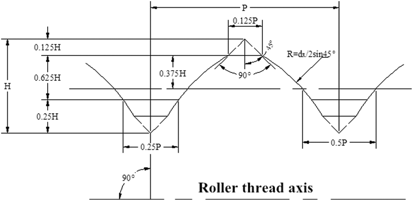
Thread profile of roller.
Aerospace precision transmission requires a rated static load of 68 KN and a rated dynamic load of 55 KN.
The design parameters of the planetary roller screw are The nominal diameter of the screw
Structural parameters of planetary roller screw under aerospace conditions.

According to the structural parameters of the planetary roller screw under the aerospace conditions in Table 1, the structural dimensions of the shaft end baffle, the ring gear, the retainer ring, and the flat key can be obtained as shown in Table 2.
Structural dimensions of shaft end baffles, ring gears, retainer rings, and flat keys.

Bearing characteristics of planetary roller screw under aerospace conditions
Equivalent finite element model of planetary roller screw
The planetary roller screw is mainly loaded in the axial direction, and the corresponding elastoplastic deformation is mainly reflected in the axial direction. Therefore, the elastoplastic finite element model of the planetary roller screw should be equivalent to the axial model of the over-axis. The axial surface model of the planetary roller screw can be seen as the roller rolling in the thread groove formed by the screw and nut, as shown in Figure 5. To sum up, the equivalent finite element model of the planetary roller screw is shown in Figure 6.

Planetary roller screw model.
The equivalent finite element model of planetary roller screw.
Stress and strain analysis
The Mises stress cloud at a nominal static load of 340 N is shown in Figure 7.

Mises stress cloud diagram of the equivalent model of planetary roller screw.
From the planetary roller screw equivalent model Mises stress cloud diagram 7, it can be seen that the planetary roller screw load transmission is transmitted from the nut to the screw rod through the roller. In the nut and roller, the stress in the contact area between the roller and the screw is larger than in other areas. This is because under the action of the external load, the contact areas are pressed against each other and stress is generated. The maximum stress value is 1.109 × 10³ MPa, and this maximum stress occurs in the area of the middle diameter of the roller that is in contact with the screw. At the same time, it can be seen from the figure that the roller is subject to higher stress and its bearing capacity is higher. In order to improve its service life, the hardness value of the roller must be within a certain index range during hardened treatment. Planetary roller screw is made of hardened GCr15. Its maximum allowable stress is 2.300 × 10³ MPa, and its yield stress is 1.700 × 10³ MPa. The maximum stress value is within the allowable stress range and meets the working load requirements.
It is known from the true strained LE cloud diagram of the planetary roller screw equivalent model (Figure 8). The strain of the planetary roller screw occurs in the contact area between the nut and the roller, the roller and the screw, and in the vicinity of the contact area, which is the center of the roller. The former is because the contact area is the range of force, and the latter is due to the force transmitted to the screw through the roller. The true strain in the nut and the roller, the contact area of the roller and the screw is larger than other parts. The maximum true strain value is 2.759 × 10⁻³. This maximum true strain occurs at the mid-thread area of the inner thread of the nut in contact with the roller.

True strained LE cloud diagram of the equivalent model of a planetary roller screw.
From the equivalent plastic strain PEEQ cloud diagram of the planetary roller screw equivalent model (Figure 9), PEEQ = 0, that is, no plastic deformation occurred. This is because the maximum stress value is 1.109 × 10³ MPa and less than the yield stress 1.700 × 10³ MPa.

Equivalent plastic strain PEEQ cloud diagram for planetary roller screw equivalent model.
Elastoplastic analysis of planetary roller screws
According to the above analysis of the finite element analysis steps of the planetary roller screw under rated load under aerospace conditions, the limit values of the plastic deformation of the planetary roller screw and the stress–strain relationship of the loading and unloading of the plastic deformation process are studied. It should be pointed out that when using ABAQUS to analyze the elastoplasticity of planetary roller screws, the plastic material parameters need to be defined, as shown in Table 3.
Plastic material parameters of planetary roller screws.

From Figure 10, it can be seen that the stress in the contact area between the nut and the roller and the roller and the screw is larger than that in other regions. Only because of the external load, the contact areas are pressed against each other and stress is generated. The maximum stress value is 1.709 × 10³ MPa, and this maximum stress occurs at the area of the roller’s middle diameter at the point where it contacts the screw. The yield stress of the planetary roller screw is 1.700 × 10³ Mpa, and plastic strain occurs. At this time, the external load applied to the nut model is 449.79 N. This means that the planetary roller screw has a static load of 107.950 KN. This shows that the axial static load of the designed planetary roller screw is larger than the rated static load of 68 KN required by space conditions, which is 1.6 times the rated static load of the transmission under aerospace conditions. That is, the designed planetary roller screw can fully meet the requirements of space conditions.

Elastic–plastic Mises stress cloud diagram of the equivalent model of planetary roller screw.
Figure 11 shows that the strain of the planetary roller screw occurs in the contact areas between the nut and the roller, the roller and the screw, and the vicinity of the contact areas as well as most of the center of the roller. The former is because the contact area is the range of force, and the latter is due to the force transmitted to the screw through the roller. The true strain in the nut and the roller, the contact area of the roller and the screw is larger than other parts. The maximum true strain value is 4.103 × 10⁻³. This maximum true strain occurs in the area of the roller diameter that is in contact with the screw.

Elastoplastic real strain LE cloud diagram of the equivalent model of planetary roller screw.
According to Figure 12, the maximum equivalent plastic strain is 3.143 × 10⁻⁴, that is, PEEQ >0, and plastic deformation occurs. In addition, whether the plastic strain occurs can also be demonstrated by the AC YIELD cloud diagram shown in Figure 13. Because the results of AC YIELD and PEEQ are always the same, when the plastic deformation occurs, the AC YIELD at the element integration point is 1 and the PEEQ is greater than 0. When the plastic deformation does not occur, the AC YIELD at the element integration point is 0 and the PEEQ is greater than 0. Under normal operating conditions, the total plastic deformation of bearing parts in contact does not exceed one ten-thousandth of the diameter of the rolling element. 20 According to Hooke’s law, the total plastic deformation of the roller is


Equivalent plastic strained PEEQ cloud diagram of planetary roller screw equivalent model.
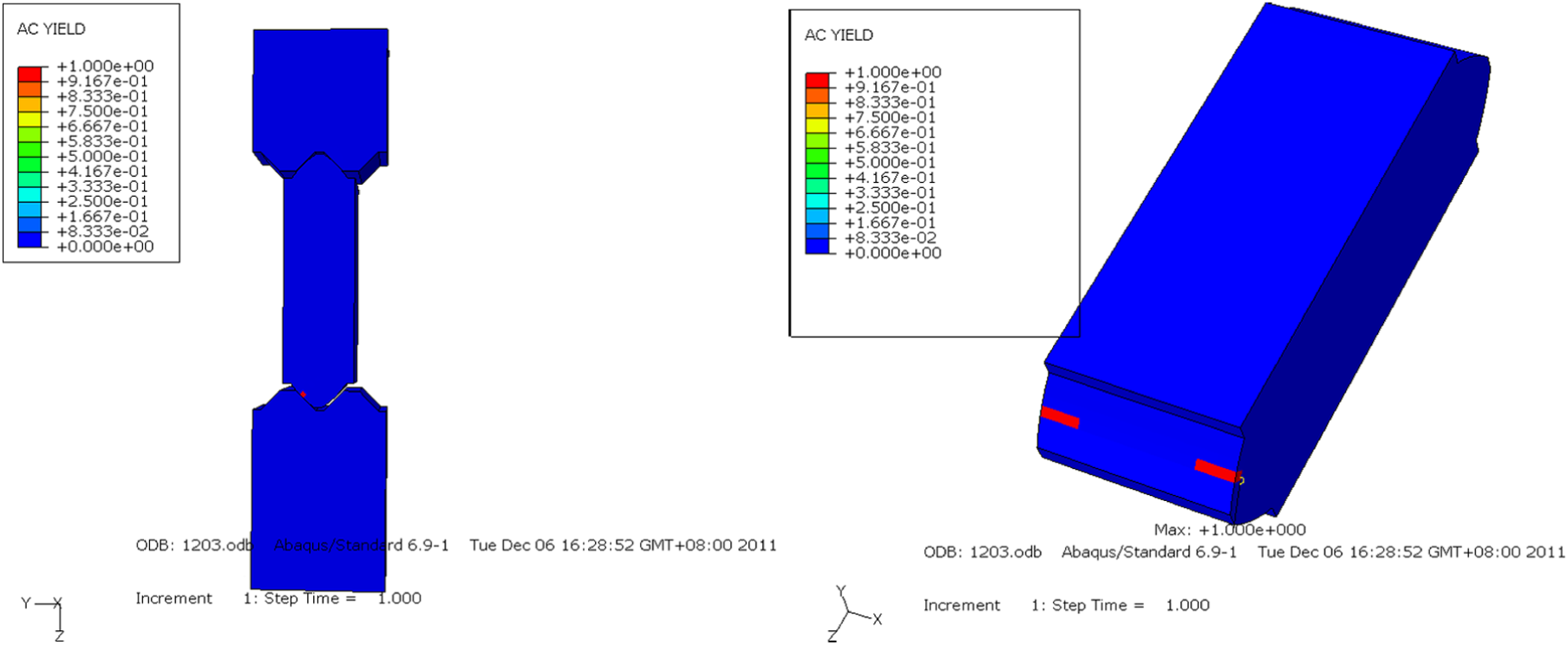
AC YIELD cloud diagram of the planetary roller screw equivalent model.
Therefore, the planetary roller screw can still work normally when plastic deformation begins. It also shows that the design of planetary roller screw can run stably under high-load conditions.
The strain–stress relationship of the plastic roller strained by the ABAQUS post-processed planetary roller screw is shown in Figure 14. It can be seen that the relationship between strain and stress is similar to the theoretical parameter of plastic strain.

Plastic strain–stress relationship of planetary roller screw.
Refer to SKF’s RV type single-nut, planetary roller screw with axial clearance. Table 4 shows the experimental data of the load and deformation. Comparing the obtained load and deformation simulation data with the abovementioned product experimental data, based on the comparison results obtained by MATLAB software, as shown in Figure 15.
Experimental data of load and deformation of SKF RV planetary roller screw.


Comparison of deformation and load of planetary roller screws.
According to Table 4 of the planetary roller screw load and deformation experimental values and finite element simulation results, programming in MATLAB to obtain the comparative results shown in Figure 15.
As can be seen from Figure 15, the simulation values and the experimental values are generally the same, and the values at the initial stage are quite different. This is because the material of the planetary roller screw used in the experiment was processed, and the simulation process cannot reflect the results of material processing. As the external load gradually increases, the bearing characteristics of the designed planetary roller screw are consistent with experimental data. At the same time, the results also show that the equivalent finite element model of the planetary roller screw set up in this chapter is reasonable.
Analysis of transmission efficiency of planetary roller screws
The efficiency of the planetary roller screw is calculated as the ratio of the output torque to the input torque 21


Among them α is the helix angle; μ is the rolling friction coefficient

The efficiency formula of the planetary roller screw shown in Figure 16 can be obtained from the formula of the efficiency of the planetary roller screw, and the relationship between the spiral lifting angle and the friction angle. From this efficiency graph, it can be seen that when the friction angle is constant, the efficiency of the planetary roller screw increases with the increase of the helix angle. Since increasing the helix angle will reduce the meshing quality and reduce the screw diameter, 22 the helix angle should be reduced as much as possible while meeting the transmission efficiency. At this time, the friction angle should be reduced and the friction coefficient should be reduced. From the figure, we can see that when the efficiency is between 0.80 and 0.90, there are two cases: the helix angle is 7°–7.4°, and the friction angle is 0.8°–1.8°; the helix angle is 13°–30°. At this time, the rubbing angle is 1.9°–3.0°. The spiral angle of the planetary roller screw designed in this article is 7.26°, the friction angle is 0.79°, and its efficiency is

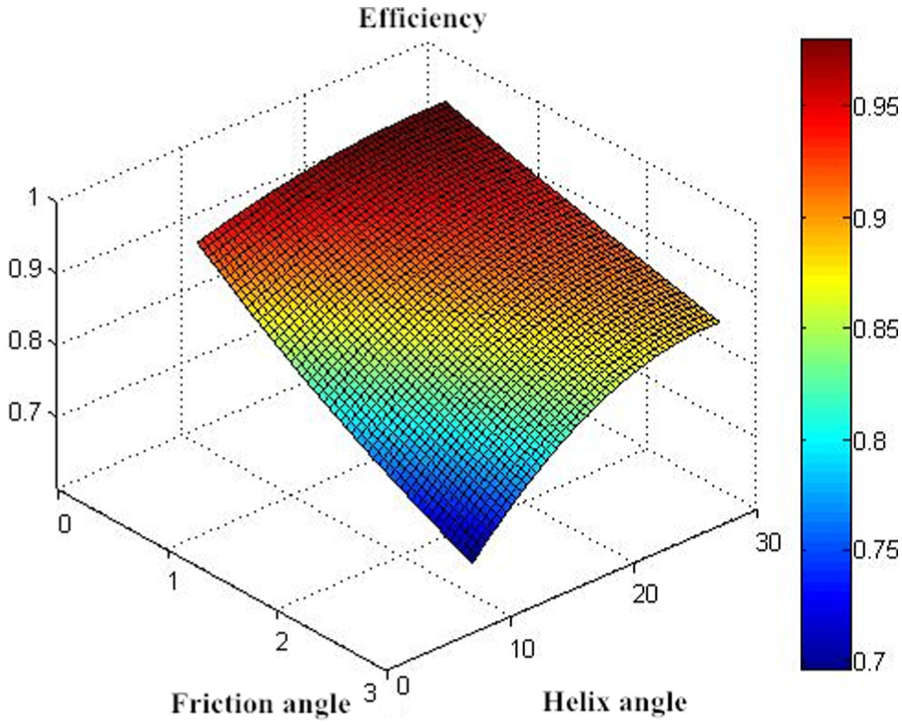
The relationship between the efficiency of a planetary roller screw and the helix angle and friction angle.
The design of the planetary roller screw transmission efficiency is 90%, to meet the requirements of the transmission mechanism under the aerospace conditions.
Analysis of dynamic load bearing of planetary roller screws
The planetary roller screw is transmitted from the nut to the screw through the contact point shape and number of loads. The shape and number of contact points define the dynamic load (Ca) of the system as 21
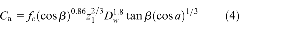
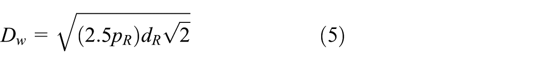
In the formula,
The planetary roller screw designed in this article

The rated dynamic load of the transmission under aerospace conditions is 55 KN. It can be seen from the comparison that the dynamic load of planetary roller screw under aerospace conditions
Conclusion
This article focuses on the design of planetary roller screws based on aerospace high-load operating conditions. And the study of the bearing characteristics of the designed planetary roller screw. These include stress–strain analysis, elastoplastic analysis, transmission efficiency analysis, and dynamic load analysis of planetary roller screws. The data obtained from the Institute and the conditions required by the space flight conditions were compared and analyzed, and the following conclusions were drawn:
Stress and strain analysis: The rated load of 340 N was applied. It can be known from the Mises stress cloud diagram of the planetary roller screw equivalent model that the maximum stress occurs in the area of the roller contact with the screw, with a maximum value of 1.109 × 10³ MPa. It can be known from the strain LE cloud diagram that the maximum true strain occurs on the medium diameter area of the inner thread of the nut in contact with the roller, and the maximum true strain value is 2.759 × 10⁻³. From the strain PEEQ cloud diagram, PEEQ = 0, that is, no plastic deformation occurred.
Elastoplastic analysis: The elastoplastic Mises stress cloud diagram of the equivalent model of the planetary roller screw shows that the maximum stress occurs at the area of the roller middle diameter where the screw meets, and its value is 1.709 × 10³ MPa. Exceeded the yield stress 1.700 × 10³ MPa, plastic deformation occurred. At this time, the static load on the planetary roller screw reached 107.950 KN, indicating that the axial static load it bears is greater than the rated static load of 68 KN required by space conditions. At the same time, according to Hooke’s law, the total plastic deformation is 6.286 × 10⁻⁴ mm, which is less than one ten-thousandth of the diameter of the rolling element, that is, 8.33 × 10⁻⁴ mm. Therefore, it can be known that the planetary roller screw can still work normally when plastic deformation begins, and it also shows that the designed planetary roller screw can operate stably under high-load conditions.
Transmission efficiency analysis: From the efficiency formula of the planetary roller screw, we can see that when the friction angle is fixed, the efficiency of the planetary roller screw increases with the increase of the helix angle. At the same time, increasing the helix angle will reduce the meshing quality and reduce the diameter of the screw, so when satisfying the transmission efficiency, the helix angle should be reduced as much as possible. The spiral angle of the planetary roller screw designed in this article is 7.26°, and the friction angle is 0.79°. It is calculated that the transmission efficiency of its efficiency is 90%. Satisfy the requirements of the transmission mechanism under aerospace conditions.
Dynamic load analysis: The dynamic load of the planetary roller screw under aerospace conditions is calculated from the dynamic load formula is
Footnotes
Handling Editor: Zengtao Chen
Declaration of conflicting interests
The author(s) declared no potential conflicts of interest with respect to the research, authorship, and/or publication of this article.
Funding
The author(s) disclosed receipt of the following financial support for the research, authorship, and/or publication of this article: This paper was supported by National Science and Technology Major Project (2016ZX04004007).