
Abstract
A nonlinear dynamic model is developed to analyze the stability of a pilot-operated valve-control hydraulic system. The dynamic model includes motion of the valve spool and fluid dynamics in the system. Characteristics such as pressure flow across the valve port and orifices, pressure, and flow rate in valve chambers are taken into consideration. Bifurcation analysis is proposed and examined by numerical simulation results when the feedback orifice diameter changes. The effects of different system parameters such as pilot-operating pressure, spring stiffness, and overlap of inlet port on the stability border of the system are studied by two-dimensional bifurcation analyses. The study identifies that bifurcation can occur in the system and lead to sustained self-excited vibration with parameters in certain region of the parameter space. It suggests that the vibration can be effectively predicted and prevented by selecting system parameters from the asymptotic stable parameter region.
Introduction
Features of a pilot-operated hydraulic actuator servo system, such as large flow rate, excellent pressure regulating, and high payload capabilities, make it suitable for actuator servo systems in various fields ranging from molding industry to automobile. 1 The demanding performance of a valve-controlled actuator system is fast response, high accuracy, and stable, among which stability is the precondition. 2 Many researchers have studied the modeling and dynamic characteristic analysis of hydraulic valves.3–5 Self-excited vibration induced by the inherent nonlinear characteristics of valve spool motion coupled with fluid dynamics can be generated during working state of the hydraulic systems due to inappropriate system parameters, which causes the system to sustain instability and leads to unexpected performance and hardware damage.6,7 A thorough understanding of stability and vibration suppression of the system is a problem of great practical significance for optimizing the performance of the hydraulic servo system.
Modeling and numerical simulations have been utilized to investigate the pressure oscillations caused by dynamic interactions of fluid and valves since early 1950s. One of the first contributions of the topic is the study of Lee and Blackburn, 8 which have shown that instability can be produced when the change of flow rate through the valve is large enough. In further studies, Noton and Turnbull 9 investigated the oscillation of a four-way valve when the fluid reaction force imparts sufficient energy to valve spool during closure. Amplitudes and frequencies of oscillation can be derived with describing functions of the system. Hayashi and Ohi 10 and Hayashi 11 focused on instability and self-excited vibrations occurring in poppet valves used in hydraulic systems by numerical simulation, taken hysteresis of the flow force acting on the poppet valve into consideration, but the coupling effect between valve and other components was neglected. Kremer and Thompson 12 developed a program based on closest Hopf bifurcation theory to provide practical rigorous stability robustness prediction design and analysis of nonlinear hydraulic system, a pressure relief valve was analyzed based on the proposed method. 13 Halanay et al. 14 studied the stability of an ideal four-dimensional nonlinear model of “two-land-four-way” spool valve with no overlap or underlap. The stability of its equilibria was analyzed using a theorem of Lyapunov and Malkin to handle the critical case due to the presence of zero in the spectrum of the matrix of the linear part around equilibria. A dynamic model was developed by Ye and Chen 15 to study the dynamic characteristics and stability of a pilot-operated two-stage solenoid valve used in pneumatic system. Soft self-excited vibration, period-one hard self-excited vibration, period-two vibration, and period-four vibration occurred with the quasi-steadily increase in supply pressure or supply flow rate were studied. Wait and Goldfarb 16 conducted a model-based stability and performance analysis of a position–velocity–acceleration–controlled pneumatic actuator. The study indicated that supplementing the pneumatic actuator with mechanical damping can significantly increase the gain margin, tracking accuracy, and disturbance rejection of a closed loop–controlled pneumatic servo actuator. Naseradinmousavi 17 carried out stability analysis of a pilot-operated butterfly valve with the aid of Routh–Hurwitz criteria. Harmful nonlinear phenomena such as chaos and crisis were investigated by nonlinear analysis. Hos and colleagues18–20 have done sufficient work on stability and grazing bifurcation of pressure relief valve. Chattering behavior that occurs when the valve poppet impacts with its seat was analyzed based on simulation in software AUTO and experimental study of the single-stage relief valve embedded within a simple hydraulic circuit. The initial Hopf bifurcation causing oscillation was found to be either super- or sub-critical in different parameter regions. Zhang 21 presented a fully nonlinear model of the system consisted of a four-way valve-controlled double-acting actuator, which contains both the upstream chamber and downstream chamber for each orifice. But only the influence of the return orifice diameter on the stability was studied. Zhu et al. 22 studied the bifurcation characteristics and typical nonlinear dynamics behaviors of a piston rod servo cylinder by both nonlinear simulation study and experiment. Results indicated that the variation of excitation force, spring force nonlinear term, and damping can result in complicated nonlinear dynamic behaviors, but the effect of valve in the system was not considered.
Although the previously proposed methods provided significant insight into the nonlinear behaviors of electrohydraulic servo valve-control systems, the design processes of the existing methods are still not systematic and straightforward. Besides, most of the researches in the listed literature were based on the simplified linearized model or a reduced-order nonlinear model. A detailed investigation on the stability of hydraulic system considering working condition and structure parameters of the system is scanty.
This article develops a systematic approach for analyzing the influence of both operating and structure parameters on the stability of the system, based on nonlinear stability analysis of the hydraulic servo actuator system, which includes pilot-operated spool valve and an actuating piston. The article content is outlined as follows: in section “Mathematical modeling,” the nonlinear mathematical model of the presented hydraulic system is deduced. The model is completely specified by seven state variables, representing motion of valve spool and dynamics of fluid in the system. Stability analysis of equilibrium points is utilized by numerical bifurcation analyses, the stability boundary in the parameter space of orifice diameter d, pilot-operated pressure Psol is calculated. Numerical simulations with different parameters are performed in section “Stability analysis,” to examine the calculated stability border using phase portrait and time history. Effects of both operating and structural parameters on stability of the system are analyzed. The study can give a penetrating understanding and ease the design of the hydraulic servo system.
Mathematical modeling
The schematic drawing of the hydraulic system is shown in Figure 1. The hydraulic system comprises three elements: a solenoid valve, a pilot-operated spool valve, and a piston. The solenoid valve acts as a pilot stage valve with supply pressure Ps. Electromagnetic force generated by the solenoid drives the solenoid valve to open and generates pilot-operating pressure Pc in the control chamber. With sufficient pilot pressure, the spool of throttle valve slides in the valve horizontally until the system reaches a new balance. The positive direction of valve displacement xvalve is to the right, as shown in Figure 1. The pressures in the output chamber, the feedback chamber, and the piston chamber are, respectively, Pout, Pfb, and Pc. The line pressure of the system is Pline. Dynamic model of the system is developed considering the motion of valve spool, piston, and pressure-flow dynamics in each chamber for further analysis in the next section.

Schematic sketch of the hydraulic system.
Referring to Figure 1, the equation of the spool motion is a balance of hydraulic pressure, spring force, damping force, and flow force, which can be written as

where mvalve represents the mass of the valve spool and xvalve is the position of valve spool. The damping coefficient of valve is cvalve. The valve spool displacement is limited by the valve seat, which can be expressed as

Newton’s second law can be used to describe the motion of valve spool when collision happens between the valve spool and displacement limit in the valve seat as follows

where
The hydraulic pressure force is consisted of the control pressure acting on the left end of the spool and the feedback pressure acting on the right end of the spool

where Acontrol and Afb are the effective area of the left and right end on the spool.
The spring force acting on the valve spool is expressed as
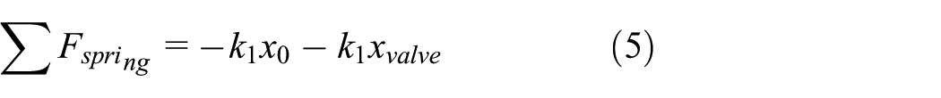
where x0 represents the constant pre-compression of valve spring, k1 is the spring rate.
The axial flow force acting on the spool induced by fluid momentum can be obtained by the momentum theory and expressed as

where
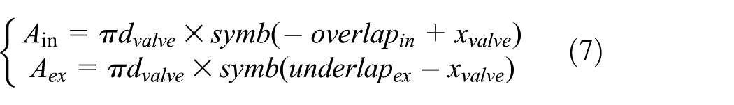
where parameter overlapin is the distance of valve spool to open the inlet port of valve from zero displacement, underlapex is the width of exhaust port corresponding to xvalve = 0, as shown in Figure 1. Symbol function symb(x) means

Flow rate of the inlet port and exhaust port is


where Cd is discharge coefficient and ρ is the density of fluid. Suppose the radial clearance between valve spool and valve sleeve is zero. The pressure of output chamber, feedback chamber, and clutch piston chamber can be modeled by the pressure-rise equation based on the conservation of flow mass in the chamber and signified as

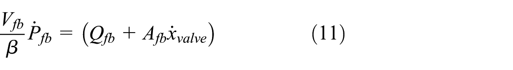

where β is the bulk modulus, Vout and Vfb are volume of output and feedback chamber. Qfb and Qc are flow rate into feedback chamber and flow rate into piston chamber, which can be denoted as
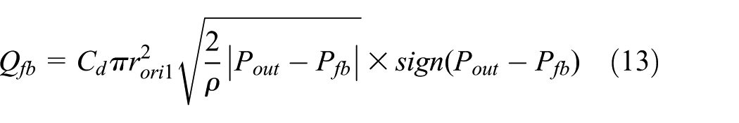
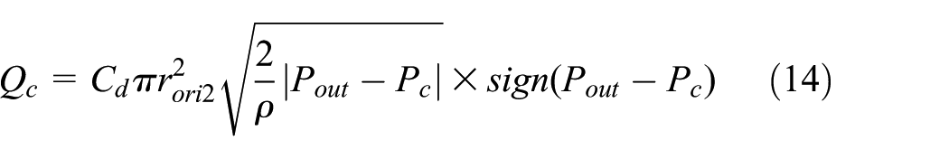
where rori1 and rori2 denote the radius of orifice1 and orifice2 shown in Figure 1. The pressure of piston chamber can be expressed by


where Ac is area of piston, Vc is volume of piston chamber, and xc is position of the piston. The piston motion can be described as

where mpiston is the mass of piston, Fpre is the preload of piston spring, cp is the damping coefficient of piston, and kp is the spring rate of piston.
To recapitulate, the governing equations of the system can be summarized as

where
Stability analysis
To study the stability of the nonlinear non-smooth hydraulic system, bifurcation analyses are carried out using numerical bifurcation method. The bifurcation diagram was computed by incrementally increasing the orifice diameter dori1 in step size of 0.1 mm. The simulation is performed in the software MATLAB.
Numerical simulations are performed to demonstrate the performance of system with parameters in the stable region and unstable region of the parameter space.
Bifurcation analysis
Numerical bifurcation analysis is utilized using ordinary differential equation (ODE) solver with adjustable error tolerance. The system parameters used in the simulations are listed in Table 1. By varying parameter dori1, a one-parameter bifurcation diagram is presented on Poincare section, as shown in Figure 5. Based on the selected Poincare plane vvalve = 0, the dots represent the displacement of valve spool and correspond to zero velocity, which represents the equilibrium point when the valve is stable, maximal and minimum displacement of valve spool during oscillation when the valve is unstable against variable orifice diameter dori1. The figure shows the effect of varying dori1 for the condition of Psol = 0.4 MPa, K = 6 N/mm. Increasing the orifice diameter from 3 mm, the equilibrium is stable until dori1 = 3.44 mm, at which point a Hopf bifurcation occurs, the difference between the maximum and minimum valve spool displacement gives the amplitude of the oscillations corresponding to different orifice diameter, which grows further in amplitude as the diameter is further increased until dori1 = 7.76 mm, at which point the valve starts to graze with the valve seat and a grazing bifurcation occurs (Figure 2).
Nominal system parameters used in simulation.


Bifurcation diagram for variable orifice diameter.
The calculated two-dimensional stability boundary for orifice diameter d and Psol is shown in Figure 3. In parameter region below the curve, the hydraulic system is stable at the equilibrium point, while in the region above the surface, the system is unstable. The system is stable with a 6-mm nominal diameter orifice under pilot-operating pressure less than 0.21 MPa. For increasing operating pressure, the system needs a smaller orifice diameter to keep it stable under increasing operating pressure until 0.39 MPa, the system needs orifice with diameter less than 3.4 mm to keep it stable. While for operating pressure beyond this value, the maximal orifice diameter value to keep the system stable increases with increasing operating pressure. The system can keep stable with 6-mm orifice under pilot-operating pressure above 0.56 MPa.

Stability boundary for orifice diameter and pilot pressure.
Numerical simulation
To examine the calculated stability boundary and study dynamic responses of the system, numerical simulation with different parameters is performed in software MATLAB using solver ode45, which implements a Runge–Kutta method with a variable time step for efficient computation. The displacement of valve spool in time domain and phase plane plot is shown in Figure 4, for dori1 =3.44 mm, k = 6 N/mm, Psol = 0.4 MPa, the system is stable after transient, the spiral in the phase plane (xvalve, vvalve) converges to the equilibrium point (xe, 0), as shown in Figure 4(a), the trajectory corresponds to damped oscillations of xvalve with time, as shown in Figure 4(b). When dori1 changes to 3.45 mm, the system exhibits as sustained oscillation after the transient, as shown in Figure 4(c). In the phase space, this oscillation corresponds to a closed curve which is a limit cycle, as shown in Figure 4(d).
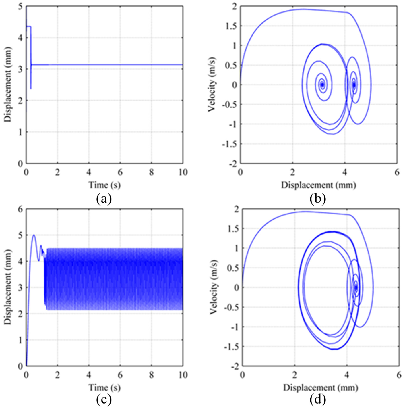
Displacement and phase portrait for different orifice diameters. (a) Time history of spool displacement, doril = 3.44 mm, (b) phase plane portrait, doril = 3.44 mm, (c) time history of spool displacement, doril = 3.45 mm, (d) phase plane portrait, doril = 3.45 mm.
Phase space plot corresponding to particular parameters is shown in Figure 5 by solving the set of equations with ODE solver to study how phase trajectory crosses with a given Poincare section changes when varying a parameter. Choose plane vvalve = 0 in the phase space as a Poincare section. For dori1 = 3.44 mm, k = 6 N/mm, and Psol = 0.4 MPa, the trajectory intersects with Poincare section at the converge point (xvalveE, 0, poutE) after sufficient transient time, as shown in Figure 5(a), while for dori1 = 3.45 mm, the trajectory intersect with Poincare section at two points representing the upper and lower position of oscillation, as shown in Figure 5(b). The output pressure of valve oscillates rapidly along with the displacement of valve spool.

Phase space portrait for different orifice diameter. (a) doril =3.44 mm and (b) doril = 3.45 mm.
Discussion
Structural and operating parameters will affect the dynamic performance of the hydraulic system greatly. Proper design of structural parameters is essential to ensure the stability of the hydraulic system during the whole operating process. Effects of system parameters on stability boundary of the system under variable operating pressure are analyzed in this section.
Effect of valve spring rate
Spring rate of the valve can affect not only the valve opening pressure but also the response speed of valve spool. Stability borders with respect to different spring rate under variable pilot pressure are calculated.
The corresponding stability boundary is shown in Figure 6. With increased spring rate, the pilot-operating pressure corresponding to the minimum value of orifice diameter on stability boundary increases and the minimum orifice diameter value on the boundary increases. A greater spring rate can improve the anti-disturbance capacity and increase the stable region of the system in the lower pressure region while under higher operating pressure, the stable region corresponding to smaller spring rate becomes larger than the region respect to greater spring rate.

Stability boundary for different spring rate.
Effect of pre-compression of valve spring
Pre-compression of the valve spring is a parameter which affects the opening pressure and the static opening of the valve. Stability boundary corresponding to different spring pre-compression x0 is calculated and shown in Figure 7.
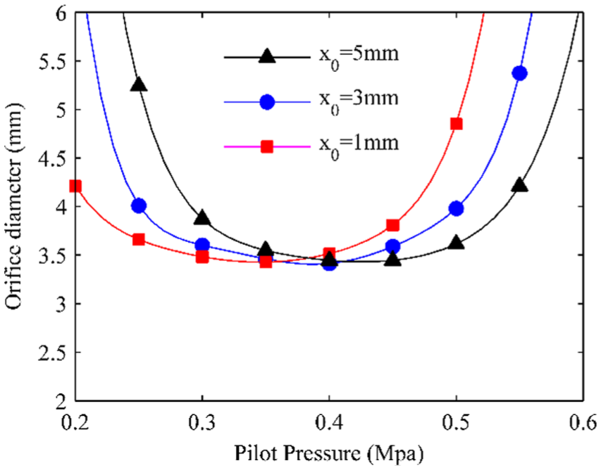
Stability border for different spring pre-compression.
For increased pre-compression of valve spring x0, the critical pilot-operating pressure corresponding to the minimum value of orifice diameter on the stability boundary curve increases, while the minimum diameter value of orifice on the curve respect to different spring pre-compression remains the same.
Effect of valve overlap
Overlap of a valve is a parameter which affects the respond time greatly. To study how it affects the stability border of a valve, the stability boundaries respect to different overlap value L1 are calculated and shown in Figure 8. As shown in the figure, an increasing overlap can enlarge the stable region of the spool valve in parameter space and enable the system to remain stable with a larger orifice diameter.

Stability boundary for different valve underlap.
Conclusion
In this article, bifurcation analysis is performed using a verified nonlinear dynamic model for the hydraulic system composed of a pilot-operated spool valve and a piston. The effects of operating condition and various design parameters on the stability of the system are discussed. The simulation results suggest that bifurcation can be created when the orifice diameter of valve is increased above the critical value and a self-excited vibration will occur in the electrohydraulic system. An increasing spring rate of valve can increase the minimum orifice diameter on the stability boundary curve and increase the critical pilot-operating pressure value corresponding to the minimum value of orifice diameter. An increasing pre-compression of valve spring can increase the critical pilot-operating pressure corresponding to the minimum value of orifice diameter on the stability boundary curve but have little effect on the minimum value of stability boundary curve. An increasing overlap can enlarge the stable region of the spool valve in parameter space and keep the system stable with a larger orifice diameter. This study provides a practical method to analysis the stability of the system, upon which an optimal design of the hydraulic system can be initiated. The model can be used to predict trends of the hydraulic system stability under various system parameters that are difficult to create experimentally and give instructions to the hydraulic system designers. Further study will include the effect of valve spool geometries on the stability of the system.
Footnotes
Handling Editor: Anand Thite
Declaration of conflicting interests
The author(s) declared no potential conflicts of interest with respect to the research, authorship, and/or publication of this article.
Funding
The author(s) disclosed receipt of the following financial support for the research, authorship, and/or publication of this article: This research was supported by the National Natural Science Foundation of China (NSFC; grant number 51475041).