
Abstract
Articulated wheel loaders that travel on unstructured roads experience severe vibration and poor stability. Introducing suspended axles on wheel loaders, which are traditionally constructed without wheel suspension, is desirable for ride comfort. This study mainly focuses on the parameter optimization of the hydropneumatic suspension to obtain the minimum root mean square of vertical accelerations under different driving conditions, thereby improving the ride comfort of the wheel loader. The multibody model of the wheel loader with hydropneumatic suspension was developed by RecurDyn in co-simulation with MATLAB/Simulink. The vertical acceleration root mean square at the seat position was analyzed when the wheel loader was traveling on class C, D, and E roads with different travel speeds. The surrogate model of the vertical acceleration root mean square with respect to the suspension parameters was established based on kriging method. The established surrogate model was then optimized using particle swarm optimization algorithm. The optimization results of the hydropneumatic suspension parameters of the wheel loader under different road excitations and driving speeds were obtained. Simulation and optimization results show that a well-designed hydropneumatic suspension system can significantly improve wheel loader performance in reducing the vertical acceleration at the seat position compared to a suspension system without optimization.
Keywords
Introduction
Wheel loaders are engineering vehicles used for various tasks that require both hauling and excavating capacity. Unlike transportation vehicles, wheel loaders are built without any axle suspension, and dynamic loads from the ground on the cab are damped by their large diameter and soft tires, suspension seat, and elastic operator cabin mounts.1,2 However, numerous field measurements have shown that the whole-body vibration (WBV) exposure of off-road vehicles exceeds the health caution guidance zone (HCGZ) defined by ISO-2631-1 3 and the exposure limit of the EN14253, 4 and the operators of the wheel loaders are exposed to remarkably higher magnitudes of WBV compared with other off-road vehicles.5–7 Furthermore, the demand for operations that need relatively higher speeds continuously increases, which yields even higher WBV magnitudes. Thus, reducing the vibration level to meet the HCGZ is difficult if the wheel loaders rely solely on the tires, the seat, and the cab suspension. Designing a vehicle with fully suspended wheel axles is the most efficient way to reduce vibrations. 8
Rehnberg and Drugge 9 established a model of a wheel loader with axle suspensions and investigated the effect of adding axle suspension on ride performance. The results showed that axle suspensions can reduce the longitudinal and vertical accelerations by 50%. Pazooki et al. 10 presented a torsio-elastic linkage suspension on an articulated wheel skidder and investigated its ride dynamic characteristics through field tests and simulations. After adding suspensions, the frequency-weighted root mean square (RMS) accelerations along the x-, y-, and z-axis reduced by 35%, 43%, and 57%, respectively. Cao et al.11,12 explored the concepts of interconnected hydropneumatic suspension for the improvement of the roll-and-pitch dynamic performance of heavy road vehicles without affecting the vehicle vertical ride. The simulation studies suggest that the interconnected hydropneumatic suspension could provide considerable benefit in realizing enhanced riding and handling performance. Hydropneumatic suspension can achieve the functions of anti-roll,anti-pitch, and balance shaft load through different interconnection struts. However, the use of a hydropneumatic suspension to achieve good damping requires a comprehensive consideration of various factors including road excitation, travel speed, suspension stiffness, and suspension damping. It is a very meaningful job to set the corresponding stiffness and damping of the hydropneumatic suspension under specific road excitation and driving speed.
An articulated wheel loader with interconnected hydropneumatic suspension is developed in this study to achieve improved ride performance. The structure of this article is as follows. Section “Vehicle modeling” describes the articulated wheel loader with interconnected hydropneumatic suspension and the developed multibody simulation model. Section “Analytical models of the hydropneumatic suspension systems” presents the generalized forces for the interconnected hydropneumatic suspension. Section “Optimization of hydropneumatic suspension based on kriging model and particle swarm algorithm” describes the optimization method of the hydropneumatic suspension based on Kriging and particle swarm optimization (PSO) and gives the optimization results. Finally, conclusions are presented in section “Conclusion.”
Vehicle modeling
This study proposes an articulated wheel loader with hydropneumatic suspensions for the improvement of ride comfort, as shown in Figure 1. The hydropneumatic suspensions are installed on the front and rear axles. The axles are subjected to large load when the loader is in operation; thus, non-independent suspension structures are adopted to ensure sufficient strength.
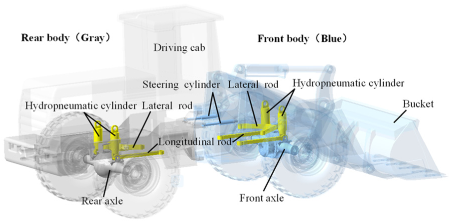
Structure of the wheel loader with hydropneumatic suspension.
The articulated wheel loader is modeled using the multibody dynamics software RecurDyn (FunctionBay, Inc., Korea). RecurDyn is a modeling and simulation commercial software package for building and simulating a multibody system. The front axle is attached to the front frame using the hydropneumatic cylinder, where one spherical joint connects the front axle to the cylinder rod, and the other connects the cylinder tube to the front frame. The piston rod and the cylinder tube are constrained by a translational joint. Furthermore, longitudinal and lateral rods, which are connected to the front frame and the front axle through spherical joints, are used to carry longitudinal and lateral forces in the axle suspension. The rear axle and the rear frame are connected in the same manner as the front ones. The front and rear frames are constrained by a revolute joint; the relative yaw angle between these two parts is changed by two steering cylinders.
The Fiala tire model thoroughly describes the relationship among the lateral, vertical, and longitudinal forces, the slip angle, and the slip ratio of the tires; this model has been verified by experiments. 13 Table 1 shows the parameters for the Fiala tire model. 14 The properties of the front and rear tires are assumed equal. Table 2 shows the dimensions and specifications of the developed wheel loader model. The moment of inertia and the center of gravity are all relative to the global coordinate system o-xyz, which is located at the articulated center of the front and rear bodies, and x direction coincides with the forward direction of the vehicle, z direction is opposite to the direction of gravity, and y direction is determined by the right-hand rule.
Fiala tire model properties.

Parameters of the wheel loader model.

Analytical models of the hydropneumatic suspension systems
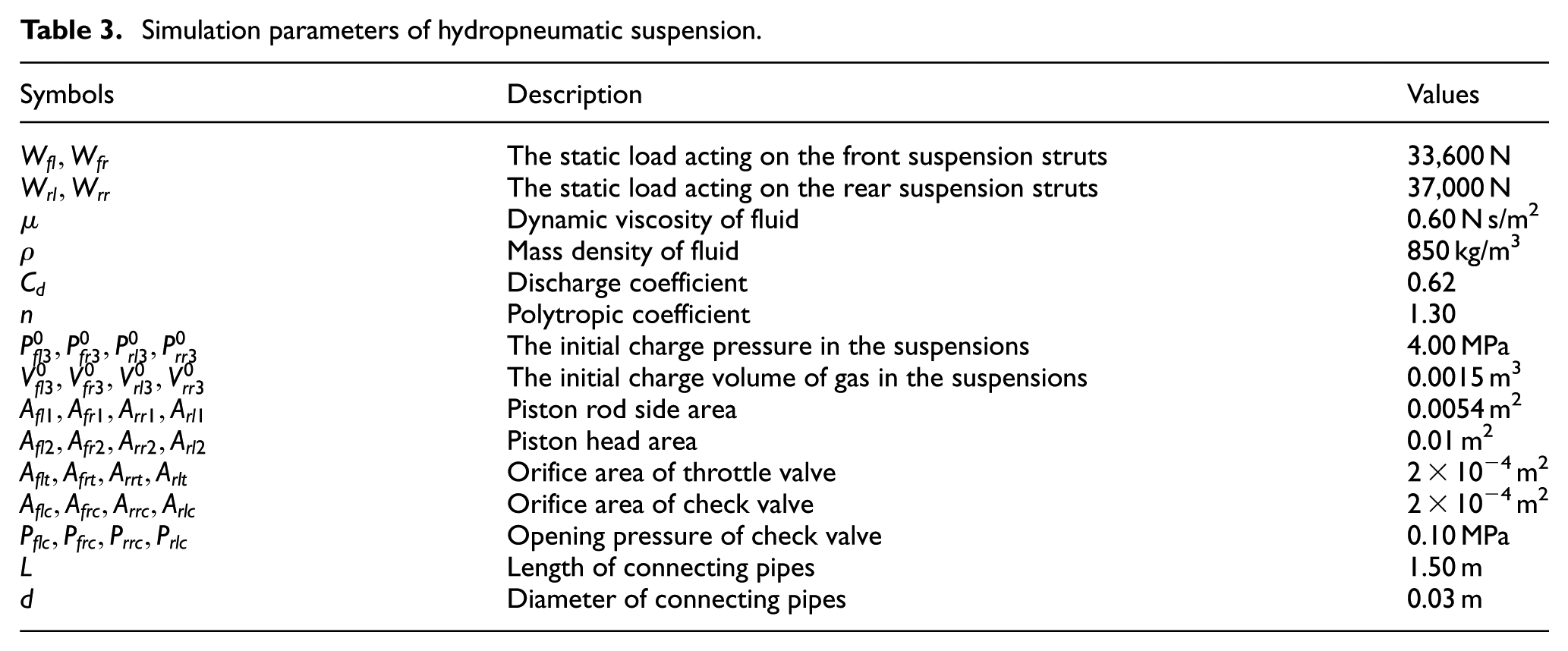
Previous studies have shown that an interconnected hydropneumatic suspension can enhance riding and handling performance. The wheel loader in this study adopts a roll-plane interconnected hydropneumatic suspension (Figure 2), the front-left and the front-right chambers of the struts are interlinked in a cross formation; symmetrically, the rear-left and the rear-right chambers of the struts are also interlinked in a cross formation. Figure 2(b) shows a sample calculation of the interconnected suspension of the suspension forces due to connection symmetry, where the interconnection of the front-left and front-right chambers of the struts is selected to derive the suspension force. The meanings of the symbols in the figure are shown in Table 3. To facilitate the description, the “front-left,”“front-right,”“rear-left,” and “rear-right” are abbreviated as “fl,”“fr,”“rl,” and “rr” in the subscript of the symbols, respectively. For example, Ffl represents the suspension force of the front-left strut.
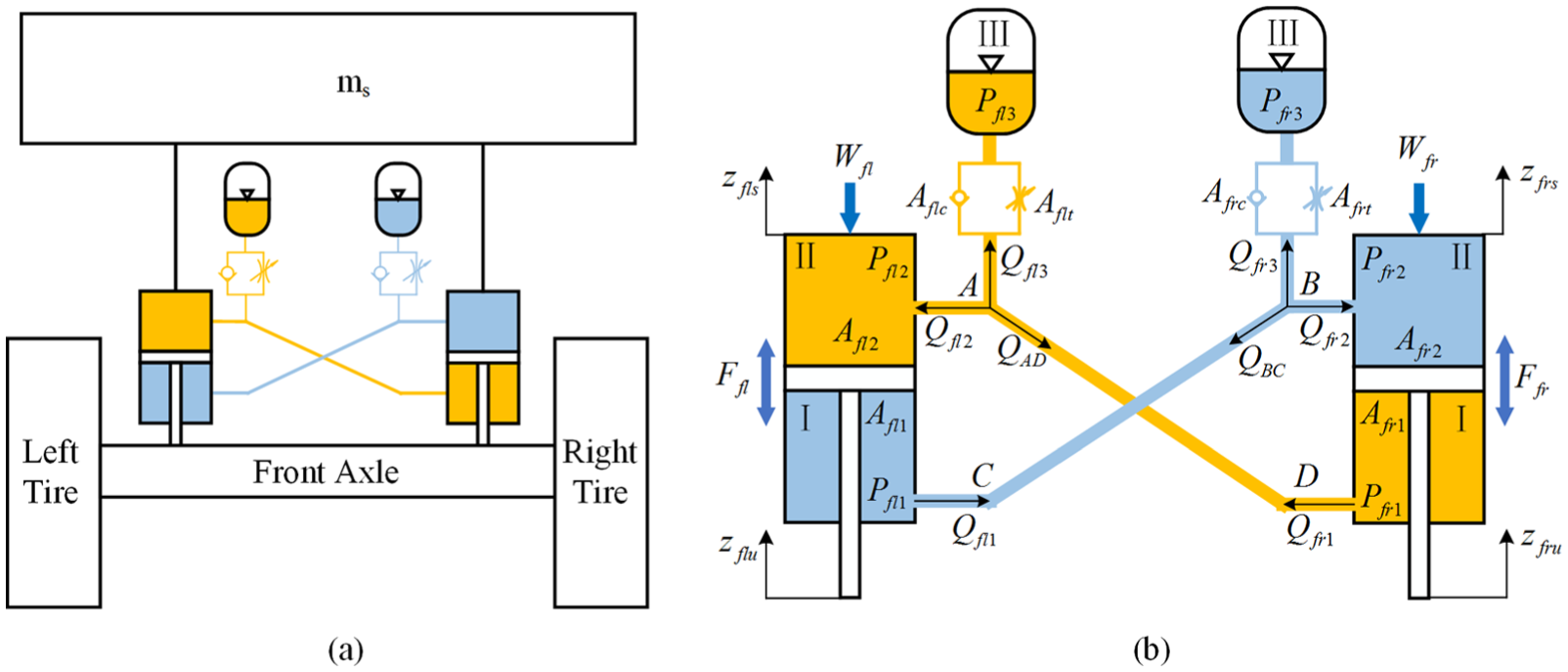
Schematic representations of the interconnected hydropneumatic suspension: (a) Layout of hydropneumatic suspension; and (b) Schematic representations of the interconnected hydropneumatic suspension.
Simulation parameters of hydropneumatic suspension.
Many previous studies have given mathematical expressions for interconnected hydropneumatic suspensions,15,16 the fluid pressure in chambers I and II of struts FL and FR can be expressed as

The fluid pressure in chambers I and II of struts RL and RR can be expressed as

Suspension parameters
The suspension characteristics are based on a set of physical parameters such as static load, charge pressure and volume, orifice area, length, and diameter of interconnection pipe. These parameters are presented in Table 3. Each of the parameters is selected based on identical load carrying capacity, static deflection, and static stiffness at design ride height. This ensures that the sprung mass natural frequency within the preferred range for ride quality.
Dynamic force of the interconnected suspension
The forces of hydropneumatic suspension are the forces acting on the pistons, which can be calculated as follows

The multibody model of the wheel loader with hydropneumatic suspension is developed by RecurDyn in co-simulation with MATLAB/Simulink, as shown in Figure 3. The virtual prototype model established in RecurDyn exports velocities and displacements of the cylinder tubes and piston rods of the hydropneumatic cylinders to Simulink. The suspension forces calculated in Simulink are sent back to RecurDyn.
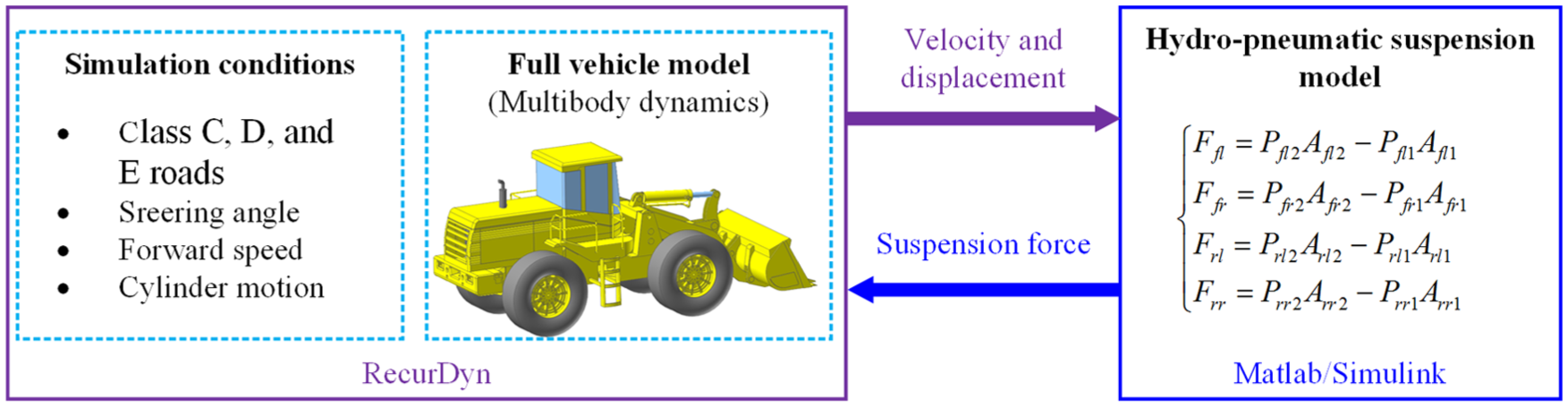
Co-simulation interaction.
Optimization of hydropneumatic suspension based on kriging model and particle swarm algorithm
Establishing the response model of the acceleration root mean square (RMS) with respect to stiffness and damping is complicated due to the nonlinear relationship between the vertical acceleration RMS and the suspension parameters. In this study, kriging method was used to establish the surrogate model between the vertical acceleration RMS and suspension parameters. Then, PSO algorithm was adopted to optimize the hydropneumatic suspension parameters to reduce the vertical acceleration and improve ride comfort. The process for establishing kriging surrogate model and optimizing the suspension parameters is as follows:
Sample points for the hydropneumatic suspension parameters were selected.
The established dynamic model was used to analyze the loader vibration characteristics corresponding to each sample point under different road excitations and driving speeds.
The vehicle acceleration RMS corresponding to each sample point under different conditions could be obtained.
A kriging surrogate model was established for the vertical acceleration RMS with respect to the suspension parameters.
PSO algorithm was used to optimize hydropneumatic suspension parameters.
Establishment of the Kriging surrogate model
Selection of sample points
The Latin hypercube method is chosen to select sample points when establishing the Kriging model. This method can evenly distribute the sample points to the entire design space. The sampling range of design variables is shown in Table 4. The obtained 30 sample points are shown in Table 5.
Sampling range of design variables.

Sample points obtained by the Latin hypercube method.

Vertical acceleration response of each sample point under different road excitations and driving speeds
Road excitations
The International Organization for Standardization (ISO) has proposed a series of standards of road roughness classification using power spectral density values. Wheel loaders are off-road vehicles that travel on complex and poor roads. Three types of roads, namely, class C, D, and E, were selected as input incentives in this study.
Driving speeds
Eight different speeds were selected for class C and D roads, that is, 5, 10, 15, 20, 25, 30, 35, and 40 km/h. Only six driving speeds of 5, 10, 15, 20, 25, and 30 km/h were selected on class E road surface due to poor road conditions.
Analysis of vertical acceleration responses under different conditions
The standard ISO 2631-1:1997 establishes a method for assessing the effects of periodic, random, and transient whole-body vibration on the human body. The basic evaluation method, which is the calculation of the weighted acceleration RMS, was adopted in this study. The weighted RMS accelerations were calculated as follows

where
The vertical acceleration response corresponding to each sample point was analyzed based on the established dynamic model. Sample point 1 was taken as an example when the wheel loader was driving at a speed of 5 km/h on a class C road surface. Figure 4 shows the vertical acceleration response at the seat position. Through the statistical analysis of the acceleration, the RMS value was 198.51 mm/s2. Similarly, the vertical acceleration RMS values of the other sample points under different conditions could also be obtained.

Vertical acceleration response at the seat position.
Establishing the kriging-based surrogate model of the RMS acceleration with respect to the suspension parameters
Kriging is a spatial interpolation method based on the geostatistical variogram model. It uses the raw data of the regionalization variables and the structural characteristics of the variogram to optimize the values of the unsampling regional variables. The Kriging model has global characteristics rather than local characteristics and is used to predict unknown points based on known points. The construction of kriging model consists of two parts: regression model and Gaussian stochastic process, is formulated as

where Pk is the response (output) of the kriging model, which depends on a vector of input a. R is a regression function which is built based on the simulated data. Z is a zero mean Gaussian process which is constructed for the residuals.
The development of the Kriging method has formed a complete theoretical system and has produced some practical and effective programs and software. More information on Kriging’s mathematical model can be found in books such as the ones by Forrester et al. 17 and Santner et al. 18 The Kriging module is specially provided in MATLAB, and its main program is as follows

where S represents the obtained 30 sample points of the hydropneumatic suspension and Y denotes the acceleration RMS. The constant regression function and Gaussian correlation equation were selected; theta was the correlation function parameter and was set to [10,10,10] in this study. lob and upb indicate the upper and lower limits of the output, respectively.
The procedure for predicting the response results based on the established kriging model is as follows

where [a1, a2,a3] is the coordinate value of the point to be predicted, a1 represents the initial charge pressure, a2 denotes the initial charge volume, and a3 indicates the damping hole diameter. dmodel refers to the kriging-based surrogate model of the suspension parameters with respect to the acceleration RMS.
Parameter optimization analysis of hydropneumatic suspension based on PSO algorithm
Objective function
The purpose of the optimization of the hydropneumatic suspension system is to improve the ride comfort under the premise of ensuring the stable running of the wheel loader. The ride comfort of the wheel loader depends mainly on the vertical acceleration at the seat position. In this work, the objective function was defined as the acceleration RMS at the seat position, as shown as follows

where X represents design variables, aw denotes the RMS acceleration at the seat position, and function f is the kriging-based surrogate model.
Design variables
The parameters affecting the characteristics of the hydropneumatic suspension mainly include the initial charge pressure, initial charge volume, and damping hole diameter. The design variables are defined as

where P is the initial gas pressure, V is the initial gas volume, and D is the damping hole diameter.
Constraints
Suspension deflection constraint
The vehicle body and limit block would collide if the suspension deflection exceeds the range, thereby deteriorating the ride comfort of the vehicle. The suspension deflection is restricted as follows

where
Tire dynamic load constraint
Keeping the tires in contact with the ground at all times is necessary; otherwise, the vehicle will be in an unstable state. When the ratio of the tire dynamic load to the tire static load is less than 1/3, the probability of the tire lifting off the ground will be reduced to 0.003. The tire dynamic load is restricted as follows

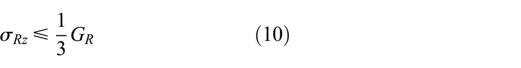
where
Optimization algorithm
There are many common optimization methods, such as genetic algorithm, ant colony algorithm, bee colony algorithm, and PSO algorithm. The PSO algorithm is used to optimize the parameters of hydropneumatic suspension in this article. The PSO algorithm is based on a metaphor of social interaction and it has been extensively applied in previous studies.20,21 It starts with a swarm of particles spread in the search space randomly. Each particle represents a potential solution to the optimization problem. The algorithm searches the space by adjusting the trajectories of the individual particles based on their own and their neighbor’s previous best to find the optimal solution. The hybrid bare-bones PSO can be used to deal with the dynamic load constraint problem of loader tires. This strategy can provide a good direction to optimal regions and effectively solve the dynamic economic dispatch with value-point effects.22,23
Results
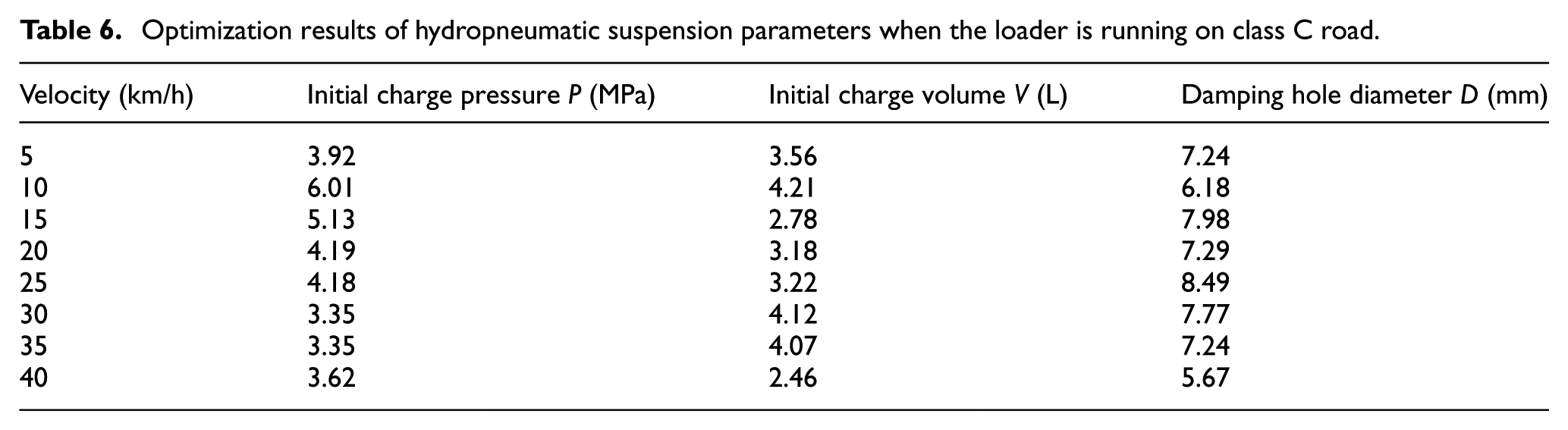
The PSO algorithm was used with the parallel toolbox of MATLAB to optimize the parameters of hydropneumatic suspension for the abovementioned wheel loader. The number of particles in each swarm was 50, and the loop times were 300. The objective function dimension was 3. The value range of inertia weight was 0.4–0.9, and the particle acceleration coefficients were 2. Tables 6–8 show the optimization results of the parameters of the hydropneumatic suspension when the wheel loader is running at different speeds on class C, D, and E roads. Figure 5 shows the vertical acceleration at the seat position when the wheel loader is driving at different speeds on a class C road before and after optimization. Form the figure, the optimized suspension system has an improved damping effect.
Optimization results of hydropneumatic suspension parameters when the loader is running on class C road.
Optimization results of hydropneumatic suspension parameters when the loader is running on class D road.

Optimization results of hydropneumatic suspension parameters when the loader is running on class E road.


Comparison of vertical acceleration at the seat position before and after optimization of suspension parameters.
The vertical acceleration in Figure 5 was statistically analyzed to obtain the RMS of acceleration. Figure 6(a) shows the comparison of the acceleration RMS of the wheel loader with different speeds on class C road before and after optimizing the suspension parameters. Similarly, the acceleration RMS of the wheel loader traveling on class D and E roads could also be obtained, as shown in Figures 6(b) and (c). From the figures, the acceleration RMS is reduced after the optimization of the suspension parameters under all research conditions. Particularly, the optimization effect is significant when the speed is between 20 and 30 km/h and the reduction of acceleration RMS reaches more than 40%. However, the optimized damping effect has no obvious advantage when the driving speed of the wheel loader reaches 40 km/h. The loader can only achieve speeds above 40 km/h on good road surfaces, such as class A and B roads.
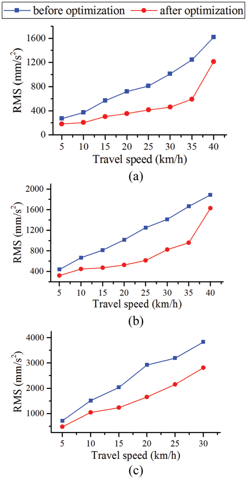
Comparison of acceleration RMS before and after optimization: (a) class C road, (b) class D road, and (e) class E road.
Conclusion
Traditional wheel loaders are constructed without any axle suspension and thus experience severe vibration. This study proposed an articulated wheel loader with roll-plane-interconnected hydropneumatic suspensions for the improvement of ride comfort. A multibody model of the wheel loader with interconnected hydropneumatic suspension of wheel axles was developed using the multibody dynamics software RecurDyn. The hydropneumatic suspension was modeled using MATLAB/Simulink, and the RecurDyn full vehicle model was provided with a suspension force via co-simulation.
Thirty parameter sample points for the hydropneumatic suspension were selected using the Latin hypercube method. The vertical acceleration responses corresponding to all 30 sample points were analyzed when the wheel loader was driving at different speeds on class C, D, and E roads. On the basis of these response data, the surrogate model of the vertical acceleration RMS with respect to the suspension parameters was established using the kriging method. The optimization model was established with the minimum vertical acceleration RMS as the objective function, the suspension parameters as the optimization variables, and the stability of the loader as the constraint condition. The PSO algorithm was used to optimize the model, and the parameters of the hydropneumatic suspension that could minimize the vertical acceleration under different conditions of the loader were obtained. This study presents a method for optimizing the parameters of hydropneumatic suspensions installed on the wheel loader, which provides the basis for the active adjustment of the parameters of hydropneumatic suspension for future works.
Footnotes
Handling Editor: Seung-Bok Choi
Declaration of conflicting interests
The author(s) declared no potential conflicts of interest with respect to the research, authorship, and/or publication of this article.
Funding
The author(s) disclosed receipt of the following financial support for the research, authorship, and/or publication of this article: This study was supported by the National Natural Science Foundation of China (grant no. 51505177), Science and Technology Development Program of Jilin Province (grant no. 20160520073JH), and Postdoctoral Science Foundation of China (grant no. 163808).